EP0406775A2 - Rectifieuse - Google Patents
Rectifieuse Download PDFInfo
- Publication number
- EP0406775A2 EP0406775A2 EP90112612A EP90112612A EP0406775A2 EP 0406775 A2 EP0406775 A2 EP 0406775A2 EP 90112612 A EP90112612 A EP 90112612A EP 90112612 A EP90112612 A EP 90112612A EP 0406775 A2 EP0406775 A2 EP 0406775A2
- Authority
- EP
- European Patent Office
- Prior art keywords
- axis
- wheel
- worktable
- grinding machine
- saddle
- Prior art date
- Legal status (The legal status is an assumption and is not a legal conclusion. Google has not performed a legal analysis and makes no representation as to the accuracy of the status listed.)
- Withdrawn
Links
- 230000002441 reversible effect Effects 0.000 description 3
- 238000000034 method Methods 0.000 description 2
- 238000010586 diagram Methods 0.000 description 1
- 239000012535 impurity Substances 0.000 description 1
- 238000003754 machining Methods 0.000 description 1
- 238000009877 rendering Methods 0.000 description 1
- 239000007787 solid Substances 0.000 description 1
Images

Classifications
-
- B—PERFORMING OPERATIONS; TRANSPORTING
- B24—GRINDING; POLISHING
- B24B—MACHINES, DEVICES, OR PROCESSES FOR GRINDING OR POLISHING; DRESSING OR CONDITIONING OF ABRADING SURFACES; FEEDING OF GRINDING, POLISHING, OR LAPPING AGENTS
- B24B27/00—Other grinding machines or devices
- B24B27/0084—Other grinding machines or devices the grinding wheel support being angularly adjustable
-
- B—PERFORMING OPERATIONS; TRANSPORTING
- B23—MACHINE TOOLS; METAL-WORKING NOT OTHERWISE PROVIDED FOR
- B23Q—DETAILS, COMPONENTS, OR ACCESSORIES FOR MACHINE TOOLS, e.g. ARRANGEMENTS FOR COPYING OR CONTROLLING; MACHINE TOOLS IN GENERAL CHARACTERISED BY THE CONSTRUCTION OF PARTICULAR DETAILS OR COMPONENTS; COMBINATIONS OR ASSOCIATIONS OF METAL-WORKING MACHINES, NOT DIRECTED TO A PARTICULAR RESULT
- B23Q1/00—Members which are comprised in the general build-up of a form of machine, particularly relatively large fixed members
- B23Q1/25—Movable or adjustable work or tool supports
- B23Q1/44—Movable or adjustable work or tool supports using particular mechanisms
- B23Q1/48—Movable or adjustable work or tool supports using particular mechanisms with sliding pairs and rotating pairs
-
- B—PERFORMING OPERATIONS; TRANSPORTING
- B24—GRINDING; POLISHING
- B24B—MACHINES, DEVICES, OR PROCESSES FOR GRINDING OR POLISHING; DRESSING OR CONDITIONING OF ABRADING SURFACES; FEEDING OF GRINDING, POLISHING, OR LAPPING AGENTS
- B24B41/00—Component parts such as frames, beds, carriages, headstocks
- B24B41/02—Frames; Beds; Carriages
Definitions
- the present invention relates to a grinding machine.
- Solids of rotation particularly shafts of any external shape, are known to be ground on machines comprising a worktable, usually horizontal, having a headstock and tailstock for supporting and rotating the work about its longitudinal axis.
- the worktable is usually designed to travel along a longitudinal axis, for which purpose it is mounted on slideways arranged parallel to the longitudinal axis of the work and on which it travels past a grinding wheel usually supported on a saddle moving to and from the worktable along a transverse axis usually perpendicular to the traveling direction of the worktable.
- cylindrical surfaces are nearly always ground by setting the outer surface of the wheel parallel to the cylindrical surface of the work, and by moving the worktable along the longitudinal axis and the saddle along the transverse axis, which extends perpendicular to the longitudinal axis when using cylindrical wheels.
- the worktable On non-numerical-control machines, the worktable usually consists of a platform mounted on said longitudinal slideways and designed to turn in relation to the same about a normally vertical axis, at any rate perpendicular to the plane defined by the longitudinal and transverse traveling directions of the worktable and saddle respectively.
- conical surfaces are usually ground by rotating the worktable so that the generating line of the conical surface facing the wheel is parallel to the outer surface of the wheel, and by moving the worktable so positioned along the longitudinal slideways, thus enabling the wheel to explore said generating line and grind the conical surface in the same way as a cylindrical surface.
- the wheel was usually mounted on the saddle via the interposition of a platform turning about a normally vertical axis, at any rate perpendicular to the plane defined by the traveling direction of the worktable and saddle.
- conical surfaces were usually ground by rotating the platform in such a manner as to set the outer surface of the wheel parallel to the generating line of the conical work surface facing the wheel, and by simultaneously moving the work and wheel, via interpolation of the respective longitudinal and transverse traveling directions of the worktable and saddle, so as to enable the wheel to explore the generating line of the work facing it.
- a grinding machine comprising a worktable traveling along a first longitudinal axis parallel to the axis of the workpiece; at least one grinding wheel; and a wheel supporting saddle moving to and from said worktable along a second axis usually arranged crosswise in relation to said first axis; characterised by the fact that it also comprises a wheel table supporting said wheel saddle and traveling along a third longitudinal axis adjustable in relation to said first longitudinal axis and about a fourth axis perpendicular to said second and third axes.
- cylindrical portions may be ground by maintaining the wheel table stationary, parallel to the worktable, and moving the worktable along said first longitudinal axis; whereas conical portions may be ground by positioning said third axis, and consequently said wheel table, parallel to the generating line of the cone facing them, and by moving the wheel table along said third axis while maintaining the worktable stationary.
- said second axis on the above machine is preferably adjustable about a fifth axis parallel to said fourth axis.
- Number 1 in Fig.1 indicates a grinding machine comprising a bed 2, a front portion 3 of which supports fixed slideways 4 for a worktable 5 connected to a reversible motor 6 so as to travel along slideways 4 in the direction of a first horizontal longitudinal axis 7.
- the terms “longitudinal” and “transverse” refer to the workpiece.
- the term “longitudinal axis” indicates an axis or, generally speaking, a direction generally parallel to the longitudinal axis of the workpiece; whereas the term “transverse axis” indicates an axis or, generally speaking, a direction generally transversal to the longitudinal axis of the workpiece.
- Worktable 5 is fitted with top slideways 8 extending in the direction of axis 7 and supporting in sliding manner a powered headstock 9 and a tailstock 10 for supporting and rotating workpiece A about its longitudinal axis parallel to axis 7.
- a wheel table 12 On a portion 11 of bed 2 extending rearwards from an intermediate portion of front portion 3, there is mounted a wheel table 12 connected to a reversible motor 13 so as to travel along slideways 14 in the direction of a second horizontal longitudinal axis 15.
- Slideways 14 are connected to portion 11 of bed 2 via the interposition of a platform 16 designed to turn, in relation to bed 2, about a vertical axis 17, for positioning axis 15 in relation to axis 7, and inclining axis 15 in relation to axis 7 at any angle usually ranging from 0° to 15°.
- Wheel table 12 supports a central plate 18 on which is mounted for rotation, about a second vertical axis 19, a guide device 20 for a wheel saddle 21 connected to a reversible motor 22 so as to travel on guide device 20 in the direction of a horizontal transverse axis 23.
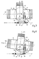
- Wheel table 12 is fitted with two stops 24, 25 (Fig.5) for generally limiting rotation of axis 23 in relation to axis 15 to 30° as of a "zero" position wherein guide device 20 contacts stop 24 and axis 23 is perfectly perpendicular to axis 15.
- Wheel saddle 21 is fitted through with a shaft 26 mounted for rotation about a horizontal axis 27 perpendicular to axis 23.
- One end of shaft 26 is fitted with a grinding wheel 28, the edge of which projects frontwards of saddle 21 in the direction of worktable 5.
- the other end of shaft 26 is connected to a drive 29 connecting shaft 26 to a motor 30 powering wheel 28 on saddle 21.
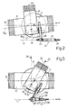
- Fig.s 2 to 4 show a cylindrical wheel 28 used for grinding a shaft 31 having a cylindrical central portion 32 and two opposed conical end portions 33, 34, and the longitudinal axis of which is illustrated for simplicity as coinciding with axis 7.
- Shaft 31 is ground in one pass commencing, for example, with conical portion 33.
- wheel table 12 is rotated about axis 17 so as to set axis 15, formerly parallel to axis 7, into position 15a, wherein axis 27 is positioned parallel to the generating line of the conical surface of conical portion 33 facing wheel 28.
- motor 6 is left idle for maintaining shaft 31 in its original position along axis 7, whereas motor 22 is operated for bringing wheel 28 into contact with portion 33, and motor 13 for moving wheel table 12 along axis 15a and so enabling wheel 28 to explore portion 33.
- wheel table 12 is then turned about axis 17 so as to return axis 15 to its original position parallel to axis 7, and, upon wheel 28 contacting portion 32, motor 13 is left idle for maintaining wheel table 12 stationary, whereas worktable 5 is moved along axis 7 via motor 6, so as to enable wheel 28 to explore cylindrical portion 32.
- any inaccuracy may be rectified at any time by truing the grinding wheel.
- the truing tool (not shown) is supported on worktable 5 and provides for rendering the working surface of wheel 28 perfectly parallel to fixed axis 7.
- this would not be possible in that truing of the wheel provides for compensating for any errors in the position of the wheel in relation to a fixed axis, but not for any errors in the annular position of an adjustable axis in relation to the wheel.
- wheel table 12 is turned about axis 17 so as to set axis 15, formerly parallel to axis 7, into position 15b wherein axis 27 is positioned parallel to the generating line of the conical surface of conical portion 34 facing wheel 28.
- motor 6 is left idle for maintaining shaft 31 stationary along axis 7, whereas motor 13 is operated for moving wheel table 12 along axis 15b and so enabling wheel 28 to explore conical portion 34.
- Fig.5 shows a conical wheel 28a used for grinding a shaft 35 having a number of cylindrical portions 36 separated by shoulders 37, and a conical end portion 38.
- saddle 21 is turned about axis 19 so as to bring guide device 20 into contact with stop 25 and set the outer surface of wheel 28a parallel to axis 7.
- Cylindrical portions 36 and conical portion 38 of shaft 35 are then ground as already described with reference to Fig.s 2 to 4.
- saddle 21 supports, in known manner, a second internal grinding wheel connected to saddle 21 by means of a supporting device designed to move between an operating and an idle position. With the support set to the operating position, both cylindrical and conical holes may be ground in the same way as described with reference to wheel 28.
Landscapes
- Engineering & Computer Science (AREA)
- Mechanical Engineering (AREA)
- Grinding Of Cylindrical And Plane Surfaces (AREA)
Applications Claiming Priority (2)
| Application Number | Priority Date | Filing Date | Title |
|---|---|---|---|
| IT8967564A IT1232139B (it) | 1989-07-07 | 1989-07-07 | Macchina rettificatrice |
| IT6756489 | 1989-07-07 |
Publications (2)
| Publication Number | Publication Date |
|---|---|
| EP0406775A2 true EP0406775A2 (fr) | 1991-01-09 |
| EP0406775A3 EP0406775A3 (en) | 1991-05-22 |
Family
ID=11303475
Family Applications (1)
| Application Number | Title | Priority Date | Filing Date |
|---|---|---|---|
| EP19900112612 Withdrawn EP0406775A3 (en) | 1989-07-07 | 1990-07-02 | Grinding machine |
Country Status (2)
| Country | Link |
|---|---|
| EP (1) | EP0406775A3 (fr) |
| IT (1) | IT1232139B (fr) |
Cited By (5)
| Publication number | Priority date | Publication date | Assignee | Title |
|---|---|---|---|---|
| EP0477732A1 (fr) * | 1990-09-28 | 1992-04-01 | Toyoda Koki Kabushiki Kaisha | Procédé et dispositif de meulage |
| WO1995004629A1 (fr) * | 1993-08-07 | 1995-02-16 | Strausak Ag Maschinenfabrik | Station universelle de meulage |
| ES2376813A1 (es) * | 2011-11-10 | 2012-03-20 | Danobat, S. Coop. | Sistema para rectificado de piezas con aristas redondeadas o biseladas. |
| CN111113197A (zh) * | 2019-12-24 | 2020-05-08 | 嘉善金嘉塑业有限公司 | 一种塑料制品加工用打磨设备 |
| CN112975584A (zh) * | 2021-03-02 | 2021-06-18 | 济源市格林园艺制品有限公司 | 一种石塑花盆的制备方法及其打磨装置 |
Families Citing this family (2)
| Publication number | Priority date | Publication date | Assignee | Title |
|---|---|---|---|---|
| CN110948228B (zh) * | 2019-11-05 | 2020-12-04 | 杨茂周 | 一种汽车传动轴管的制备装置及其制备方法 |
| CN111152078B (zh) * | 2020-01-18 | 2021-08-10 | 河北拓思机械设备有限公司 | 成型刀具研磨机 |
Citations (2)
| Publication number | Priority date | Publication date | Assignee | Title |
|---|---|---|---|---|
| GB944665A (en) * | 1960-10-05 | 1963-12-18 | Farrel Birmingham Co | Improvements in roll-grinding mechanisms |
| DE1652021A1 (de) * | 1966-12-02 | 1971-09-16 | Cincinnati Milling Machines Lt | Schleifmaschine |
-
1989
- 1989-07-07 IT IT8967564A patent/IT1232139B/it active
-
1990
- 1990-07-02 EP EP19900112612 patent/EP0406775A3/en not_active Withdrawn
Patent Citations (2)
| Publication number | Priority date | Publication date | Assignee | Title |
|---|---|---|---|---|
| GB944665A (en) * | 1960-10-05 | 1963-12-18 | Farrel Birmingham Co | Improvements in roll-grinding mechanisms |
| DE1652021A1 (de) * | 1966-12-02 | 1971-09-16 | Cincinnati Milling Machines Lt | Schleifmaschine |
Cited By (7)
| Publication number | Priority date | Publication date | Assignee | Title |
|---|---|---|---|---|
| EP0477732A1 (fr) * | 1990-09-28 | 1992-04-01 | Toyoda Koki Kabushiki Kaisha | Procédé et dispositif de meulage |
| US5228241A (en) * | 1990-09-28 | 1993-07-20 | Toyoda Koki Kabushiki Kaisha | Method and machine for grinding |
| WO1995004629A1 (fr) * | 1993-08-07 | 1995-02-16 | Strausak Ag Maschinenfabrik | Station universelle de meulage |
| ES2376813A1 (es) * | 2011-11-10 | 2012-03-20 | Danobat, S. Coop. | Sistema para rectificado de piezas con aristas redondeadas o biseladas. |
| CN111113197A (zh) * | 2019-12-24 | 2020-05-08 | 嘉善金嘉塑业有限公司 | 一种塑料制品加工用打磨设备 |
| CN112975584A (zh) * | 2021-03-02 | 2021-06-18 | 济源市格林园艺制品有限公司 | 一种石塑花盆的制备方法及其打磨装置 |
| CN112975584B (zh) * | 2021-03-02 | 2022-12-13 | 济源市格林园艺制品有限公司 | 一种石塑花盆的打磨装置 |
Also Published As
| Publication number | Publication date |
|---|---|
| IT8967564A0 (it) | 1989-07-07 |
| IT1232139B (it) | 1992-01-23 |
| EP0406775A3 (en) | 1991-05-22 |
Similar Documents
| Publication | Publication Date | Title |
|---|---|---|
| US6666748B2 (en) | Machining center and method of changing tools thereof | |
| KR20010093144A (ko) | 공작물의 황삭연마중 공정을 제어하는 방법과 연마기 | |
| JPH06510950A (ja) | 被加工部材の研削方法および装置 | |
| KR940003150B1 (ko) | 수치 제어되는 공작 기계상에서 공작물의 미스얼라인먼트를 보정하는 방법 | |
| US6685536B1 (en) | Method for grinding convex running faces and outside diameters on shaft-like workpieces in one set-up and grinding machine for carrying out the method | |
| JPH0899242A (ja) | 複合加工用の工作機械 | |
| US5766059A (en) | Method of grinding a workpiece | |
| JPH05208356A (ja) | カップ研削盤 | |
| EP0406775A2 (fr) | Rectifieuse | |
| US4494280A (en) | Method and machine tool for a circular machining of eccentric shaft portions | |
| US4443975A (en) | Dual wheel cylindrical grinding center | |
| EP0823310A1 (fr) | Machine-outil mixte | |
| US4341044A (en) | Machine for grinding gashes in end mill cutters | |
| JP3566403B2 (ja) | 主軸テーパ穴再研装置 | |
| CN110936245A (zh) | 一种盘式刹车片内外弧边缘倒角磨床 | |
| US5435360A (en) | Method for positioning a machine element having a reference point relative to a reference point provided at an abutment | |
| CN211439305U (zh) | 一种盘式刹车片内外弧边缘倒角磨床 | |
| CN113997183A (zh) | 一种多工位铣刀加工装置 | |
| JP2609988B2 (ja) | ホーニング治具および自動ホーニングシステム | |
| JP2000042878A (ja) | 円筒研削盤及びそのワーク軸と砥石軸、並びにこの円筒研削盤による平錐の加工方法 | |
| JP2001062682A (ja) | テーブル切込み式研削盤 | |
| JPH05200649A (ja) | 工具心出し装置 | |
| CN216327401U (zh) | 一种多工位铣刀加工装置 | |
| JP3834493B2 (ja) | 複合研削方法及び装置 | |
| US3813824A (en) | Duplicating grinding machine |
Legal Events
| Date | Code | Title | Description |
|---|---|---|---|
| PUAI | Public reference made under article 153(3) epc to a published international application that has entered the european phase |
Free format text: ORIGINAL CODE: 0009012 |
|
| AK | Designated contracting states |
Kind code of ref document: A2 Designated state(s): CH DE ES FR GB IT LI |
|
| PUAL | Search report despatched |
Free format text: ORIGINAL CODE: 0009013 |
|
| AK | Designated contracting states |
Kind code of ref document: A3 Designated state(s): CH DE ES FR GB IT LI |
|
| 17P | Request for examination filed |
Effective date: 19911107 |
|
| 17Q | First examination report despatched |
Effective date: 19921222 |
|
| STAA | Information on the status of an ep patent application or granted ep patent |
Free format text: STATUS: THE APPLICATION IS DEEMED TO BE WITHDRAWN |
|
| 18D | Application deemed to be withdrawn |
Effective date: 19931125 |