EP0406543A2 - Réglage indépendant de la traction et de la pression pour amortisseurs hydrauliques - Google Patents
Réglage indépendant de la traction et de la pression pour amortisseurs hydrauliques Download PDFInfo
- Publication number
- EP0406543A2 EP0406543A2 EP19900108971 EP90108971A EP0406543A2 EP 0406543 A2 EP0406543 A2 EP 0406543A2 EP 19900108971 EP19900108971 EP 19900108971 EP 90108971 A EP90108971 A EP 90108971A EP 0406543 A2 EP0406543 A2 EP 0406543A2
- Authority
- EP
- European Patent Office
- Prior art keywords
- compression
- rebound
- damping
- control valve
- bypass passage
- Prior art date
- Legal status (The legal status is an assumption and is not a legal conclusion. Google has not performed a legal analysis and makes no representation as to the accuracy of the status listed.)
- Withdrawn
Links
Images


Classifications
-
- F—MECHANICAL ENGINEERING; LIGHTING; HEATING; WEAPONS; BLASTING
- F16—ENGINEERING ELEMENTS AND UNITS; GENERAL MEASURES FOR PRODUCING AND MAINTAINING EFFECTIVE FUNCTIONING OF MACHINES OR INSTALLATIONS; THERMAL INSULATION IN GENERAL
- F16F—SPRINGS; SHOCK-ABSORBERS; MEANS FOR DAMPING VIBRATION
- F16F9/00—Springs, vibration-dampers, shock-absorbers, or similarly-constructed movement-dampers using a fluid or the equivalent as damping medium
- F16F9/32—Details
- F16F9/44—Means on or in the damper for manual or non-automatic adjustment; such means combined with temperature correction
- F16F9/46—Means on or in the damper for manual or non-automatic adjustment; such means combined with temperature correction allowing control from a distance, i.e. location of means for control input being remote from site of valves, e.g. on damper external wall
-
- B—PERFORMING OPERATIONS; TRANSPORTING
- B60—VEHICLES IN GENERAL
- B60G—VEHICLE SUSPENSION ARRANGEMENTS
- B60G2202/00—Indexing codes relating to the type of spring, damper or actuator
- B60G2202/20—Type of damper
- B60G2202/24—Fluid damper
-
- B—PERFORMING OPERATIONS; TRANSPORTING
- B60—VEHICLES IN GENERAL
- B60G—VEHICLE SUSPENSION ARRANGEMENTS
- B60G2500/00—Indexing codes relating to the regulated action or device
- B60G2500/10—Damping action or damper
Definitions
- the invention relates to a tension and compression independent control for a hydraulic vibration damper.
- clear control of the vibration damper is required.
- both the wheel vibration and the body vibration of the vehicle are measured for this control philosophy.
- the body vibration of a vehicle is generated by the resulting wheel vibration. Due to the higher frequency of the wheel vibration, the switching cycles are correspondingly more frequent in conventional known systems.
- the damper should be excited to switch at every zero crossing of the vibration characteristic. Since this frequency is relatively small compared to the body vibration of the vehicle, fewer switching cycles are inevitably to be expected.
- DE-PS 33 46 352 a vibration damper has become known in which there are movable control slides on the piston rod.
- the control spool is driven by electromagnets.
- DE-OS 36 05 182 also discloses a bypass that can be released or closed by an electrically controlled control slide.
- a vibration damper with adjustable damping force can be found in DE-OS 35 32 292.
- this damper has a variable damping identifier for the rebound and compression side over the entire speed range. This is achieved in that a slide forms two separate and controllable bypass channel systems.
- Check valves which are connected upstream of a bypass passage can be found in DE-PS 35 18 327 and DE-OS 32 40 984.
- DE-OS 36 44 447 shows a vibration damper that enables both passive and active damping control with little structural effort. With this device, the active damping control can also be carried out asymmetrically.
- the advantage of the invention is that in particular the use of only a single control slide is necessary.
- the object of the invention is to provide a hydraulic damper in such a way that the starting in the rebound or compression stage can be realized by independent characteristic curves. It should be irrelevant which element is used for control. It must be achieved that an optimal damping force is produced depending on the running condition of the vehicle with semi-actively controlled chassis.
- the damping piston of the vibration damper is used as a fulfillment element in order to generate independent characteristic curves with the help of additional valves which are located within the bypass passage.
- the purpose is to approach characteristic curves that are independent of tension and compression stages. It is important, however, that the fulfillment element is controlled in a very specific way in order to meet these claims, ie only two switch positions may be assumed by the control element.
- a valve is therefore required which distributes the damping medium to the additional valve as well as to the working piston when the damper moves via the damping piston. This applies to both the train and for the compression stage. However, it should be noted that a valve must always be closed, ie either the compression stage or the rebound stage is closed.
- the body vibration of the vehicle must be measured.
- the measurement of the wheel vibration of the vehicle can be omitted.
- the body vibration of a vehicle is relatively low in frequency. From this fact, the switching of the damper, which is switched in each case at zero crossing and when a corresponding control philosophy is applied to an oscillation, results in significantly shorter switching cycles. If, however, a relative speed sensor were used to measure the wheel vibration, this high frequency would have to be switched at every zero crossing. However, the switching frequency of the object according to the invention is consequently considerably slower and can also be more precise because the wheel movement need not be measured.
- the control valve (5) in the bypass passage (4) can only assume two positions, namely positions (7) and (8).
- Position (7) is shown in the figures as a solid line.
- position (8) is shown in dashed lines. Is z. B. the piston rod (2) with the damping piston (3) located thereon in the cylinder (1) moves upwards, a higher pressure is automatically created within the damping piston (3). This pressure automatically acts on the check valve (24 ⁇ .
- the valve spool (14) is pressed onto the valve seat (17) by the return element (11). The check valve is closed.
- the pressure of the damping medium applied acts on the bore (16) Slider (14) of the check valve (24)
- the check valve (24) opens and thus allows pressure equalization in the lower chamber above the bypass passage (4)
- the control valve (5) is in position (7), ie the damping medium can enter the bypass passage (4) unhindered via the outlet (9)
- the characteristic curve in Fig. 3 shows the situation with the curve course (19), so the schematically represented curve course (19) gives a soft identifier in the rebound step This course of the identification is achieved in that both the bypass passage and the main valve in the damping piston are open. This allows the damping medium to flow through unhindered.
- the valve slide As a bell slide.
- the outlet of the bypass passage (10) is opened. This corresponds to the representation (8) in the figures. If, for example, the damping piston were moved upwards in the now executed position of the piston rod (2), there would again be an overpressure above the damping piston (3). However, this overpressure cannot relax through the bypass passage because of the check valve closed is. In this case, the entire damping medium would have to flow through the valves in the damping piston (3). In this case, the identifier of the vibration damper could be described as hard. If the damping piston (3) were now moved downward with the same control valve position (8), the bypass passage (4) for the damping medium is opened again in this case. The oil can flow against the slide (15) of the check valve (25) via the outlet (10) and flow into the upper region through the bore (16) of the damper when the forces of the reset element (11) are overcome. In this case the identifier of the vibration damper would be soft.
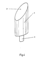
- control piston In the object according to the invention, the design of the control piston is of secondary importance. However, it must be ensured that the control elements can only assume two stable switching positions.
- the control valve shown in Fig. 4 represents a possible design of a usable control valve.
Landscapes
- Engineering & Computer Science (AREA)
- General Engineering & Computer Science (AREA)
- Mechanical Engineering (AREA)
- Fluid-Damping Devices (AREA)
- Vehicle Body Suspensions (AREA)
Applications Claiming Priority (2)
| Application Number | Priority Date | Filing Date | Title |
|---|---|---|---|
| DE3921819 | 1989-07-03 | ||
| DE3921819 | 1989-07-03 |
Publications (1)
| Publication Number | Publication Date |
|---|---|
| EP0406543A2 true EP0406543A2 (fr) | 1991-01-09 |
Family
ID=6384186
Family Applications (1)
| Application Number | Title | Priority Date | Filing Date |
|---|---|---|---|
| EP19900108971 Withdrawn EP0406543A2 (fr) | 1989-07-03 | 1990-05-12 | Réglage indépendant de la traction et de la pression pour amortisseurs hydrauliques |
Country Status (2)
| Country | Link |
|---|---|
| EP (1) | EP0406543A2 (fr) |
| JP (1) | JPH0366941A (fr) |
Cited By (4)
| Publication number | Priority date | Publication date | Assignee | Title |
|---|---|---|---|---|
| FR2677725A1 (fr) * | 1991-06-11 | 1992-12-18 | Atsugi Unisia Corp | Amortisseur hydraulique a tige de commande creuse. |
| DE10319390A1 (de) * | 2003-04-30 | 2004-11-25 | Thyssenkrupp Bilstein Gmbh | Hydraulischer Stoßdämpfer |
| DE102008043564A1 (de) * | 2008-11-07 | 2010-05-20 | Zf Friedrichshafen Ag | Schwingungsdämpfer mit einstellbarer Dämpfkraft |
| DE102020113576A1 (de) | 2020-05-19 | 2021-11-25 | BSS Baumann Sicherheitssysteme GmbH | Gas- oder Öldruckfeder |
-
1990
- 1990-04-03 JP JP8762090A patent/JPH0366941A/ja active Pending
- 1990-05-12 EP EP19900108971 patent/EP0406543A2/fr not_active Withdrawn
Cited By (6)
| Publication number | Priority date | Publication date | Assignee | Title |
|---|---|---|---|---|
| FR2677725A1 (fr) * | 1991-06-11 | 1992-12-18 | Atsugi Unisia Corp | Amortisseur hydraulique a tige de commande creuse. |
| US5307907A (en) * | 1991-06-11 | 1994-05-03 | Atsugi Unisia Corporation | Hydraulic damper |
| DE10319390A1 (de) * | 2003-04-30 | 2004-11-25 | Thyssenkrupp Bilstein Gmbh | Hydraulischer Stoßdämpfer |
| DE10319390B4 (de) * | 2003-04-30 | 2005-11-10 | Thyssenkrupp Bilstein Gmbh | Hydraulischer Stoßdämpfer |
| DE102008043564A1 (de) * | 2008-11-07 | 2010-05-20 | Zf Friedrichshafen Ag | Schwingungsdämpfer mit einstellbarer Dämpfkraft |
| DE102020113576A1 (de) | 2020-05-19 | 2021-11-25 | BSS Baumann Sicherheitssysteme GmbH | Gas- oder Öldruckfeder |
Also Published As
| Publication number | Publication date |
|---|---|
| JPH0366941A (ja) | 1991-03-22 |
Similar Documents
| Publication | Publication Date | Title |
|---|---|---|
| DE10126555C2 (de) | Dämpfungskraftregelnder Hydraulikstoßdämpfer | |
| DE3905639C2 (fr) | ||
| DE10257872B4 (de) | Hydraulischer Stoßdämpfer mit Dämpfungskraftsteuerung | |
| DE60114584T2 (de) | Schwingungsdämpfungssystem mit einem hydraulischen dämpfer, welcher über eine feldempfindliche flüssigkeit gesteuert wird | |
| DE19749356B4 (de) | Zweistufiger Stoßdämpfer mit hubabhängiger Dämpfung | |
| EP0405123B1 (fr) | Soupape électromagnétique à deux sens pour réglage d'une dérivation | |
| DE19948328B4 (de) | Schwingungsdämpfer mit zweistufiger Dämpfung | |
| DE19734522C2 (de) | Hydraulikstoßdämpfer mit einstellbarer Dämpfungskraft | |
| EP0602121B1 (fr) | Dispositif a soupape pilotable pour amortisseurs de vibrations bitubes reglables | |
| EP0435357B1 (fr) | Soupape de dérivation à caractéristiques variables pour amortisseurs de vibrations réglables | |
| DE3446133A1 (de) | Schwingungsdaempfer mit veraenderbarer daempfkraft | |
| DE4208886A1 (de) | Daempfkraftveraenderbarer schwingungsdaempfer mit notbetriebseinstellung | |
| EP0207409A2 (fr) | Système à clapets pour amortisseur hydraulique d'oscillations réglable | |
| DE3340153C2 (de) | Schwingungsdämpfende Befestigungsvorrichtung für eine Brennkraftmaschine | |
| DE3313613A1 (de) | Daempfungskraft-erzeugungsvorrichtung fuer einen oeldaempfer | |
| DE19805957A1 (de) | Verstellbarer Stoßdämpfer und Verfahren zum Verstellen der Dämpfungsrate eines Stoßdämpfers | |
| DE3742099A1 (de) | Hydraulischer daempfer | |
| EP0575379B1 (fr) | Amortisseur bitube | |
| DE19963415B4 (de) | Hydraulischer Stoßdämpfer mit Dämpfungskraftregelung | |
| DE966497C (de) | In beiden Richtungen arbeitendes Plattenventil fuer Fluessigkeitsstossdaempfer | |
| DE4137403A1 (de) | Zweirohr-stossdaempfer | |
| DE2745768A1 (de) | Hydraulischer stossdaempfer | |
| DE7346104U (de) | Stoßdämpfer | |
| EP1087153A1 (fr) | Dispositif pour l'augmentation de l'amortissement | |
| EP0406543A2 (fr) | Réglage indépendant de la traction et de la pression pour amortisseurs hydrauliques |
Legal Events
| Date | Code | Title | Description |
|---|---|---|---|
| PUAI | Public reference made under article 153(3) epc to a published international application that has entered the european phase |
Free format text: ORIGINAL CODE: 0009012 |
|
| AK | Designated contracting states |
Kind code of ref document: A2 Designated state(s): DE ES FR GB IT SE |
|
| ITCL | It: translation for ep claims filed |
Representative=s name: RICCARDI SERGIO & CO. |
|
| STAA | Information on the status of an ep patent application or granted ep patent |
Free format text: STATUS: THE APPLICATION HAS BEEN WITHDRAWN |
|
| 18W | Application withdrawn |
Withdrawal date: 19910410 |
|
| R18W | Application withdrawn (corrected) |
Effective date: 19910410 |