EP0405633A2 - Dispositif de mesure de pression/de pression différentielle - Google Patents
Dispositif de mesure de pression/de pression différentielle Download PDFInfo
- Publication number
- EP0405633A2 EP0405633A2 EP90201479A EP90201479A EP0405633A2 EP 0405633 A2 EP0405633 A2 EP 0405633A2 EP 90201479 A EP90201479 A EP 90201479A EP 90201479 A EP90201479 A EP 90201479A EP 0405633 A2 EP0405633 A2 EP 0405633A2
- Authority
- EP
- European Patent Office
- Prior art keywords
- pressure
- diaphragm
- low pressure
- stem
- plate
- Prior art date
- Legal status (The legal status is an assumption and is not a legal conclusion. Google has not performed a legal analysis and makes no representation as to the accuracy of the status listed.)
- Granted
Links
Images


Classifications
-
- G—PHYSICS
- G01—MEASURING; TESTING
- G01L—MEASURING FORCE, STRESS, TORQUE, WORK, MECHANICAL POWER, MECHANICAL EFFICIENCY, OR FLUID PRESSURE
- G01L13/00—Devices or apparatus for measuring differences of two or more fluid pressure values
- G01L13/02—Devices or apparatus for measuring differences of two or more fluid pressure values using elastically-deformable members or pistons as sensing elements
- G01L13/025—Devices or apparatus for measuring differences of two or more fluid pressure values using elastically-deformable members or pistons as sensing elements using diaphragms
-
- G—PHYSICS
- G01—MEASURING; TESTING
- G01L—MEASURING FORCE, STRESS, TORQUE, WORK, MECHANICAL POWER, MECHANICAL EFFICIENCY, OR FLUID PRESSURE
- G01L15/00—Devices or apparatus for measuring two or more fluid pressure values simultaneously
-
- G—PHYSICS
- G01—MEASURING; TESTING
- G01L—MEASURING FORCE, STRESS, TORQUE, WORK, MECHANICAL POWER, MECHANICAL EFFICIENCY, OR FLUID PRESSURE
- G01L19/00—Details of, or accessories for, apparatus for measuring steady or quasi-steady pressure of a fluent medium insofar as such details or accessories are not special to particular types of pressure gauges
- G01L19/0007—Fluidic connecting means
- G01L19/0046—Fluidic connecting means using isolation membranes
-
- G—PHYSICS
- G01—MEASURING; TESTING
- G01L—MEASURING FORCE, STRESS, TORQUE, WORK, MECHANICAL POWER, MECHANICAL EFFICIENCY, OR FLUID PRESSURE
- G01L9/00—Measuring steady of quasi-steady pressure of fluid or fluent solid material by electric or magnetic pressure-sensitive elements; Transmitting or indicating the displacement of mechanical pressure-sensitive elements, used to measure the steady or quasi-steady pressure of a fluid or fluent solid material, by electric or magnetic means
- G01L9/0041—Transmitting or indicating the displacement of flexible diaphragms
- G01L9/0051—Transmitting or indicating the displacement of flexible diaphragms using variations in ohmic resistance
- G01L9/0052—Transmitting or indicating the displacement of flexible diaphragms using variations in ohmic resistance of piezoresistive elements
- G01L9/0054—Transmitting or indicating the displacement of flexible diaphragms using variations in ohmic resistance of piezoresistive elements integral with a semiconducting diaphragm
Definitions
- the subject invention relates to pressure/differential pressure measuring devices and more particularly to such devices capable of accurately measuring low differential pressures in the presence of high static line pressures and simultaneously measuring the static pressure.
- U.S Patent No. 4,135,408, DiGiovanni - Differential pressure Measuring Transducer Assembly discloses a differential pressure unit having isolation diaphragms with overpressure nesting and a silicon piezoresistive pressure sensor mounted on a range diaphragm for movement therewith.
- Foxboro has placed a separate static pressure transducer on a differential pressure sensor.
- Honeywell has a unit with overpressure protection which utilizes a valve and piezoresistive sensors.
- Another object of the invention is to protect the differential pressure sensor from being exposed to high differential pressures regardless of the side to which the pressure is applied.
- a pressure/differential pressure measuring device having a range plate with static and differential pressure sensors mounted therein.
- a high pressure isolation plate is mounted on one side of the range plate and a low pressure on the other.
- a high pressure diaphragm is mounted on the side of the high pressure isolation plate away from the range plate and sealed thereto.
- a low pressure diaphragm is mounted on the side of the low pressure isolation plate away from the range plate and sealed thereto.
- First and second fluid chambers are formed between the high pressure diaphragm and the high pressure isolation plate side of the sensor assemblies and the low pressure diaphragm and the low pressure isolation plate side of the sensor assemblies.
- a conduit is formed between the first and second fluid chambers with a range diaphragm mounted at the conduit isolating the first and second chambers. Means are provided to apply high and low pressure to the outside of the high and low pressure diaphragms respectively.
- one side of the range plate has the range diaphragm mounted thereon and a fourth diaphragm is mounted on the range plate with a conduit running from the first fluid chamber to its high pressure side.
- the fourth diaphragm is normally seated and not movable as long as the pressure on the high pressure side remains higher than the pressure on the low pressure side but is capable of movement if the pressure on the low pressure side should exceed that on the high pressure side until such time as the low pressure diaphragm is seated.
- the pressure sensors employ piezoresistive sensor chips mounted on chip carriers with a hollow stem bonded to the side of the chip carrier away from the chip.
- the chip carrier and the stem are made of a material to minimize thermal expansion effects on the sensitivity of the sensor.
- the static sensor chip has a vacuum on its underside between it and the chip carrier. In the differential pressure sensor, and aperture extends through the chip carrier leading to the hollow stem so that the low pressure may be applied to the underside of the chip while the high pressure is applied to the upperside.
- the subject invention relates to a pressure/differential pressure measuring device contained in a single capsule and capable of accurately measuring low differential pressures in the presence of high static line pressures while measuring static pressures separately.
- the device provide protection to the pressure sensors from being exposed to high pressures.
- the pressure sensing elements are of the piezoresistive type. A simple three or four diaphragm capsule design is employed with gross over pressure protection in two directions.
- the capsule is made up of three major parts. Referring to FIG. 1, it employs a low pressure isolation plate 10, a high pressure isolation plate 12, and a range plate 14. A high pressure isolation diaphragm 16 is mounted on the high pressure side of plate 12. A low pressure diaphragm shown at 26 in FIG. 2 is mounted on the opposite side of plate 10. A range diaphragm 18 is mounted on the high pressure side of range plate 14. Electrical connections are made to the sensors through a connector stem 20 with the leads 22 being taken out of the hole 23 in range plate 14.
- FIG. 2 there is shown a cross section of the assembly of FIG. 1 taken along the lines A-A.
- the high pressure isolation plate 12 is shown with the diaphragm 16 joined thereto and forming a chamber 24 between it and the isolation plate 12.
- the low pressure isolation plate 10 has a diaphragm 26 joined thereto and forming a chamber 28 between it and the isolation plate 10.
- the range diaphragm 18 is mounted at the high pressure side of a conduit 30 which extends between a series of conduits 32 going from the low pressure isolation chamber 28 to the underside of differential pressure sensor 34 and static pressure sensor 36.
- the chamber 24 on the high pressure side goes through a series of conduits 38 to the high pressure side of the range diaphragm 18 and the high pressure side of sensor assemblies 34 and 36.
- a hermetically sealed header 40 is used to take the leads from the sensor chips 42 and 44 outside the measuring device.
- FIG. 3 a typical isolation diaphragm for either the high or low pressure side is illustrated.
- the diaphragm 16, 26 defines a chamber 24, 28 between it and isolation plate 10, 12.
- Over-pressure nesting protection is provided by seat 46 against which diaphragms 16 or 26 nest When pressure is sufficient to do so stopping the application of additional pressure against the sensors and preventing the rupture of the sensor chips 42 and 44.
- FIG. 4 illustrates the differential pressure sensor assembly having sensor chip 42 mounted on a chip carrier 48.
- This embodiment shows a hollow glass stem 50 bonded to the underside of chip 48 at 52.
- a stainless steel stem mount 54 is bonded to glass stem 50 sufficiently far down the glass stem to minimize thermal expansion effects and may be joined on its other end 56 to the low pressure side of the range plate 14. It can be seen that there is an aperture 58 through the center of the chip carrier 48 which is in line with the hollow portion 60 of the glass stem 50 and the hollow portion 62 of the stainless steel stem mount 54 such that low pressure may be applied against the bottom of sensor chip 42 via the conduits 32.
- the static pressure sensor in FIG. 5 is the same as the differential pressure sensor of FIG. 4 except that there is no hole 58 in the static chip carrier 61 instead there is a vacuum in the chamber 63 so that the static pressure may be measured between the outside of chip 44 which is at the pressure in conduits 38 and the vacuum.
- the stems of sensor assemblies 34 and 36 are preferably of materials recited above. However, ceramic materials may be used in place of glass and in some instances, also for chip carriers 48 and 61 and stem mounts 54, as long as the combination of materials sufficiently minimizes the thermal expansion effects on the sensitivity of the sensors.
- FIG. 6 there is shown a top view of the range plate 14 having range diaphragm 18 mounted thereon. The tops of the sensor chips 42 and 44 are shown.
- FIG. 7 a partial cross section at B-B in FIG. 6 is shown illustrating the mounting of the static sensor assembly having a strain gauge barrier 45 mounted on the chip carrier 61 with glass stem 50 extending downward through the hole 64 in range plate 14.
- the vacuum chamber 63 is shown between the strain gauge barrier 45 and the chip carrier 60.
- FIG. 8 which is taken as detail A of FIG. 6, the differential pressure chip 42 and the static pressure chip 44 are shown interconnected to the hermetic seal connector through contacts 66.
- FIG. 9 shows the configuration of the bridge sensors on chips 42 and 44 with a one milliamp input at terminal 66 and output across terminals 68 and 70. Return and zero compensation are provided across terminals 72 and 74.
- the resistive elements 75, 76, 78 and 80 form the arms of a wheatstone bridge.
- the configuration of these elements on the chips 42 and 44 can best be seen by referring to FIG. 10 where the configuration of the piezoresistive elements is such that when pressure is exerted downward on the diaphragm 82, elements 75 and 80 are placed in what is called compression because their resistance goes down whereas elements 76 and 78 are placed in what is called tension because their resistance goes up. This is because the long legs of the elements 76 and 78 are radial whereas the long legs of the elements 75 and 80 run generally perpendicular to the radius of the diaphragm 82.
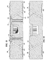
- FIG. 11 illustrates the assembly in an exploded isometric view showing the high and low pressure process flanges 84 and 88 which are sealed to the capsule 90 which is comprised of the range plate 14 and high and low pressure isolation plates 12 and respectively by seal O rings 92.
- Fill plugs 94 are used to seal the fill plug conduit 96 of the low pressure side and 98 of the high pressure side shown in FIG. 1 through which the low pressure side 32 and high pressure side 38 of the assembly shown in FIG. 2 are filled with fluid.
- the internal space between the two isolation diaphragms 16 and 26 is divided almost in half by the range diaphragm 18. Pressure applied to each isolation diaphragm via the process flanges 84 and 88 shown in FIG. 11 is transferred to the pressure sensors through the fill fluid.
- the differential pressure sensor has exposure to both pressure chambers via channels 32 and 38 of FIG. 2 such that the net pressure developed across it is almost equal to the difference in pressure applied between the low and high pressure sides of the capsule.
- the static pressure sensor measures absolute pressure and has exposure to the high pressure side 38 only, with its backside evacuated.
- the sensors are of the piezoresistive type and operate on the principal of change of electrical resistance with pressure.
- each sensor On each sensor a thin diaphragm has been formed by a selective etching process as shown in FIG. 10.
- the pressure induced stresses on the diaphragm are sensed by the four piezoresistors 75, 76, 78 and 80 placed on the diaphragm 82 in the form of the wheatstone bridge shown in FIG. 9.
- Output of a properly excited bridge is proportional to the differential pressure developed across the sensor.
- the sensor assemblies shown in FIGs. 4 and 5 are configured as described to minimize the mounting effects. It also reduces static pressure and temperature sensitivity on the differential sensor assembly and the equivalent on the static sensor. Both sensor outputs are carried out through the hermetically sealed header 40 shown in FIG. 2 which is mounted on the range plate 14.
- the range diaphragm 18, also mounted on the range plate 14, controls the maximum pressure developed between the high and low pressure chambers.
- the range diaphragm as a pressure summing element responds to differential pressure across it by moving in the direction of low pressure and in doing so displaces a volume proportional to its effective surface area and its travel.
- the range diaphragm is designed to have a linear volumetric displacement as a function of pressure within its rated pressure range. As the range diaphragm 18 moves it withdraws liquid from the backside of the isolation diaphragm 16 which is at higher pressure. Without the liquid support the isolation diaphragm 16 is drawn into its corresponding nesting plate 46 shown in FIG. 3.
- range diaphragm 18 and the isolation diaphragm 16 When the excessive over pressure is removed from the capsule, energy stored in the range diaphragm 18 and the isolation diaphragm 16 would facilitate the release of the high pressure side isolation diaphragm 16 from its nesting plate 46.
- suitable static and differential pressure sensors and a range of diaphragms may be selected. The rest of the parts are common between capsules. Two or three range diaphragms would cover most of the differential pressure ranges commonly measured in the industry.
- FIG. 12 illustrates a top view of the embodiment, range plate 96 having a range diaphragm 98 and differential pressure and static pressure sensors 42 and 44 respectively.
- FIG. 13 is a section through FIG. 12 taken along lines A-A and shows two conduits 100 and 102 which extend from a fourth diaphragm 104 upward to the sensors through hole 106 and 108 shown in FIG. 12 as well.
- Diaphragm 104 is normally seated against its pressure isolation plate (not shown) and is free to move into space 105 and displace fluid therein if the pressure on its underside becomes higher than that on its upper side but will not seat against the range plate 96 because the low pressure diaphragm 26 will seat first.
- FIG. 14 shows a cross section of FIG. 12 taken along line E-E showing two additional conduits 110 and 112 going from the underside of range diaphragm 98 to the low pressure side of the sensors 42 and 44.
- Fourth diaphragm 104 is normally seated against the low pressure isolation plate (not shown) and not movable as long as the pressure on the high pressure side remains higher than the pressure on the low pressure side but is capable of movement if the pressure on the low pressure side should exceed that on the high pressure side until such time as the low pressure diaphragm 26 is seated. This is to accept oil from the diaphragm 26 on the low pressure side to protect the sensor chip from overpressure because the sensor chip is more susceptible to damage from overpressure on the low pressure side.
Applications Claiming Priority (2)
| Application Number | Priority Date | Filing Date | Title |
|---|---|---|---|
| US07/371,346 US4909083A (en) | 1989-06-26 | 1989-06-26 | Pressure/differential pressure measuring device |
| US371346 | 1995-01-11 |
Publications (3)
| Publication Number | Publication Date |
|---|---|
| EP0405633A2 true EP0405633A2 (fr) | 1991-01-02 |
| EP0405633A3 EP0405633A3 (en) | 1991-07-31 |
| EP0405633B1 EP0405633B1 (fr) | 1994-05-18 |
Family
ID=23463590
Family Applications (1)
| Application Number | Title | Priority Date | Filing Date |
|---|---|---|---|
| EP90201479A Expired - Lifetime EP0405633B1 (fr) | 1989-06-26 | 1990-06-08 | Dispositif de mesure de pression/de pression différentielle |
Country Status (5)
| Country | Link |
|---|---|
| US (1) | US4909083A (fr) |
| EP (1) | EP0405633B1 (fr) |
| JP (1) | JP2799761B2 (fr) |
| CA (1) | CA2019731C (fr) |
| DE (1) | DE69008936T2 (fr) |
Cited By (3)
| Publication number | Priority date | Publication date | Assignee | Title |
|---|---|---|---|---|
| WO1994021992A1 (fr) * | 1993-03-15 | 1994-09-29 | Siemens Aktiengesellschaft | Convertisseur de mesure de pression differentielle |
| WO2000003220A1 (fr) * | 1998-07-09 | 2000-01-20 | Honeywell Inc. | Procedes et appareil permettant de detecter une pression differentielle et une pression statique de jauge dans un conduit d'ecoulement de fluide |
| US7629359B2 (en) | 2004-07-01 | 2009-12-08 | L'oreal | Use of piperidine derivatives as dermo-decontracting agents |
Families Citing this family (9)
| Publication number | Priority date | Publication date | Assignee | Title |
|---|---|---|---|---|
| US5029479A (en) * | 1988-08-15 | 1991-07-09 | Imo Industries, Inc. | Differential pressure transducers |
| US5022270A (en) * | 1989-06-15 | 1991-06-11 | Rosemount Inc. | Extended measurement capability transmitter having shared overpressure protection means |
| US5680109A (en) * | 1996-06-21 | 1997-10-21 | The Foxboro Company | Impulse line blockage detector systems and methods |
| JP4419847B2 (ja) * | 2004-09-16 | 2010-02-24 | 株式会社デンソー | 圧力センサ |
| US7833211B2 (en) * | 2006-04-24 | 2010-11-16 | The Procter & Gamble Company | Stretch laminate, method of making, and absorbent article |
| US7578194B1 (en) * | 2008-02-11 | 2009-08-25 | Sensata Technologies, Inc. | Differential fluid pressure measurement apparatus |
| EP2931334B1 (fr) | 2012-12-14 | 2017-08-09 | Gambro Lundia AB | Repositionnement de diaphragme pour une capsule de pression à l'aide d'une détection de position |
| CN103048086B (zh) * | 2012-12-28 | 2016-04-06 | 宜昌兆峰自动化仪表有限责任公司 | 一种活塞式磁跟随差压指示计 |
| JP7401249B2 (ja) * | 2019-10-09 | 2023-12-19 | アズビル株式会社 | センサ素子 |
Citations (6)
| Publication number | Priority date | Publication date | Assignee | Title |
|---|---|---|---|---|
| US4135408A (en) * | 1976-03-24 | 1979-01-23 | Ict Instruments, Inc. | Differential pressure measuring transducer assembly |
| GB2080541A (en) * | 1980-07-18 | 1982-02-03 | Hitachi Ltd | Semiconductor pressure transducer |
| EP0080186A2 (fr) * | 1981-11-20 | 1983-06-01 | Hitachi, Ltd. | Transducteur de pression à semi-conducteurs |
| EP0091396A1 (fr) * | 1982-04-06 | 1983-10-12 | Siemens Aktiengesellschaft | Convertisseur de mesure de pression ou de différence de pression |
| US4712082A (en) * | 1985-03-25 | 1987-12-08 | Nippon Soken, Inc. | Pressure sensor |
| JPS638524A (ja) * | 1986-06-30 | 1988-01-14 | Yamatake Honeywell Co Ltd | 差圧発信器 |
Family Cites Families (1)
| Publication number | Priority date | Publication date | Assignee | Title |
|---|---|---|---|---|
| US1018561A (en) * | 1910-10-12 | 1912-02-27 | Embury A Hitchcock | Meter. |
-
1989
- 1989-06-26 US US07/371,346 patent/US4909083A/en not_active Expired - Fee Related
-
1990
- 1990-06-08 EP EP90201479A patent/EP0405633B1/fr not_active Expired - Lifetime
- 1990-06-08 DE DE69008936T patent/DE69008936T2/de not_active Expired - Fee Related
- 1990-06-25 CA CA002019731A patent/CA2019731C/fr not_active Expired - Fee Related
- 1990-06-26 JP JP2165826A patent/JP2799761B2/ja not_active Expired - Lifetime
Patent Citations (7)
| Publication number | Priority date | Publication date | Assignee | Title |
|---|---|---|---|---|
| US4135408A (en) * | 1976-03-24 | 1979-01-23 | Ict Instruments, Inc. | Differential pressure measuring transducer assembly |
| GB2080541A (en) * | 1980-07-18 | 1982-02-03 | Hitachi Ltd | Semiconductor pressure transducer |
| EP0080186A2 (fr) * | 1981-11-20 | 1983-06-01 | Hitachi, Ltd. | Transducteur de pression à semi-conducteurs |
| EP0091396A1 (fr) * | 1982-04-06 | 1983-10-12 | Siemens Aktiengesellschaft | Convertisseur de mesure de pression ou de différence de pression |
| US4712082A (en) * | 1985-03-25 | 1987-12-08 | Nippon Soken, Inc. | Pressure sensor |
| JPS638524A (ja) * | 1986-06-30 | 1988-01-14 | Yamatake Honeywell Co Ltd | 差圧発信器 |
| US4841776A (en) * | 1986-06-30 | 1989-06-27 | Yamatake-Honeywell Co., Ltd. | Differential pressure transmitter |
Cited By (4)
| Publication number | Priority date | Publication date | Assignee | Title |
|---|---|---|---|---|
| WO1994021992A1 (fr) * | 1993-03-15 | 1994-09-29 | Siemens Aktiengesellschaft | Convertisseur de mesure de pression differentielle |
| US5596148A (en) * | 1993-03-15 | 1997-01-21 | Siemens Aktiengesellschaft | Pressure difference measurement transducer with electric lead-through in bore parallel to housing longitudinal axis |
| WO2000003220A1 (fr) * | 1998-07-09 | 2000-01-20 | Honeywell Inc. | Procedes et appareil permettant de detecter une pression differentielle et une pression statique de jauge dans un conduit d'ecoulement de fluide |
| US7629359B2 (en) | 2004-07-01 | 2009-12-08 | L'oreal | Use of piperidine derivatives as dermo-decontracting agents |
Also Published As
| Publication number | Publication date |
|---|---|
| JPH03115943A (ja) | 1991-05-16 |
| DE69008936T2 (de) | 1994-09-01 |
| CA2019731A1 (fr) | 1990-12-26 |
| EP0405633B1 (fr) | 1994-05-18 |
| CA2019731C (fr) | 1999-01-19 |
| DE69008936D1 (de) | 1994-06-23 |
| EP0405633A3 (en) | 1991-07-31 |
| JP2799761B2 (ja) | 1998-09-21 |
| US4909083A (en) | 1990-03-20 |
Similar Documents
| Publication | Publication Date | Title |
|---|---|---|
| US5483834A (en) | Suspended diaphragm pressure sensor | |
| US4364276A (en) | Differential pressure measuring transducer assembly | |
| EP0164413B1 (fr) | Transducteur de pression | |
| US4135408A (en) | Differential pressure measuring transducer assembly | |
| CA1223453A (fr) | Sonde de manometrie a limiteur de surpression substantiellement plan pour le diaphragme capteur | |
| US4399707A (en) | Stress sensitive semiconductor unit and housing means therefor | |
| US6351996B1 (en) | Hermetic packaging for semiconductor pressure sensors | |
| US5012677A (en) | Differential pressure transmitter | |
| EP0316343B1 (fr) | Capteurs de pression isoles du milieu de pression | |
| EP0405633B1 (fr) | Dispositif de mesure de pression/de pression différentielle | |
| EP2128583A2 (fr) | Appareil capteur de pression | |
| US4086815A (en) | Device for use in sensing pressures | |
| US6041659A (en) | Methods and apparatus for sensing differential and gauge static pressure in a fluid flow line | |
| US4600912A (en) | Diaphragm pressure sensor with improved tensile loading characteristics | |
| JPS59125032A (ja) | 差圧測定装置 | |
| JPS59145940A (ja) | 差圧・圧力伝送器 | |
| US4140023A (en) | Differential pressure transducer | |
| US11359985B2 (en) | Oil filled transducers with isolated compensating capsule | |
| JPH04370726A (ja) | 半導体圧力センサ | |
| JPH05172676A (ja) | 差圧測定装置 | |
| JPH04320939A (ja) | 差圧伝送器 | |
| JPH05346363A (ja) | 差圧伝送器 | |
| JPH04319636A (ja) | 差圧伝送器 |
Legal Events
| Date | Code | Title | Description |
|---|---|---|---|
| PUAI | Public reference made under article 153(3) epc to a published international application that has entered the european phase |
Free format text: ORIGINAL CODE: 0009012 |
|
| AK | Designated contracting states |
Kind code of ref document: A2 Designated state(s): DE FR GB IT SE |
|
| PUAL | Search report despatched |
Free format text: ORIGINAL CODE: 0009013 |
|
| AK | Designated contracting states |
Kind code of ref document: A3 Designated state(s): DE FR GB IT SE |
|
| 17P | Request for examination filed |
Effective date: 19910831 |
|
| 17Q | First examination report despatched |
Effective date: 19921202 |
|
| GRAA | (expected) grant |
Free format text: ORIGINAL CODE: 0009210 |
|
| AK | Designated contracting states |
Kind code of ref document: B1 Designated state(s): DE FR GB IT SE |
|
| REF | Corresponds to: |
Ref document number: 69008936 Country of ref document: DE Date of ref document: 19940623 |
|
| ET | Fr: translation filed | ||
| ITF | It: translation for a ep patent filed |
Owner name: BUGNION S.P.A. |
|
| EAL | Se: european patent in force in sweden |
Ref document number: 90201479.4 |
|
| PLBE | No opposition filed within time limit |
Free format text: ORIGINAL CODE: 0009261 |
|
| STAA | Information on the status of an ep patent application or granted ep patent |
Free format text: STATUS: NO OPPOSITION FILED WITHIN TIME LIMIT |
|
| 26N | No opposition filed | ||
| PGFP | Annual fee paid to national office [announced via postgrant information from national office to epo] |
Ref country code: SE Payment date: 19990629 Year of fee payment: 10 |
|
| PG25 | Lapsed in a contracting state [announced via postgrant information from national office to epo] |
Ref country code: SE Free format text: LAPSE BECAUSE OF NON-PAYMENT OF DUE FEES Effective date: 20000609 |
|
| PGFP | Annual fee paid to national office [announced via postgrant information from national office to epo] |
Ref country code: FR Payment date: 20000615 Year of fee payment: 11 |
|
| EUG | Se: european patent has lapsed |
Ref document number: 90201479.4 |
|
| PGFP | Annual fee paid to national office [announced via postgrant information from national office to epo] |
Ref country code: GB Payment date: 20010606 Year of fee payment: 12 |
|
| PGFP | Annual fee paid to national office [announced via postgrant information from national office to epo] |
Ref country code: DE Payment date: 20010829 Year of fee payment: 12 |
|
| REG | Reference to a national code |
Ref country code: GB Ref legal event code: IF02 |
|
| PG25 | Lapsed in a contracting state [announced via postgrant information from national office to epo] |
Ref country code: FR Free format text: LAPSE BECAUSE OF NON-PAYMENT OF DUE FEES Effective date: 20020228 |
|
| PG25 | Lapsed in a contracting state [announced via postgrant information from national office to epo] |
Ref country code: GB Free format text: LAPSE BECAUSE OF NON-PAYMENT OF DUE FEES Effective date: 20020608 |
|
| PG25 | Lapsed in a contracting state [announced via postgrant information from national office to epo] |
Ref country code: DE Free format text: LAPSE BECAUSE OF NON-PAYMENT OF DUE FEES Effective date: 20030101 |
|
| GBPC | Gb: european patent ceased through non-payment of renewal fee |
Effective date: 20020608 |
|
| PG25 | Lapsed in a contracting state [announced via postgrant information from national office to epo] |
Ref country code: IT Free format text: LAPSE BECAUSE OF NON-PAYMENT OF DUE FEES;WARNING: LAPSES OF ITALIAN PATENTS WITH EFFECTIVE DATE BEFORE 2007 MAY HAVE OCCURRED AT ANY TIME BEFORE 2007. THE CORRECT EFFECTIVE DATE MAY BE DIFFERENT FROM THE ONE RECORDED. Effective date: 20050608 |