EP0405629A2 - Vorrichtung zum Zuordnen eines Beschreibungs-Einsatzstücks mit seinem BehÀ¤lter für Videokassetten - Google Patents
Vorrichtung zum Zuordnen eines Beschreibungs-Einsatzstücks mit seinem BehÀ¤lter für Videokassetten Download PDFInfo
- Publication number
- EP0405629A2 EP0405629A2 EP90201444A EP90201444A EP0405629A2 EP 0405629 A2 EP0405629 A2 EP 0405629A2 EP 90201444 A EP90201444 A EP 90201444A EP 90201444 A EP90201444 A EP 90201444A EP 0405629 A2 EP0405629 A2 EP 0405629A2
- Authority
- EP
- European Patent Office
- Prior art keywords
- descriptive
- cases
- insert
- conveyor
- plates
- Prior art date
- Legal status (The legal status is an assumption and is not a legal conclusion. Google has not performed a legal analysis and makes no representation as to the accuracy of the status listed.)
- Withdrawn
Links
- 241000252254 Catostomidae Species 0.000 claims description 16
- 241001482320 Trachemys Species 0.000 claims 1
- 241001482322 Trachemys scripta Species 0.000 claims 1
- 238000003780 insertion Methods 0.000 description 5
- 230000037431 insertion Effects 0.000 description 5
- 229920003023 plastic Polymers 0.000 description 4
- 239000002985 plastic film Substances 0.000 description 3
- 230000014759 maintenance of location Effects 0.000 description 2
- 230000000717 retained effect Effects 0.000 description 2
- 238000004519 manufacturing process Methods 0.000 description 1
- 238000012986 modification Methods 0.000 description 1
- 230000004048 modification Effects 0.000 description 1
Images

Classifications
-
- G—PHYSICS
- G11—INFORMATION STORAGE
- G11B—INFORMATION STORAGE BASED ON RELATIVE MOVEMENT BETWEEN RECORD CARRIER AND TRANSDUCER
- G11B23/00—Record carriers not specific to the method of recording or reproducing; Accessories, e.g. containers, specially adapted for co-operation with the recording or reproducing apparatus ; Intermediate mediums; Apparatus or processes specially adapted for their manufacture
- G11B23/02—Containers; Storing means both adapted to cooperate with the recording or reproducing means
- G11B23/023—Containers for magazines or cassettes
-
- G—PHYSICS
- G11—INFORMATION STORAGE
- G11B—INFORMATION STORAGE BASED ON RELATIVE MOVEMENT BETWEEN RECORD CARRIER AND TRANSDUCER
- G11B23/00—Record carriers not specific to the method of recording or reproducing; Accessories, e.g. containers, specially adapted for co-operation with the recording or reproducing apparatus ; Intermediate mediums; Apparatus or processes specially adapted for their manufacture
- G11B23/38—Visual features other than those contained in record tracks or represented by sprocket holes the visual signals being auxiliary signals
- G11B23/40—Identifying or analogous means applied to or incorporated in the record carrier and not intended for visual display simultaneously with the playing-back of the record carrier, e.g. label, leader, photograph
Definitions
- Videocassettes ie cartridges containing two spools of magnetic tape for use in video cameras and video players, are stored in substantially book-shaped cases consisting of two half-books hinged to a spine.
- the cases are mass produced, and are personalized by inserting below the transparent plastic sheet a printed descriptive insert carrying the title of the videocassette contents and other information.
- the object of the present invention is to automatically insert said descriptive insert, an operation which is currently done manually, with all the consequent limitations in terms of production and cost.
- the present invention therefore provides a device for attaining the aforesaid object.
- Said device comprises conveyor means driven with intermittent motion and arranged to receive and transfer the open book-shaped cases with their cavity for receiving the videocassette facing upwards, and their spine perpendicular to the conveyor axis.
- the operating station for inserting the descriptive inserts is positioned along said conveyor, which connects together a stock of empty cases and a stock of cases containing the videocassette and with the descriptive insert already applied.
- Said station comprises sucker means positioned respectively above and below the conveyor and arranged to raise the spine of the case upwards and to pull the transparent plastic sheet downwards.
- the station comprises the means for inserting the descriptive insert, which consist of two coplanar plates of adjustable distance apart, driven with to-and-fro movement parallel to the spine of the book-shaped case.
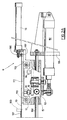
- FIGSaid figures, and in particular Figure 1 show a conveying line 1 for the cases 2, it being shown schematically as it can take the form of any conveyor suitable for the purpose, such as a belt conveyor, slat conveyor or V-belt conveyor.
- the conveyor 1 connects a store of empty cases (to the left in Figure 1) to a store of full cases (to the right in Figure 1), neither of which is shown for simplicity and clarity.
- To the side of said conveyor 1 there are located convenient devices, not shown because of known type, for feeding the descriptive inserts 3 to be associated with the cases 2, the videocassettes 4 to be placed in the cases, and seals (not shown) to be applied to the filled cases.
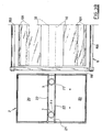
- the cases 2 consist of a hollow synthetic thin-walled structure comprising two half-cases 20 hinged together in the manner of a book by a central rib 21 (see also Figure 3B) with two creasing lines 22, defining the spine.
- the conveyor can move with stepwise motion, or intermittently, for example under the control of a sensor 5 ( Figure 1) such as a photoelectric cell, by which the arriving cases 2 are correctly positioned relative to the device for inserting the descriptive inserts 3.
- a sensor 5 Figure 1 such as a photoelectric cell
- the open cases 2 have their rib 21 positioned transversely to the conveyor 1, this latter having a width less than the width of the rib (see Figures 1, 2B).
- the device 6 for inserting the descriptive inserts 3 is positioned in the insertion station on one side of the conveyol 1 (see Figures 1, 2A), on the other side of which, facing this device, there is provided a gripper device 66 (see Figures 1, 2B).
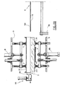
- suckers 7 and 77 which are positioned respectively above and below the outward portion of the conveyor 1, to the sides thereof.
- FIGs 2B and 4 in the specific case illustrated there are two upper suckers 7 and two lower suckers 77, spaced a distance apart exceeding the width of the conveyor 1. Said pairs of suckers are aligned vertically and are connected to a convenient pneumatic circuit. It is apparent that the number of upper or lower suckers can be different from that shown, particularly if the cases are not provided with the central rib 21.
- the upper suckers 7 raise the cast 2 via the rib 21, and the lower suckers 77 keep the sheet 23 separated from the case.
- the two half-cases 20 are opened through an angle exceeding 180°, and the sheet is bent in the opposite direction to the case.
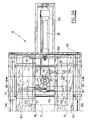
- the lever system comprises a central rocker lever 13 which is pivoted to an underlying slider 15 ( Figures 2A, 3A, 4), and to which there are hinged two opposing connecting rods 14 connected to the slides 11.
- the slider 15 supports the bars 110 on which the slides 11 slide, said slider being slidable along respective horizontal bars 150 positioned perpendicular to the direction of advancement of the cases 2.
- the bars 150 are supported on the structure 99 of the insertion device 6, to which structure 99 there is hinged the cylinder-piston unit 151 which drives the slider 15 (see Figures 2A, 3A), to the rear end of this latter there being fixed the cylinder-piston unit 16 for driving a pusher 160.
- This latter consists of a plate positioned transversely to the plates 10 and lowerly comprises two projections 161 inserted through corresponding rear longitudinal apertures 100 ( Figures 2A, 3A, 4) provided in the underlying plates 10.
- the apertures 100 lie above corresponding recesses 111 provided in the underlying slides 11, the width of said apertures 100 and recesses 111 being such as to allow the slides 11 to approach and withdraw from each other, as stated.
- the plates 10 extend projectingly beyond the slider 15 and towards the conveyor 1 by a length substantially equal to the width of the descriptive inserts 3. Finally, said projecting parts of the plates have their outer longitudinal edges 101 bent inwards by substantially 180° as shown in Figures 2B, 3B, 4, to form two retention and slide seats for the corresponding edges of the descriptive inserts, as will be apparent hereinafter.
- the pusher 161 then advances and pushes the descriptive inserts between the two bent retention sheets 101, after which the two slides 11 approach each other such that the descriptive insert is obliged to rise in its centre, seeing that its side edges are engaged in the seats 101.
- the cylinder-piston unit 151 receives the signal to advance the slider 15, with simultaneous insertion of the plates 10 between the sheet 23 and the half-cases 20 (position shown by dashed and dotted lines in Figure 4).
- the plates 10 then retract (position shown by full lines in Figure 4), and the gripper device 66 (see Figure 2B), substantially in the form of a clamp, firstly advances so that its jaws embrace the front ends of the descriptive insert 3 and sheet 23, and then clamps these ends.
- the unit 66 can be formed to retain only the descriptive insert 3 during the retraction of the plates 10, as the case 2 is retained by the suckers 7 and 77.
- the plates 10 retract into the position for loading a further descriptive insert 3 ( Figure 3A).
- the device 66 then opens and returns to its rest position ( Figure 2B).
- the suckers 7 and 77 then approach each other to substantially the level of the conveyor, where the vacuum is broken.
- the suckers then again withdraw from each other and the conveyor advances through one step, and a new cycle restarts.
- the descriptive insert 3 can be retained by a slidable vertical rod positioned to the side of the upper suckers 7 on the same side as the device 6, to be lowered for insertion into the gap between the facing edges of the plates 10 (see Figure 3B).
Landscapes
- Collation Of Sheets And Webs (AREA)
Applications Claiming Priority (2)
| Application Number | Priority Date | Filing Date | Title |
|---|---|---|---|
| IT4684789 | 1989-06-19 | ||
| IT8946847A IT1234154B (it) | 1989-06-19 | 1989-06-19 | Dispostivo per associare locandine a cassette per videonastri |
Publications (2)
| Publication Number | Publication Date |
|---|---|
| EP0405629A2 true EP0405629A2 (de) | 1991-01-02 |
| EP0405629A3 EP0405629A3 (en) | 1992-02-19 |
Family
ID=11259626
Family Applications (1)
| Application Number | Title | Priority Date | Filing Date |
|---|---|---|---|
| EP19900201444 Withdrawn EP0405629A3 (en) | 1989-06-19 | 1990-06-06 | Device for associating descriptive inserts with cases for video cassettes |
Country Status (2)
| Country | Link |
|---|---|
| EP (1) | EP0405629A3 (de) |
| IT (1) | IT1234154B (de) |
Cited By (1)
| Publication number | Priority date | Publication date | Assignee | Title |
|---|---|---|---|---|
| EP0540078A3 (en) * | 1991-10-30 | 1994-06-22 | Sacma Plast Srl | Unit for associating sleeves with videocassette cases |
Family Cites Families (1)
| Publication number | Priority date | Publication date | Assignee | Title |
|---|---|---|---|---|
| US4555290A (en) * | 1984-04-19 | 1985-11-26 | Blair Industries, Inc. | Method of making cassette holders |
-
1989
- 1989-06-19 IT IT8946847A patent/IT1234154B/it active
-
1990
- 1990-06-06 EP EP19900201444 patent/EP0405629A3/en not_active Withdrawn
Cited By (1)
| Publication number | Priority date | Publication date | Assignee | Title |
|---|---|---|---|---|
| EP0540078A3 (en) * | 1991-10-30 | 1994-06-22 | Sacma Plast Srl | Unit for associating sleeves with videocassette cases |
Also Published As
| Publication number | Publication date |
|---|---|
| IT8946847A0 (it) | 1989-06-19 |
| EP0405629A3 (en) | 1992-02-19 |
| IT1234154B (it) | 1992-05-04 |
Similar Documents
| Publication | Publication Date | Title |
|---|---|---|
| US4685277A (en) | Method and apparatus for introducing compact disks into compact disk boxes | |
| US4687462A (en) | Process for the automatic insertion of box-shaped bags | |
| EP0989060B1 (de) | Verfahren und Vorrichtung zum Gruppieren von Durchdrückpackungen und zum Transportieren dieser Gruppen | |
| KR100838913B1 (ko) | 삽입물을 봉투에 삽입하는 방법 및 장치 | |
| EP0215996A1 (de) | Vorrichtung zum Wenden und Zuführen von Strips von Nieten zur Gruppenbildung | |
| GB2059380A (en) | Introducing stacks of sheets into prefabricated cartons or the like | |
| CN117022758B (zh) | 一种产品贴标流水线 | |
| EP0405629A2 (de) | Vorrichtung zum Zuordnen eines Beschreibungs-Einsatzstücks mit seinem BehÀ¤lter für Videokassetten | |
| EP0798245A2 (de) | Kassette für Broschüren-Einbanddeckel und Verfahren zum Füllen derselben | |
| ITBO980282A1 (it) | Metodo e macchina per l'inserimento in cassette di gruppi di foglietti in particolare banconote. | |
| EP0476273B1 (de) | Vorrichtung zum Füllen und Versiegeln von Beuteln | |
| US4596108A (en) | Apparatus for confining rolls of convoluted paper or the like | |
| CA1291083C (en) | Slide container | |
| EP0384255A2 (de) | Maschine zum Entnehmen von vorbestimmten Stössen von flachen Gegenständen wie Umschlägen oder Papierblättern von einer ständig gebildeten Reihe | |
| US5195731A (en) | Method and apparatus for stacking folded products, especially newspapers, having longitudinal folds and, possibly, also cross folds | |
| JP2926215B2 (ja) | 全形海苔の自動袋詰機 | |
| GB2246549A (en) | Opening cassette cases; inserting inlays | |
| JP3405550B2 (ja) | 缶蓋の袋詰め装置および方法ならびに袋詰め用トレー | |
| CN214236971U (zh) | 铁盒自动组装机 | |
| US6042323A (en) | Wire harness handling and storage system | |
| JPS591329A (ja) | 自動弁袋配置機 | |
| GB2125373A (en) | Plastics container for transparency frames | |
| CN218559349U (zh) | 自动计数并输入纸托的产品打包机 | |
| JP3667469B2 (ja) | 平坦で中空の物品の取り扱い装置 | |
| EP0572459A1 (de) | Verfahren zur automatischen verpackung von photographische bildern und vorrichtung zur ausführung des verfahrens |
Legal Events
| Date | Code | Title | Description |
|---|---|---|---|
| PUAI | Public reference made under article 153(3) epc to a published international application that has entered the european phase |
Free format text: ORIGINAL CODE: 0009012 |
|
| AK | Designated contracting states |
Kind code of ref document: A2 Designated state(s): AT BE CH DE DK ES FR GB GR IT LI LU NL SE |
|
| PUAL | Search report despatched |
Free format text: ORIGINAL CODE: 0009013 |
|
| AK | Designated contracting states |
Kind code of ref document: A3 Designated state(s): AT BE CH DE DK ES FR GB GR IT LI LU NL SE |
|
| STAA | Information on the status of an ep patent application or granted ep patent |
Free format text: STATUS: THE APPLICATION IS DEEMED TO BE WITHDRAWN |
|
| 18D | Application deemed to be withdrawn |
Effective date: 19920820 |