EP0405535A2 - Retractable wiper device - Google Patents
Retractable wiper device Download PDFInfo
- Publication number
- EP0405535A2 EP0405535A2 EP90112315A EP90112315A EP0405535A2 EP 0405535 A2 EP0405535 A2 EP 0405535A2 EP 90112315 A EP90112315 A EP 90112315A EP 90112315 A EP90112315 A EP 90112315A EP 0405535 A2 EP0405535 A2 EP 0405535A2
- Authority
- EP
- European Patent Office
- Prior art keywords
- crank
- stopper
- cam
- state
- face
- Prior art date
- Legal status (The legal status is an assumption and is not a legal conclusion. Google has not performed a legal analysis and makes no representation as to the accuracy of the status listed.)
- Granted
Links
- 230000009467 reduction Effects 0.000 claims abstract description 7
- 230000033001 locomotion Effects 0.000 claims description 15
- 230000009471 action Effects 0.000 claims description 9
- 230000001629 suppression Effects 0.000 claims description 6
- 230000006872 improvement Effects 0.000 claims description 5
- 238000010586 diagram Methods 0.000 description 11
- 230000008859 change Effects 0.000 description 8
- 230000007246 mechanism Effects 0.000 description 6
- 239000011521 glass Substances 0.000 description 5
- 238000005452 bending Methods 0.000 description 3
- XLYOFNOQVPJJNP-UHFFFAOYSA-N water Substances O XLYOFNOQVPJJNP-UHFFFAOYSA-N 0.000 description 3
- 230000000694 effects Effects 0.000 description 2
- 230000002159 abnormal effect Effects 0.000 description 1
- 230000005856 abnormality Effects 0.000 description 1
- 230000001133 acceleration Effects 0.000 description 1
- 230000006399 behavior Effects 0.000 description 1
- 230000003993 interaction Effects 0.000 description 1
- 239000000463 material Substances 0.000 description 1
- 238000000034 method Methods 0.000 description 1
- 230000004048 modification Effects 0.000 description 1
- 238000012986 modification Methods 0.000 description 1
- 230000002093 peripheral effect Effects 0.000 description 1
- 230000001105 regulatory effect Effects 0.000 description 1
- 230000000717 retained effect Effects 0.000 description 1
- 230000035939 shock Effects 0.000 description 1
- 230000003068 static effect Effects 0.000 description 1
Images


Classifications
-
- B—PERFORMING OPERATIONS; TRANSPORTING
- B60—VEHICLES IN GENERAL
- B60S—SERVICING, CLEANING, REPAIRING, SUPPORTING, LIFTING, OR MANOEUVRING OF VEHICLES, NOT OTHERWISE PROVIDED FOR
- B60S1/00—Cleaning of vehicles
- B60S1/02—Cleaning windscreens, windows or optical devices
- B60S1/04—Wipers or the like, e.g. scrapers
- B60S1/06—Wipers or the like, e.g. scrapers characterised by the drive
- B60S1/16—Means for transmitting drive
- B60S1/18—Means for transmitting drive mechanically
- B60S1/185—Means for transmitting drive mechanically with means for stopping or setting the wipers at their limit of movement
-
- Y—GENERAL TAGGING OF NEW TECHNOLOGICAL DEVELOPMENTS; GENERAL TAGGING OF CROSS-SECTIONAL TECHNOLOGIES SPANNING OVER SEVERAL SECTIONS OF THE IPC; TECHNICAL SUBJECTS COVERED BY FORMER USPC CROSS-REFERENCE ART COLLECTIONS [XRACs] AND DIGESTS
- Y10—TECHNICAL SUBJECTS COVERED BY FORMER USPC
- Y10T—TECHNICAL SUBJECTS COVERED BY FORMER US CLASSIFICATION
- Y10T74/00—Machine element or mechanism
- Y10T74/18—Mechanical movements
- Y10T74/18416—Rotary to alternating rotary
- Y10T74/18456—Crank, pitman, and lever
-
- Y—GENERAL TAGGING OF NEW TECHNOLOGICAL DEVELOPMENTS; GENERAL TAGGING OF CROSS-SECTIONAL TECHNOLOGIES SPANNING OVER SEVERAL SECTIONS OF THE IPC; TECHNICAL SUBJECTS COVERED BY FORMER USPC CROSS-REFERENCE ART COLLECTIONS [XRACs] AND DIGESTS
- Y10—TECHNICAL SUBJECTS COVERED BY FORMER USPC
- Y10T—TECHNICAL SUBJECTS COVERED BY FORMER US CLASSIFICATION
- Y10T74/00—Machine element or mechanism
- Y10T74/21—Elements
- Y10T74/2173—Cranks and wrist pins
- Y10T74/2179—Adjustable
Landscapes
- Engineering & Computer Science (AREA)
- Mechanical Engineering (AREA)
- Transmission Devices (AREA)
Abstract
Description
- The present invention relates to a wiper device for wiping off the front glass shield of an automobile and, more particularly, to an improvement in a retractable wiper device for retracting its blade below a bottom turn position.
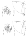
- In a retractable wiper device of this kind, there has been proposed in the prior art a wiper device (as disclosed in Japanese Utility Model Laid-Open No. 59-190648), as shown in Figs. 12 to 14.
- Specifically, in these Figures:
reference numeral 1 designates the output shaft of a reduction gear mechanism connected to a motor; numeral 2 a first crank; numeral 3 a second crank; numeral 4 a nut for fastening theoutput shaft 1 and thefirst crank 2; numeral 5 a projecting spindle projecting from thesecond crank 3; numeral 3 a nut for supporting thesecond crank 3 on thefirst crank 2 in a rocking manner;numerals first crank 2;numerals second crank 3; numeral 9 a spindle fixed in thesecond crank 3; numeral 10 a cam fitted on thespindle 9; numeral 11 a bearing member integrated with the cam; numeral 12 a link; numeral 13 a bearing member at the side of thelink 12; numeral 14 a wiper blade;numeral 15 an arm for supporting thewiper blade 14; numeral 16 a rocking shaft for thearm 15; numeral 17 a rocking lever associated with thelink 12 and fixed to therocking shaft 16; numeral 18 a slidable stopper mounted on the second crank; numeral 19 a spring for urging thestopper 18 in a direction so as to project from thesecond crank 3; numeral 20 a guide frame accommodating thespring 19 for guiding the same when thestopper 18 moves; and numeral 21 a mounting screw for fastening theguide frame 20 to thesecond crank 3. - In an ordinary wiping operation, the
output shaft 1 of the motor is rotationally driven in a forward direction, as indicated by an arrow P in Fig. 14. If thefirst crank 2 is rotated in this direction, thesecond crank 3 associated through thelink 12 and therocking lever 17 with thewiper arm 15 is rotated on thepivot 5 in the direction opposite to the direction P relative to thefirst crank 2 by the rotational reaction until it is bent to abut against theblock edge 8 of thefirst crank 2. Simultaneously with this, thestopper 18 is introduced into therecess 7a by the urging force of thespring 19 and engaged at the bent angle. Thesecond crank 3 is rotated on theoutput shaft 1 in the direction of the arrow P while being bent with respect to thefirst crank 2, and therocking shaft 16 is reciprocated by thelink 12 and therocking lever 17 so that the wiping operation is carried out by thewiper blade 14. - The range for the
wiper blade 14 to be reciprocated with thesecond crank 3 which is bent with respect to thefirst crank 2 is between a bottom turn position A and a top turn position C. Next, when a wiper switch (not shown) is turned off, the motor is reversed by an automatic fixed-position stop mechanism (not shown) so that the wiper arm is moved from the aforementioned position, which is taken when the wiper switch (not shown) is turned off, and is stopped at the bottom turn position A of the aforementioned operation range. - Through this reversing operation, the
first crank 2 is rotated in the direction opposite to that of the arrow P. through the rotational reaction, thesecond crank 3 associated with thewiper blade 14 through thelink 12 is rotated on thepivot 5 in the direction of the arrow P relative to thefirst crank 3 until it is rotated to abut against theblock edge 7 of thefirst crank 2 and is extended. Simultaneously with this, thestopper 18 is introduced into therecess 8a by the urging force of thespring 19 to engage with the same at the extended angle. - Thus, the crank effective length when the
second crank 3 is extended linearly with respect to thefirst crank 2, i.e., the inter-axis length joining theoutput shaft 1 and thespindle 9 is larger than the inter-axis length joining theoutput shaft 1 and thespindle 9 when thesecond crank 3 is bent. As a result, as shown in Fig. 14, thewiper blade 14 in the ordinary stop position (i.e., the bottom turn position) is retracted across the operation range into its retracted position B. - In the aforementioned wiping operation and blade retracting operation, the
cam 10 fitted on thespindle 9 of thesecond crank 3 is rotated on thespindle 9 integrally with thelink 12. In the forward rotations of the wiping operation, thecam 10 pushes and suppresses thestopper 18 engaging therecess 7a and leaves thestopper 18 when it rotates backward at a small angle (about 35 degrees) after the ordinary rotation (of 180 degrees). When thesecond crank 3 is completely extended with respect to thefirst crank 2, thecam 10 pushes and suppresses thestopper 18 engaging with therecess 8a. - The retractable wiper device thus constructed is enabled by a simple mechanism to retract the wiper blade from the ordinary stop position A into the retracted position B. In the forward rotation (for the wiping operation) of the motor, however, the
cam 10 assumes a state in which it does not push thestopper 18, once its in its first rotation when the wiper device operates with thefirst crank 2 and thesecond crank 3 being bent at a desired angle. In this state, the binding force for inserting thestopper 18 into therecess 7a of theblock edge 7 depends absolutely upon the pushing force of thespring 19 so that it is in an unstable state causing clattering or squeaking. Slight shocks are thereby caused at the leading end of thewiper blade 14 giving an unstable feel to the driver. - Therefore, I have proposed an improvement in which the
aforementioned cam 10 is made to have a structure of two overlapping sheets so as to maintain the bent state of the first andsecond cranks stopper 18 is fitted in the engagement recess 7a, while thefirst crank 2 is rotationally driven in the forward direction (as disclosed in Japanese Patent Laid-Open No. 61 - 244639). -
Cam members aforementioned cam 10 and are individually formed with tworecesses cam member 30 to be fixed on the aforementioned bearing member 11 is formed with a concentric,arcuate groove 30c which extends from the surface and to the back and has a play angle of 60 degrees, for example. The other cam member 341 is equipped with apin 31c to be fitted in thatarcuate groove 30c. As a result, during the forward rotations of thefirst crank 2, the arcuate face of theupper cam member 30 excepting theaforementioned recesses stopper 18 even if therecess 31a of thelower cam member 31 comes to a position to face thestopper 18. Thus, thisstopper 18 is pushed and fixed in the engagement recess 7a so that the first and second cranks are kept in their bent states. - I have also proposed another improvement in the retractable wiper device of this kind (as disclosed in Japanese Patent Laid-Open No. 62 - 299452).
- This proposal is intended to eliminate the drawback in the procedure for which the
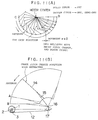
wiper blade 14 is operated from the retracted position B to ordinary rotation by the forward drive of the motor. Specifically, in the course of the relation between thefirst crank 2 and thesecond crank 3 to change from the linearly extended position to the bent position, theaforementioned stopper 18 comes out of therecess 8a toward the cam side. If, at this time, an external force such as an intense wind is exerted upon the wiper while the vehicle is running at a high speed, the wiper is forced upward in its rotating direction so that thecam member 30 relating to thelink 12 and the rockinglever 17 is rotationally accelerated in the forward direction in addition to its ordinary rotations. Considering this acceleration, the above-specified proposal forms arelief space 36 so that thestopper 18 may be inclined around the side of thefirst crank 2 in the forward direction of thesecond crank 3, as shown in Fig. 16. Moreover, thespring 19 is arranged to keep theaforementioned stopper 18 in a predetermined position at all times. In case, with this structure, theaforementioned cam member 30 is rotationally accelerated in the forward direction, saidstopper 18 is inclined into therelief space 36 against the elastic force of thespring 19. Then, the arcuate face at the outside of the cam comes into smooth contact with the trailing end face of thestopper 18 to prevent thecam member 30 and the stopper 18 from collision or hooking onto each other. As a result, the aforementionedsecond crank 3 continues its bending motion in this state until thestopper 18 comes to a position facing therecess 7a. According to the proposal thus far described, it is possible to effectively avoid both breakage which might otherwise be caused by the collision or hooking of the members and the state in which thefirst crank 2 and thesecond crank 3 might otherwise be brought to a predetermined bent angle. - The
cam members recesses cam member 30 is formed with the concentric,arcuate groove 30b having a play angle of about 180 degrees, and theother cam member 31 is formed with thebulge 31b to be fitted in thearcuate groove 30b. - In any of the proposals thus far described, while the motor is rotating backward, the extending and con tracting behaviors of the crank arm are changed in accordance with the state of the wind screen (or the front glass) because the crank arm is extended and contracted by the load of the wiper (i.e., the load for the blade to wipe off the glass). This phenomena will be described with reference to Figs. 10 and 11.
- Fig. 10 shows the operations where the blade is retracted from the top turn position C into the retracted position B by the backward drive of the motor. The wind screen is wet in the state shown at (A) in Fig. 10 and is dry or semi-dry in the state shown at (B) in Fig. 10.
- With the wind screen being dry or semi-dry, as shown by broken lines in Fig. 11, the crank arm has its pitch changed from its bent state to its extended state, when in its retracting operation. As a result, the wiper blade has its speed dropped around the central portion of its wiping pattern so that the speed is increased to complete the retraction after the crank arm is extended. Thus, the operation feel is so bad as to raise an eyesore to the driver. Because of the aforementioned movements of the wiper blade, streaks of water droplets are left due to the change in the wiping speed of the blade, thus raising a problem of obstructing the field of vision of the driver.
- With the wind screen being wet, on the other hand, the motions of the blade being retracted are smoother than those in the wet state. However, because of the low load, the shifts of the first and
second cranks - It is, therefore, an object of the present invention to provide a retractable wiper device which improves the operation feeling drastically irrespective of the state of the wind screen by making the wind blade retracting movements constant and smooth.
- According to the present invention, there is provided a retractable wiper device which comprises:
a first crank connected to the reduction output shaft of a motor;
a second crank rotatably supported on said first crank so that it is kept in association with said first crank at a predetermined bent angle, when said first crank is in a forward rotated state, and generally in a linear shape with respect to said first crank when the same is in a backward rotated state;
a stopper slidably supported by said second crank such that it is inserted into a recess formed in said first crank, when said first and second cranks reach the bent angular position or the linear angular position, to keep said second crank in each of said angular positions;
a link rotatably connected to said second crank to transmit the motions of said second crank to said wiper blade;
a first cam member rotatably secured to the connected end portion of said link to said second crank for suppressing and releasing said stopper upon said recess in accordance with its rotational position; and
a second cam member rotatably associated at a predetermined play angle with said first cam member for suppressing and releasing said stopper in a phase different from that of said first cam member and for suppressing said stopper in association with said first cam member when said first crank is in its forward rotated state,
wherein the improvement resides:
in that said first and second cam member are so shaped that they are set in the suppression release position of said stopper in the vicinity of the top turn position of said wiper blade when said first crank is in its backward rotated state;
in that a relief portion is formed to relieve the end portions of said stopper at the sides abutting against said first and second cam members in the forward direction of said first crank; and
in that said first and second cranks are set generally linear in the vicinity of the top turn position of said wiper blade when said first crank is in its backward rotated state. - The present invention has its first structural feature structure in the cam shape of first and second cam members and its second structural feature in the stopper relief portion.
- Here, the stopper relief portion according to the second structural feature is identical to that of the preceding proposal (as disclosed in Japanese Patent Laid-Open 62 - 299452). Thanks to the interactions of the two structural features, however, the following operations can be realized by adding the first structural feature to the second structural feature.
- Specifically, when in the backward rotations of the first crank, both the first and second cam members are set in the suppression release position of the stopper in the vicinity of the top turn position of the wiper blade. As a result, the first and second cranks can be released from their bent states in the vicinity of the top turn position of the wiper blade and shifted to the extended states.
- If, in this state, the first crank is uninterruptedly rotated backwards, the stopper is moved to the relief portion thanks to the second structural feature of the present invention because the stopper is released from the suppression state. As a result, no breakage is caused due to the collision or hooking onto of the members so that the abrupt crank pitch change in the vicinity of the top turn position, i.e., the shift to the extended states of the first and second cranks can be smoothly executed. Moreover, the crank pitch in that position can be promptly changed by the inertia or static frictional force at the turn of the arm or blade even if the wind screen is wet. In the dry or semi-dry state, the abrupt pitch change can likewise be secure by the frictional resistance. Thus, in the vicinity of the top turn position, the shift to the extended states of the first and second cranks can be completed without fail irrespective of the state of the wind screen.
- At the time of the abrupt crank pitch change, the backward rotating force of the first crank is hardly transmitted to the second crank. As a result, the wiper arm has its movement stopped once in the vicinity of its top turn position. Since, however, the movement stop position is in the vicinity of the turn position, the movements establish no abnormal feel and are not stopped unlike the prior art in the vicinity of the center of the wiping pattern of the wiper blade so that an excellent operation feel can be attained. Moreover, the problem of leaving the wipe partially due to the stop of the blade in the vicinity of the turn position can be solved. Since no speed changes in the switching operation from the bent states to the extended states, it is possible to prevent the water splashes and the sliding sounds, which might otherwise accompany the blade retraction.
- Other objects, features and advantages of the present invention will be described in the following with reference to the accompanying drawings, in which:
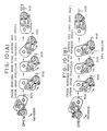
- Fig. 1 presents at (A) to (L) schematic diagrams for explaining the individual operations of an embodiment when a wiper blade is to be retracted;
- Fig. 2 is a top plan view for explaining the connected state of first and second cranks;
- Fig. 3 is a section taken along line A - B - C - D of Fig. 2;
- Fig. 4 is an exploded perspective view showing the first and second cranks;
- Fig. 5 presents at (A) and (B) a top plan view and a section showing a first cam member;
- Fig. 6 presents at (A) and (B) a top plan view and a righthand side elevation showing a second cam member;
- Fig. 7 presents at (A) to (C) schematic diagrams for explaining the individual structures of a bendable stopper;
- Fig. 8 presents at (a) and (b) schematic diagrams for explaining the loci of a wiper arm when the wiper blade is to be retracted;
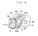
- Fig. 9 is a schematic diagram for explaining the bending operations of a stopper;
- Fig. 10 presents at (A) and (B) schematic diagrams for explaining the motions of the crank of the prior art when the wind screen is wet and dry, respectively;
- Fig. 11 presents at (a) and (b) schematic diagrams for explaining the crank loci, when in the re tracting operations, of the retractable wiper device of the prior art;
- Fig. 12 is a schematic section showing an essential portion of the retractable wiper device of the prior art;
- Fig. 13 is a top plan view of the same;
- Fig. 14 is an explanatory diagram showing the operating state of the same;
- Fig. 15 presents at (A) to (C) schematic diagrams for explaining the structure of the two cams of the prior art;
- Fig. 16 is a schematic diagram for explaining the structure in which the stopper is relieved in the retractable wiper device of the prior art;
- Fig. 17 presents at (A) to (C) schematic diagrams for explaining the structure of two cam members adopted in the structure shown in Fig. 16; and
- Fig. 18 is a schematic diagram for explaining the drawbacks in case the stopper is not bent.
- The present invention will be described in the following in connection with one embodiment thereof with reference to the accompanying drawings.
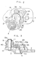
- In Figs. 2 to 4, the same or similar parts of those of the aforementioned retractable wiper device according to the prior art are designated at common reference characters. Specifically, a
first crank 2 is fixedly connected to a motorreduction output shaft 1 by means of anut 4. Asecond crank 3 is rotatably connected to the first crank 2 through asleeve 6a by means of a projectingpivot 5 which in turn is integrally fixed to thesecond crank 3. Anarcuate block member 33 is fixed to the first crank 2 and is formed withengagement recesses spindle 9 is fixed in thesecond crank 3. A cam is composed of first and second two-stackedcam members spindle 9. The upperfirst cam member 40 is formed integrally with a bearing member 11 which is fitted on thespindle 9. This bearing member 11 is connected to a linkside bearing member 13 by a connecting pin 11a projecting from the surface thereof and is prevented from coming out by asnap ring 13b while being allowed to rotate on thespindle 9 integrally with alink 12. Awiper blade 14 is connected to one end of awiper arm 15. The other end is fixed together with one end of a rockinglever 17 to a rockingshaft 16. The other end of the rockinglever 17 is fixedly connected to thelink 12. The aforementionedarcuate block member 33 is fitted at its twoends 33a on twopins 32 anchored to the first crank 2 and is fixed at its generally central portion by ascrew 34. Thesecond crank 3 has its extension and bent angle regulated in such an angular position that the leading projection 3a of the second crank 3 abuts against the twoends 33a of theblock member 33. Thisblock member 33 is formed with theaforementioned recesses stopper 42 in the extended and bent angle positions. - To the second crank 3, there is attached by a screw 21 a
guide frame 20 which is formed with a bulge facing the arcuate recess of theblock member 33. Theguide frame 20 is formed with aguide groove 35 for guiding thestopper 42 internally. Thisguide groove 35 is formed with afirst relief space 36 which is expanded as a relief around theblock member 33 in the forward direction of thesecond crank 3. Thestopper 42 is always urged by aspring 19 in the reverse direction of the second crank 3 from therelief space 36. - Next, the structures of the aforementioned first and
second cam members - The
first cam member 40 is formed integrally with the aforementioned bearing member 11, as shown in Fig. 5(B), and is positioned below the bearing member 11. Thisfirst cam member 40 is formed in its lower face with a concentric,arcuate groove 40c over an angular aperture of ϑ₁. Thecam member 40 is further formed in its lower face with arecess 40a having an angular aperture of ϑ₃ at an angular position of ϑ₂ with respect to the center line a bisecting the angular aperture of thatarcuate groove 40c. Thefirst cam member 40 is further formed in its lower face with arecess 40b which is cut at an angular position of ϑ₄ over an angular aperture of ϑ₅ at the opposite side of therecess 40a with respect to the center line a. - The aforementioned
second cam member 41 is formed with aprojection 41c projecting from the side facing thefirst cam member 40, as shown in Fig. 6. Theprojection 41c thus formed is loosely fitted in the concentric,arcuate groove 40c of thefirst cam member 40. Thesecond cam member 41 is further formed withrecesses projection 41c with respect to the center line. - In the present embodiment, the
aforementioned stopper 42 is composed of afirst stopper 42a and asecond stopper 42b, as shown in Fig. 7. These twostoppers pin 42c which is inserted in their intermediate positions go as to rotate only in one direction. In case, an external force F is exerted upon thesecond stopper 42b, as shown in (A) in Fig. 7, thesecond stopper 42b rotates on thepin 42c with respect to thefirst stopper 42a, as shown in (B) in Fig. 7. The rotating direction of thissecond stopper 42b is identical to the reverse direction of thefirst crank 2, as shown in Fig. 9. In order to ensure this rotation, theguide frame 20 is formed with asecond relief space 37. Since, thespring 19 for holding thestopper 42 in position is mounted between oneend face 42d of thesecond stopper 42b and theguide frame 20, the first and second stoppers restore their original positions when the external force F is not applied. - Next, the operation of the retractable wiper device thus constructed will be described in the following.
- Like the structures disclosed in Japanese Patent Laid-Open Nos. 61 - 244639 and 62 - 299452, the
aforementioned stopper 42 of the present wiper device can also be suppressed in its abutment state at all times, no matter what angular position the cam might take, by associating the aforementioned twocam members bulge 41c of thesecond cam member 41 fitted in the concentric,arcuate groove 40c of thefirst cam member 40 moves relatively from the leading to the trailing ends of thearcuate groove 40c. Here, a phase discrepancy is established between therecesses first cam member 40 and therecesses second cam member 41 so that the outer circumferential envelope of the two provides a completely round cam (as shown at (A) in Fig. 1, for example). Thus, the locking action or the suppressing action of thestopper 42 is maintained. - Since the first and
second cam members output shaft 1 are continued while keeping suppression upon theaforementioned stopper 42 such that thewiper blade 14 repeats its rocking motions between the top and bottom turn positions C and A of its wiping operations. - Next, the operation of the device of the present embodiment for retracting the
wiper blade 14 into the retracted position B will be described. - When the
wiper blade 14 is in the retracted position B, the wiper switch is turned OFF. Here, the wiper motor has built therein an automatic fixed-position stopping mechanism (not shown) and a circuit (not shown) for a motor reversing mechanism. By the action of this circuit, the motor is continuously driven in the forward direction. However, the reverse rotation of the motor is not started before thewiper blade 14 has returned to the top turn position C. - Fig. 1 shows at (A) and (B) the state in which the
wiper blade 14 is returned to the top turn position C. From this state, the motor is rotated backward to rotate theoutput shaft 1 in the backward direction. Fig. 1 shows at (C) and (D) the state immediately after the reverse of the motor. In this state, thefirst cam member 40 is opened to have its pitch started to change with respect to thesecond cam member 41 until therecesses cam members stopper 42. Since, however, the leading end of the stopper does not completely come out of therecess 7a, the bent states of the first andsecond cranks wiper blade 14 moves toward its bottom turn position A. - When the
recesses second cam members stopper 42, as shown at (E) and (F) in Fig. 1, the leading end of thestopper 42 comes completely out of therecess 7a. In other words, the engagement of thestopper 42 with thecam members second cranks - As a result, a force, as indicated at an arrow K, is exerted upon the
link 12 by the friction between the wiper blade and the glass surface, and thefirst crank 2 is reversed by the backward rotation of the motor. Then, the shift of the first andsecond cranks first crank 2 is driven backward, the leading end of thestopper 42 comes out of therecess 7a into therecess 8a, as shown at (G) and (H) in Fig. 1. On the other hand, the other end of thestopper 42 moves to thefirst relief space 36 while avoiding any collision or hooking onto with the first andsecond cam members stopper 42 by the first andsecond cam members wiper blade 14. At the same time, the first andsecond cranks stopper 42 into thefirst relief space 36. In the state near the top reverse position C of thewiper blade 14, the crank pitch is greatly changed by the inertia immediately after the turn of thewiper blade 14 even if the wind screen is wet. In the dry or semi-dry state, too, the large pitch change is retained by the frictional resistance. As a result, the shifts of the first andsecond cranks - During the shifts of the first and
second cranks first crank 2 is not transmitted to thewiper blade 14 so that thewiper blade 14 has its motions stopped in the vicinity of the top turn position C. Since, however, the motion stop position of thewiper blade 14 is near the top reverse position C, the stop state is felt as an extension of the turn so that the motion does not present an abnormality but can improve the operational feel dramatically. - When the leading end of the
stopper 42 reaches therecess 8a, as shown at (I) and (J) in Fig. 1, the round peripheral surface of thefirst cam member 40 presses one end of thestopper 42 so that the leading end of thestopper 42 is inserted into theaforementioned recess 8a. At the same time, thestopper 42 is returned from therelief space 36 to its original position by the urging force of thespring 19 so that its suppressed state is kept. After this, thefirst crank 2 continues the backward drive so that the first andsecond cranks wiper blade 14 to its retracted position B. - Fig. 1 shows at (K) and (L) the state in which the
wiper blade 14 reaches its retracted position B. Then, the automatic fixed-position stop mechanism operates to stop the backward drive of the motor. At this time, moreover, the first andsecond cam members recesses stopper 42 is released at the time when thewiper blade 14 reaches its retracted position B. - According to the retractable wiper device embodiment, the operation of relieving the
stopper 42 into thefirst relief space 36 against the urging force of the spring can be carried out not only upon the retraction of the wiper blade 14 (i.e., the backward rotation of the first crank 2) but also upon the wiping action by the wiper blade 14 (i.e, the forward rotation of the first crank 2). The following effects can be achieved by relieving thestopper 42 at the time of the forward rotation of thefirst crank 2. In the course from the retracted position B to the normal rotation, for example, an external force such as an intense wind may be exerted upon thewiper blade 14, while the vehicle is running at a high speed, forcing thewiper blade 14 upward or in its rotating direction. In this case, thefirst cam member 40 associated with thelink 12 and the rockinglever 17 is rotationally accelerated in the forward direction in addition to its ordinary rotation. If thestopper 42 is then inclined with respect to thefirst relief space 36, thefirst cam member 40 and thestopper 42 can be prevented from any collision or hooking onto to reduce the breakage of their parts. In the device of the present embodiment, too, there can be attained effects similar to those of the structure disclosed in Japa nese Patent Laid-Open No. 62 - 299452. - Next, the operation of a structure, in which the
aforementioned stopper 42 is made bendable, will be described. - The
recesses second cam members recesses cam members wiper blade 14 being retracted, i.e., in the state immediately after thewiper blade 14 has been turned at the top turn position C, no surplus is left in the angular apertures of therecesses second cam members second stopper 42b is bent in the backward drive direction of the first crank 2 with respect to thefirst stopper 42a, as shown in Fig. 9, and is moved into thesecond relief space 37. Thus, the aforementioned locking phenomena or the breakage of the parts can be avoided. - Incidentally, after the locking phenomena has been avoided, the
second stopper 42b is returned to its original state by the urging force of thespring 19. - Although the present invention has been described in connection with its one embodiment, it should not be limited to the embodiment but can be modified in various manners within the scope of its gist.
- For example, the positions for forming the individual recesses of the first and
second cam members second cam members stopper 42 in the vicinity of the top turn position C of thewiper blade 14 while thefirst crank 2 is rotating backward. - As has been described hereinbefore, according to the present invention, the cam for suppressing and releasing the stopper for holding the first and second cranks in the predetermined angular states is constructed of two cam members. Thus, in the forward rotation of the first crank, these two cam members are associated to keep the stopper in the suppressed state at all times. In the backward rotation of the first crank, on the other hand, when the wiper blade is to be retracted into the retracted position, the settings of the first and second cranks generally in the extended positions can be completed in the vicinity of the top turn position of the wiper blade irrespective of the state of the wind screen. In an intermediate position between the top and bottom turn positions, when the wiper blade is to be retracted, the wiper blade can be prevented from moving to have its wiping speed fluctuating. Thus, it is possible to improve the operation feel drastically and to prevent water droplets from being left in streaks on the glass surface due to a change in the wiping speed.
- The features disclosed in the foregoing description, in the claims and/or in the accompanying drawings may, both separately and in any combination thereof, be material for realising the invention in diverse forms thereof.
Claims (17)
a first crank connected to the reduction output shaft of a motor so that it may be rotated forward and backward;
a second crank rotatably supported to said first crank so that it may come into a first state, in which it is bent at a predetermined angle with respect to said first crank, while said first crank is being rotated forward, and into a second state, in which it is generally linear with respect to said first crank, while said first crank is being rotated backward;
a stopper member supported movably by said second crank so that it may be pushed into engagement with said first crank, when said second crank is brought into said first or second state, to keep said second crank in said first or second state;
a cam including: a first cam member rotatably supported to said second crank and secured to a link for transmitting the action of said second crank to a wiper blade, said first cam member having a first face for pushing said stopper member into engagement with said first crank and a second face for releasing the engagement of said stopper member with said first crank; and a second cam member borne in said second crank coaxially with said first cam member and connected to said first cam member at a predetermined play angle, said second cam member having a third face for pushing said stopper member into engagement with said first crank and a fourth face for releasing the engagement of said stopper member with said first crank, said cam being shaped such that said first face and said third face keep said stopper member engaging with said first crank in a pushed state at all times when said first crank is in its forward rotated state and such that said second face and said fourth face are overlapped in the vicinity of the top turn position of said wiper blade, when said first crank is in its backward rotated state, to release the engagement of said stopper member with said first crank; and
a first relief portion for relieving the end portion of said stopper member at the side of said cam in the forward direction of said first crank when said first crank is in its backward rotated state,
whereby said first crank and said second crank are generally linear through said first relief portion in the vicinity of the top turn position of said wiper blade when said first crank is in its backward rotated state.
a first crank connected to the reduction output shaft of a motor so that it may be rotated forward and backward;
a second crank borne in said first crank so that it may come into a first state, in which it is bent at a predetermined angle with respect to said first crank, while said first crank is being rotated forward, and into a second state, in which it is generally linear with respect to said first crank, while said first crank is being rotated backward;
first and second recesses formed in said first crank are such that they correspond to said first and second states of said second crank;
a stopper member movably supported on said second crank for being pushed into said recess, when said second crank is brought into said first state, to keep said second crank in said first state and into said second recess, when said second crank is brought into said second state, to keep said second crank in said second state;
cam means including: a first cam member rotatably supported to said second crank and connected to a link for transmitting the action of said second crank to a wiper blade, said first cam member having a first face for pushing said stopper member and a second face for allowing said stopper member to come out of said first recess or said second recess; and a second cam member rotatably supported to said second crank coaxially with said first cam member and connected to said first cam member at a predetermined play angle, said second cam member having a third face for pushing said stopper member and a fourth face for allowing said stopper member to come out of said first recess or said second recess, the relationship of said first face, said second face, said third face and said fourth face being set such that the first face of said first cam member and the third face of said second cam member keep said stopper member in the pushed state at all times, when said first crank is in its forward rotated state, and such that said second face and said fourth face are overlapped in the vicinity of the top turn position of said wiper blade, when said first crank is in its backward rotated state, to allow said stopper member to come out of said first recess; and
a first relief portion for allowing the end portions of said stopper member at the sides of said first cam member and said second cam member to be relieved in the forward direction of said first crank when said first crank is in its backward rotated state,
whereby said first crank and said second crank are generally linear in the vicinity of the top turn position of said wiper blade through said first relief portion when said first crank is in its backward rotated state.
a first crank connected to the reduction output shaft of a motor;
a second crank rotatably supported on said first crank so that it is kept in association with said first crank at a predetermined bent angle, when said first crank is in its forward rotated state, and generally in a linear shape with respect to said first crank when the same is in its backward rotated state;
a stopper slidably supported by said second crank such that it is inserted into a recess formed in said first crank, when said first and second cranks reach the bent angular position or the linear angular position, to keep said second crank in each of said angular positions;
a link rotatably connected to said second crank to transmit the motions of said second crank to said wiper blade;
a first cam member rotatably secured to the connected end portion of said link to said second crank to suppress and release said stopper upon said recess in accordance with its rotational position; and
a second cam member rotatably associated at a predetermined play angle with said first cam member for suppressing and releasing said stopper in a phase different from that of said first cam member and for suppressing said stopper in association with said first cam member when said first crank is in its forward rotated state,
wherein the improvement resides:
in that said first and second cam members are so shaped that they are set in the suppression release position of said stopper in the vicinity of the top turn position of said wiper blade when said first crank is in its backward rotated state;
in that a relief portion is formed to relieve the end portions of said stopper at the sides abutting against said first and second cam members in the forward direction of said first crank; and
in that said first and second cranks are set generally linear in the vicinity of the top turn position of said wiper blade when said first crank is in its backward rotated state.
Applications Claiming Priority (2)
| Application Number | Priority Date | Filing Date | Title |
|---|---|---|---|
| JP168905/89 | 1989-06-30 | ||
| JP1168905A JPH0332963A (en) | 1989-06-30 | 1989-06-30 | Storage type wiper device |
Publications (3)
| Publication Number | Publication Date |
|---|---|
| EP0405535A2 true EP0405535A2 (en) | 1991-01-02 |
| EP0405535A3 EP0405535A3 (en) | 1992-01-22 |
| EP0405535B1 EP0405535B1 (en) | 1995-08-16 |
Family
ID=15876737
Family Applications (1)
| Application Number | Title | Priority Date | Filing Date |
|---|---|---|---|
| EP90112315A Expired - Lifetime EP0405535B1 (en) | 1989-06-30 | 1990-06-27 | Retractable wiper device |
Country Status (4)
| Country | Link |
|---|---|
| US (1) | US5168594A (en) |
| EP (1) | EP0405535B1 (en) |
| JP (1) | JPH0332963A (en) |
| DE (1) | DE69021652T2 (en) |
Cited By (1)
| Publication number | Priority date | Publication date | Assignee | Title |
|---|---|---|---|---|
| GB2307534A (en) * | 1995-11-27 | 1997-05-28 | Ford Motor Co | A windscreen wiper mechanism with locking means and depressed parking position |
Families Citing this family (1)
| Publication number | Priority date | Publication date | Assignee | Title |
|---|---|---|---|---|
| DE19735818C2 (en) * | 1997-08-18 | 1999-10-21 | Daimler Chrysler Ag | Fastening device for a windshield wiper system of a motor vehicle |
Citations (3)
| Publication number | Priority date | Publication date | Assignee | Title |
|---|---|---|---|---|
| EP0200119A2 (en) * | 1985-04-20 | 1986-11-05 | Asmo Co., Ltd. | Retractable type wiper apparatus |
| FR2583491A1 (en) * | 1985-06-12 | 1986-12-19 | Marchal Equip Auto | Transmission mechanism, in particular for windscreen wiper, and windscreen wiper device equipped with such a mechanism |
| GB2191681A (en) * | 1986-06-18 | 1987-12-23 | Asmo Co Ltd | Windscreen wiper drive transmission mechanism |
Family Cites Families (13)
| Publication number | Priority date | Publication date | Assignee | Title |
|---|---|---|---|---|
| US2753721A (en) * | 1953-10-05 | 1956-07-10 | Redmond Company Inc | Direction-sensitive linkage-lengthening arrangement, particularly for use in depressed parking of windshield wipers |
| GB978840A (en) * | 1962-10-09 | 1964-12-23 | Gen Motors Ltd | Windscreen wiper drive mechanisms |
| US3665772A (en) * | 1970-09-11 | 1972-05-30 | Ford Motor Co | Windshield wiper motor link depressed park mechanism |
| US3699605A (en) * | 1971-06-18 | 1972-10-24 | Gen Motors Corp | Depressed park windshield wiper |
| JPS57118957A (en) * | 1981-01-14 | 1982-07-24 | Nissan Motor Co Ltd | Wiper unit with rise-up mechanism |
| JPS57164843A (en) * | 1981-03-31 | 1982-10-09 | Nippon Denso Co Ltd | Driving device of window wiper |
| JPS59190648A (en) * | 1983-04-13 | 1984-10-29 | Hitachi Ltd | Reference electrode for high temperature |
| GB2138674B (en) * | 1983-04-28 | 1986-06-25 | Rolls Royce Motors Ltd | A transmission mechanism |
| FR2581945B1 (en) * | 1985-04-01 | 1987-08-07 | Marchal Equip Auto | TRANSMISSION MECHANISM, PARTICULARLY FOR WINDSCREEN WIPERS, AND WIPER DEVICE PROVIDED WITH SUCH A MECHANISM |
| JPS6345988A (en) * | 1986-04-09 | 1988-02-26 | Hitachi Ltd | Circuit for separating luminance signal and chrominance signal |
| JPS62299452A (en) * | 1986-06-18 | 1987-12-26 | Asmo Co Ltd | Retractable type wiper device |
| FR2630068B1 (en) * | 1988-04-13 | 1990-08-24 | Valeo Systemes Dessuyage | DEVICE FOR DRIVING A WINDSCREEN WIPER BLADE |
| US4924726A (en) * | 1989-06-05 | 1990-05-15 | General Motors Corporation | Reverse to park mechanism with secure latching |
-
1989
- 1989-06-30 JP JP1168905A patent/JPH0332963A/en active Pending
-
1990
- 1990-06-27 EP EP90112315A patent/EP0405535B1/en not_active Expired - Lifetime
- 1990-06-27 DE DE69021652T patent/DE69021652T2/en not_active Expired - Fee Related
- 1990-06-29 US US07/545,700 patent/US5168594A/en not_active Expired - Fee Related
Patent Citations (3)
| Publication number | Priority date | Publication date | Assignee | Title |
|---|---|---|---|---|
| EP0200119A2 (en) * | 1985-04-20 | 1986-11-05 | Asmo Co., Ltd. | Retractable type wiper apparatus |
| FR2583491A1 (en) * | 1985-06-12 | 1986-12-19 | Marchal Equip Auto | Transmission mechanism, in particular for windscreen wiper, and windscreen wiper device equipped with such a mechanism |
| GB2191681A (en) * | 1986-06-18 | 1987-12-23 | Asmo Co Ltd | Windscreen wiper drive transmission mechanism |
Cited By (3)
| Publication number | Priority date | Publication date | Assignee | Title |
|---|---|---|---|---|
| GB2307534A (en) * | 1995-11-27 | 1997-05-28 | Ford Motor Co | A windscreen wiper mechanism with locking means and depressed parking position |
| US5826294A (en) * | 1995-11-27 | 1998-10-27 | Ford Motor Company | Compact depressed park wiper system with clutch lock mechanism |
| GB2307534B (en) * | 1995-11-27 | 2000-03-08 | Ford Motor Co | A wiper system with clutch lock mechanism |
Also Published As
| Publication number | Publication date |
|---|---|
| US5168594A (en) | 1992-12-08 |
| EP0405535A3 (en) | 1992-01-22 |
| EP0405535B1 (en) | 1995-08-16 |
| DE69021652D1 (en) | 1995-09-21 |
| JPH0332963A (en) | 1991-02-13 |
| DE69021652T2 (en) | 1996-01-18 |
Similar Documents
| Publication | Publication Date | Title |
|---|---|---|
| CN1152515A (en) | Belt stretching device with pre-drawing and force-limiting device | |
| US6488134B2 (en) | Step-by-step ratchet mechanism with a silent ratchet | |
| JP5907555B2 (en) | Parking brake device for transmission | |
| JPH03284446A (en) | Wiper device | |
| JP2719608B2 (en) | Wiper | |
| EP0405535A2 (en) | Retractable wiper device | |
| EP0200119B1 (en) | Retractable type wiper apparatus | |
| WO1995001893A1 (en) | Depressed park windshield wiper mechanism | |
| US4729144A (en) | Retractable type wiper apparatus | |
| US4294553A (en) | Ribbon feed mechanism | |
| JP2521166B2 (en) | Wiping range switching device for wiper | |
| JP3258139B2 (en) | Automatic transmission parking mechanism | |
| JP2836119B2 (en) | Wiper | |
| KR19980063737A (en) | Actuator for Automatic Transmission | |
| JP2836120B2 (en) | Wiper | |
| JPS62299452A (en) | Retractable type wiper device | |
| US6007040A (en) | Seat slide apparatus | |
| JP2507892Y2 (en) | Intermittent rotation transmission device | |
| JP4467993B2 (en) | Shift control device for manual transmission | |
| JP2587056B2 (en) | Retractable wiper device | |
| JP2849427B2 (en) | Wiping range switching device for wiper | |
| KR910004262Y1 (en) | Parking apparatus of automatic transmission | |
| JP2762597B2 (en) | Wiper device | |
| JPH03118257A (en) | Wiper | |
| JPH03118260A (en) | Wiper |
Legal Events
| Date | Code | Title | Description |
|---|---|---|---|
| PUAI | Public reference made under article 153(3) epc to a published international application that has entered the european phase |
Free format text: ORIGINAL CODE: 0009012 |
|
| 17P | Request for examination filed |
Effective date: 19900627 |
|
| AK | Designated contracting states |
Kind code of ref document: A2 Designated state(s): DE IT |
|
| PUAL | Search report despatched |
Free format text: ORIGINAL CODE: 0009013 |
|
| AK | Designated contracting states |
Kind code of ref document: A3 Designated state(s): DE IT |
|
| 17Q | First examination report despatched |
Effective date: 19930429 |
|
| GRAA | (expected) grant |
Free format text: ORIGINAL CODE: 0009210 |
|
| ITF | It: translation for a ep patent filed |
Owner name: PATRITO BREVETTI |
|
| AK | Designated contracting states |
Kind code of ref document: B1 Designated state(s): DE IT |
|
| REF | Corresponds to: |
Ref document number: 69021652 Country of ref document: DE Date of ref document: 19950921 |
|
| PLBE | No opposition filed within time limit |
Free format text: ORIGINAL CODE: 0009261 |
|
| STAA | Information on the status of an ep patent application or granted ep patent |
Free format text: STATUS: NO OPPOSITION FILED WITHIN TIME LIMIT |
|
| 26N | No opposition filed | ||
| PGFP | Annual fee paid to national office [announced via postgrant information from national office to epo] |
Ref country code: DE Payment date: 20000502 Year of fee payment: 10 |
|
| PG25 | Lapsed in a contracting state [announced via postgrant information from national office to epo] |
Ref country code: DE Free format text: LAPSE BECAUSE OF NON-PAYMENT OF DUE FEES Effective date: 20010403 |
|
| PG25 | Lapsed in a contracting state [announced via postgrant information from national office to epo] |
Ref country code: IT Free format text: LAPSE BECAUSE OF NON-PAYMENT OF DUE FEES;WARNING: LAPSES OF ITALIAN PATENTS WITH EFFECTIVE DATE BEFORE 2007 MAY HAVE OCCURRED AT ANY TIME BEFORE 2007. THE CORRECT EFFECTIVE DATE MAY BE DIFFERENT FROM THE ONE RECORDED. Effective date: 20050627 |