EP0200119A2 - Retractable type wiper apparatus - Google Patents
Retractable type wiper apparatus Download PDFInfo
- Publication number
- EP0200119A2 EP0200119A2 EP86105404A EP86105404A EP0200119A2 EP 0200119 A2 EP0200119 A2 EP 0200119A2 EP 86105404 A EP86105404 A EP 86105404A EP 86105404 A EP86105404 A EP 86105404A EP 0200119 A2 EP0200119 A2 EP 0200119A2
- Authority
- EP
- European Patent Office
- Prior art keywords
- crank
- cam
- detent
- cam members
- recess
- Prior art date
- Legal status (The legal status is an assumption and is not a legal conclusion. Google has not performed a legal analysis and makes no representation as to the accuracy of the status listed.)
- Granted
Links
- 239000003638 chemical reducing agent Substances 0.000 claims abstract description 6
- 238000006073 displacement reaction Methods 0.000 description 3
- 244000145845 chattering Species 0.000 description 1
- 238000006467 substitution reaction Methods 0.000 description 1
Images


Classifications
-
- B—PERFORMING OPERATIONS; TRANSPORTING
- B60—VEHICLES IN GENERAL
- B60S—SERVICING, CLEANING, REPAIRING, SUPPORTING, LIFTING, OR MANOEUVRING OF VEHICLES, NOT OTHERWISE PROVIDED FOR
- B60S1/00—Cleaning of vehicles
- B60S1/02—Cleaning windscreens, windows or optical devices
- B60S1/04—Wipers or the like, e.g. scrapers
- B60S1/06—Wipers or the like, e.g. scrapers characterised by the drive
- B60S1/16—Means for transmitting drive
- B60S1/18—Means for transmitting drive mechanically
- B60S1/185—Means for transmitting drive mechanically with means for stopping or setting the wipers at their limit of movement
-
- Y—GENERAL TAGGING OF NEW TECHNOLOGICAL DEVELOPMENTS; GENERAL TAGGING OF CROSS-SECTIONAL TECHNOLOGIES SPANNING OVER SEVERAL SECTIONS OF THE IPC; TECHNICAL SUBJECTS COVERED BY FORMER USPC CROSS-REFERENCE ART COLLECTIONS [XRACs] AND DIGESTS
- Y10—TECHNICAL SUBJECTS COVERED BY FORMER USPC
- Y10T—TECHNICAL SUBJECTS COVERED BY FORMER US CLASSIFICATION
- Y10T74/00—Machine element or mechanism
- Y10T74/18—Mechanical movements
- Y10T74/18416—Rotary to alternating rotary
- Y10T74/18456—Crank, pitman, and lever
-
- Y—GENERAL TAGGING OF NEW TECHNOLOGICAL DEVELOPMENTS; GENERAL TAGGING OF CROSS-SECTIONAL TECHNOLOGIES SPANNING OVER SEVERAL SECTIONS OF THE IPC; TECHNICAL SUBJECTS COVERED BY FORMER USPC CROSS-REFERENCE ART COLLECTIONS [XRACs] AND DIGESTS
- Y10—TECHNICAL SUBJECTS COVERED BY FORMER USPC
- Y10T—TECHNICAL SUBJECTS COVERED BY FORMER US CLASSIFICATION
- Y10T74/00—Machine element or mechanism
- Y10T74/21—Elements
- Y10T74/2173—Cranks and wrist pins
- Y10T74/2179—Adjustable
Definitions
- This invention relates to a wiper apparatus for wiping a windshield of an automobile, and more particularly to improvements on a retractable type wiper apparatus the wiper blade of which is adapted to be retracted or concealed from view when not in use.
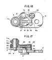
- Japanese Utility Model Application Public Disclosure No. 59-190648 discloses a typical retractable wiper apparatus of the type described, as shown in Figs. 20 to 22 attached to the present application.
- the prior art wiper apparatus illustrated therein comprises a first crank 2 connected to and locked by a nut 4 to an output shaft 1 of a reducer which is in turn connected to a wiper motor, and a second crank 3 which is secured to the first crank by means of a first' pivot shaft 5 projecting from the second crank and a nut 6.
- the first crank 2 is formed with stop shoulders 7 and 8 having locking recesses 7a and 8a, respectively.
- Secured to the second crank 3 is a second pivot shaft 9 over which a cam 10 is fitted.
- a bearing 11 is also fitted over the pivot shaft 9 and secured integrally to the cam 10.
- a first link 12 is secured to the bearing 11 by means of a socket 13 which is connected to the link 12 and adapted to receive the bearing 11.
- a wiper blade 14 is supported by an arm 15 which is secured at a pivot 16 to a second link 17 which is in turn connected to the first link 12.
- a detent 18 engageable with locking recesses 7a, 8a is slidably mounted in a guide frame 20 and is biased outwardly by a spring 19.
- the frame 20 is fastened to the second crank 3 by screws 21.
- the motor output shaft 1 is rotated in the forward direction of rotation as indicated by the arrow P.
- the rotation of the first crank 2 in this direction causes the second crank 3 connected by links 12 and 17 to the wiper arm 15 to be relatively rotated about the pivot shaft 5 due to the rotational resistance of the second crank until the second crank is bent relative to the first crank and comes into abutment with the stop shoulder 8 of the first crank 2, whereupon the detent 18 is urged into the recess 7a to lock the second crank to the first crank at said bent-angle.
- the second crank 3 While angled relative to the first crank 2 as shown in Fig. 22, the second crank 3 is thus rotated about the output shaft 1 in the direction P, whereby the pivot pin 16 is moved in its reciprocal rotating motion by means of the links 12, 17 to operate the wiper blade 14 for wiping action.
- the range in which the wiper blade is reciprocally moved with the second crank 3 angled relative to the first crank 2 is a normal range of operation.
- the wiper blade is stopped at the extreme end A of the range of operation by an automatic stopping - at - fixed position mechanism (not shown).
- the wiper motor When it is desired to stow away or retract the wiper arm from its normal stop position, the wiper motor is driven in the reverse direction, so that the first crank 2 is rotated in a direction opposite from that indicated by the arrow P.
- the second crank 3 which is connected to the wiper blade by means of the links is caused to relatively rotate about the pivot shaft 5 due to the rotational resistance until the crank 3 comes into abutment with the stop shoulder 7 of the first crank 2 to assume the straight extended position whereupon the detent 17 is urged into the recess 8a to lock the second crank at its extended position.
- the cam 10 fitted over the pivot shaft 9 of the second crank 3 is rotated in unison with the link 12.
- the cam 10 is adapted to press and lock the detent 18 which is in engagement with the recess 7a during the forward rotation for the wiping operation and to disengage from the detent upon reverse - rotation through some degrees of angle (about 35°) after the normal rotation (180°) and press and lock the detent 18 as it is engaged with the recess 8a when the second crank 3 is completely extended relative to the first crank.
- the present invention provides a retractable type wiper apparatus comprising a first crank connected to an output shaft of a reducer of a wiper motor; a second crank rotatably secured to the first crank by means of a first pivot shaft and so arranged that the second crank is kept bent at a predetermined angle relative to the first crank during the rotation of the first crank in the forward direction, and kept extended substantially straight relative to the first crank during the rotation of the first crank in the reverse direction; a detent slidably mounted in the second crank and adapted to be resiliently urged into a first recess and a second recess in the first crank to thereby lock the second crank in place when the second crank is positioned at the predetermined angled and at the straight extended position, respectively relative to the first crank; link means rotatably connected to the second crank by means of a second pivot shaft for transmitting the motion of the second crank to a wiper blade; and cam means rotatably mounted over the second pivot shaft and adapted to press and lock said detent as it is urged into
- the cam means for pressing and locking the detent in place comprises two cam members cooperating to always maintain the detent in its pressed and locked position during the rotation of the output shaft of the reducer in the forward direction (wiping'operation) whatover angular position the cams may be at whereby there may be no chattering or creaking during the wiping operation.
- FIG. 1 to 3 components of the wiper apparatus of this invention which are similar to corresponding components of the prior art wiper apparatus described hereinabove and shown in Figs. 20 - 22 are designated by the same reference numerals as in the prior art apparatus.
- the wiper apparatus comprises a first crank 2 connected to and locked by a nut 4 to an output shaft 1 of a reducer (not shown) which is in turn connected to a wiper motor (not shown), and a second crank 3 which is secured to the first crank 2 by means of a first pivot shaft 5 projecting from the second crank and a nut 6.
- the first crank 2 is formed with stop shoulders 7 and 8 having locking recesses 7a and 8a, respectively.
- a second pivot shaft 9 over which cam means comprising two stacked cam members 30, 31 is rotatably mounted.
- a bearing 11 is integrally connected with the upper cam member 30 of the cam means and is also fitted over the pivot shaft 9.
- a first link 12 is securedly connected to the bearing 11 by means of a socket 13 adapted to receive the bearing and having slots 13a for receiving connecting pins lla projecting from the bearing to prevent relative rotational movement between the socket and bearing.
- a snap ring 13b is mounted on the shaft 9 to retain the bearing 11 in place.
- the cam members 30 and 31 are formed around its periphery with two notches 30a, 30b and 31a, 31b, respectively spaced apart from each other by a displacement angle 6 of 120° as shown in Figs. 4A - 4C and SA - 5C.
- the upper cam member 30 connected integrally with the bearing 11 is further formed with a concentric arcuate slot 30C extending through a lost-motion angle of 60°.
- the lower cam member 31 has a projection extending therefrom and adapted to be inserted into the arcuate slot 30C.
- Figs. 6A and 6B illustrate the wiper blade 14 stopped at the retracted position B wherein the second crank 3 is extended straight in axial alignment with the first crank 2.
- the notches 30a, 30b and 31a, 31b of the cam members 30 and 31, respectively are in alignment with each other, and the aligned notches 30a, 31a are in an angular position opposing the detent 18, so that the detent, released from the locking action by the cam members 30, 31, is urged into the locking recess 8a by the biasing force of the spring 19 alone.
- Figs. 7A and 7B illustrate the first crank 2 rotated through about 30° by the driving of the wiper motor in the forward direction, whereby the detent 18 is dislodged from the recess 8a and urged into the recess 7a with the second crank 3 bent at the corresponding angle relative to the first crank 2.
- Figs. 8A and 8B illustrate the first crank 2 further rotated through about 60°, whereby the cam member 30 is rotated through a corresponding angle while the projection 31C of the second cam 31 relatively moves along the arcuate slot 30C from one end to the other end thereof where there is a displacement in phase between the notches 30a, 30b of the cam member 30 and the notches 31a, 31b, whereby the two cam members cooperate to define a complete circular cam to lock the detent 18 in place.
- cam members 30 and 31 will be rotated . in unison while maintaining the detent 18 locked.
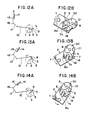
- Figs. 9A and 9B illustrate the wiper blade 14 having arrived at one extreme end C of the wiping movement, from which the wiper blade is reversed in its direction of movement.
- Figs. 10A and 10B illustrate the wiper blade being rotated in the reverse direction.
- Figs. 11A and 11B illustrate the wiper blade 14 having reached the other extreme end A of the wiping movement which is the point of reversal for the normal wiping operation.
- a switch (not shown) disposed in an electric power supply circuit (not shown) is thrown into an "off" position, said circuit having an automatic stopping - at - fixed position mechanism and a reversing mechanism for the wiper motor.
- the wiper motor is continued to be rotated in the forward direction under the control of the circuit until the wiper blade 14 is moved from the position A back to the position C whereupon the motor is reversed.
- Figs. 12A and 12B illustrate the wiper blade 14 moved back to the point of reversal C where the wiper motor is reversed to rotate the output shaft 1 in the reverse direction.
- Figs. 13A and 13B illustrate the first crank 2 rotated through about 60° by the reverse rotation of the output shaft 1.
- the notches 30a, 30b and 31a, 31b of the cam members 30 and 31, respectively are in alignment with each other, and the aligned notches 30b, 31b are in an angular position opposing the detent 18, so that the detent is released from the locking action by the cam members.
- Figs. 14A and 14B illustrate the detent 18 dislodged from the recess 7a and urged into the recess 8a while the second crank 3 is disengaged from the stop shoulder 8 and brought into abutment with the stop shoulder 7 so that the first and second cranks are straightened in longitudinal alignment.
- Figs. 15A and 15B illustrate the first and second cranks 2, 3 further rotated in the reverse direction until the wiper blade 14 has.reached the extreme end A of the normal wiping movement.
- Figs. 16A and 16B illustrate the first and second cranks 2, 3 in their straightened position continuing to rotate until the wiper blade 14 has been moved from the extreme end A of the wiping movement to the retracted position B.
- the automatic stopping - at - fixed position mechanism is actuated to stop the wiper motor.
- the wiper blade 14 is thus moved to the retracted position B by the reverse rotation of the output shaft 1, the notches 30a, 30b and 31a, 31b of the cam members 30 and 31, respectively are aligned with each other, and the aligned notches 30a, 31a are in an angular position opposing the detent 18 to release the locking action on the detent.
- the angle of displacement between the notches 30a, 31a and 30b, 31b of the cam members 30 and 31 is shown as 120°
- the angle of arc (lost motion) of the arcuate slot 30C of the cam member 30 is shown as 60°
- the bent angle between the first and second cranks 2, 3 is described as 30°, these angles may be varied depending upon the amount in which the wiper blade is to be retracted.
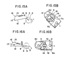
- Figs. 17 to 19 show an alternate embodiment of the wiper apparatus of this invention, in which component portions of the wiper apparatus which are similar to corresponding portions of the wiper apparatus shown in Figs. 1 - 16 are designated by the same reference numerals as in the first embodiment.
- an arcuate stop member 33 is fitted at its opposite ends over a pair of spaced apart pins upstanding from the first crank 2, in substitution for the stop shoulders 7 and 8 in the first embodiment.
- the stop member 33 is further secured by a screw 34.
- the straight extended position and the angled position that the second crank assumes relative to the first crank 2 are determined by an extension 3a of the second crank abutting against the opposite ends of the stop member 33 adjacent the pins 32.
- the arcuate stop member 33 is formed adjacent the opposite ends thereof with a pair of spaced locking recesses 7a and 8a for receiving the detent 18 at its angled and straight extended positions, respectively.
Landscapes
- Engineering & Computer Science (AREA)
- Mechanical Engineering (AREA)
- Transmission Devices (AREA)
Abstract
Description
- This invention relates to a wiper apparatus for wiping a windshield of an automobile, and more particularly to improvements on a retractable type wiper apparatus the wiper blade of which is adapted to be retracted or concealed from view when not in use.
- Japanese Utility Model Application Public Disclosure (Kohkai publication) No. 59-190648 discloses a typical retractable wiper apparatus of the type described, as shown in Figs. 20 to 22 attached to the present application.
- More specifically, the prior art wiper apparatus illustrated therein comprises a
first crank 2 connected to and locked by anut 4 to anoutput shaft 1 of a reducer which is in turn connected to a wiper motor, and asecond crank 3 which is secured to the first crank by means of a first'pivot shaft 5 projecting from the second crank and anut 6. Thefirst crank 2 is formed withstop shoulders recesses second crank 3 is asecond pivot shaft 9 over which acam 10 is fitted. Abearing 11 is also fitted over thepivot shaft 9 and secured integrally to thecam 10. Afirst link 12 is secured to thebearing 11 by means of asocket 13 which is connected to thelink 12 and adapted to receive thebearing 11. - A
wiper blade 14 is supported by anarm 15 which is secured at apivot 16 to asecond link 17 which is in turn connected to thefirst link 12. A detent 18 engageable withlocking recesses guide frame 20 and is biased outwardly by aspring 19. Theframe 20 is fastened to thesecond crank 3 byscrews 21. - During the normal wiping operation the
motor output shaft 1 is rotated in the forward direction of rotation as indicated by the arrow P. The rotation of thefirst crank 2 in this direction causes thesecond crank 3 connected bylinks wiper arm 15 to be relatively rotated about thepivot shaft 5 due to the rotational resistance of the second crank until the second crank is bent relative to the first crank and comes into abutment with thestop shoulder 8 of thefirst crank 2, whereupon thedetent 18 is urged into therecess 7a to lock the second crank to the first crank at said bent-angle. While angled relative to thefirst crank 2 as shown in Fig. 22, thesecond crank 3 is thus rotated about theoutput shaft 1 in the direction P, whereby thepivot pin 16 is moved in its reciprocal rotating motion by means of thelinks wiper blade 14 for wiping action. - The range in which the wiper blade is reciprocally moved with the
second crank 3 angled relative to thefirst crank 2 is a normal range of operation. Upon the wiper motor being deenergized, the wiper blade is stopped at the extreme end A of the range of operation by an automatic stopping - at - fixed position mechanism (not shown). - When it is desired to stow away or retract the wiper arm from its normal stop position, the wiper motor is driven in the reverse direction, so that the
first crank 2 is rotated in a direction opposite from that indicated by the arrow P. Thesecond crank 3 which is connected to the wiper blade by means of the links is caused to relatively rotate about thepivot shaft 5 due to the rotational resistance until thecrank 3 comes into abutment with thestop shoulder 7 of thefirst crank 2 to assume the straight extended position whereupon thedetent 17 is urged into therecess 8a to lock the second crank at its extended position. - The effective length of the cranks when the
second crank 3 is extended straight relative to thefirst crank 2, that is, the distance between the twoshafts shafts - During the wiping and blade retracting operations the
cam 10 fitted over thepivot shaft 9 of thesecond crank 3 is rotated in unison with thelink 12. Thecam 10 is adapted to press and lock thedetent 18 which is in engagement with therecess 7a during the forward rotation for the wiping operation and to disengage from the detent upon reverse - rotation through some degrees of angle (about 35°) after the normal rotation (180°) and press and lock thedetent 18 as it is engaged with therecess 8a when thesecond crank 3 is completely extended relative to the first crank. - While the prior art retractable wiper apparatus described above is capable of retracting the wiper blade from the normal stop position into the retracted position by means of the relatively simple mechanism, during the normal continuous driving of the motor (wiper operation) with the
second crank 3 bent at the predetermined angle relative to thefirst crank 2 such condition occurs once per rotation that thecam 10 is disengaged from pressing contact with thedetent 18. In such condition there is instability in operation in that the biasing force of thespring 19 alone is relied on for urging the detent 18 into therecess 7a of thestop shoulder 7. As a result, play or creaking tends to occur, causing clattering at the tip of the wiper blade and making the automobile driver feel uneasy. - Briefly, the present invention provides a retractable type wiper apparatus comprising a first crank connected to an output shaft of a reducer of a wiper motor; a second crank rotatably secured to the first crank by means of a first pivot shaft and so arranged that the second crank is kept bent at a predetermined angle relative to the first crank during the rotation of the first crank in the forward direction, and kept extended substantially straight relative to the first crank during the rotation of the first crank in the reverse direction; a detent slidably mounted in the second crank and adapted to be resiliently urged into a first recess and a second recess in the first crank to thereby lock the second crank in place when the second crank is positioned at the predetermined angled and at the straight extended position, respectively relative to the first crank; link means rotatably connected to the second crank by means of a second pivot shaft for transmitting the motion of the second crank to a wiper blade; and cam means rotatably mounted over the second pivot shaft and adapted to press and lock said detent as it is urged into either said first or second recess; characterized in that said cam comprises two superposed cam members both engageable with said detent, one of the cam members being connected integrally with said link means and the other of the cam members being adapted to be moved together with the one cam member with.a limited range of lost motion so that the two cam members are maintained at such angles relative to each other that they cooperate to press and lock said detent during the rotation of said first crank in the forward direction.
- Accordingly, it is an object of this invention to provide an improved retractable wiper apparatus in which the cam means for pressing and locking the detent in place comprises two cam members cooperating to always maintain the detent in its pressed and locked position during the rotation of the output shaft of the reducer in the forward direction (wiping'operation) whatover angular position the cams may be at whereby there may be no chattering or creaking during the wiping operation.
- The features and advantages of the present invention will be more fully disclosed in the following specification with reference to the accompanying drawings, in which:
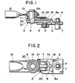
- Fig. 1 is a longitudinal cross-sectional view of the principal part of the retractable type wiper apparatus according to one embodiment of the present invention;
- Fig. 2 is a plan view of the wiper apparatus shown in Fig. 1;
- Fig. 3 is an exploded perspective view of the wiper apparatus shown in Fig. 1;
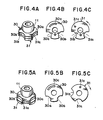
- Fig. 4A is a perspective view of the cam means according to the present invention illustrating the two cam members at the same angular position;
- Figs. 4B and 4C are plan views of the first and second cam members of the cam means shown in Fig. 4A, respectively;
- Fig. 5A is a view of the cam means similar to Fig. 4A but illustrating the cam members at different angular positions;
- Figs. 5B and 5C are plan views of the first and second cam members of the cam means shown in Fig. 5A, respectively;
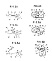
- Figs. 6A - 11A and 6B - 11B are diagrammatic views illustrating the successive steps of the wiping operation by the wiper apparatus;
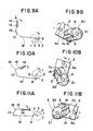
- Figs. 12A - 16A and 12B - 16B are diagrammatid views illustrating the successive steps of the retracting operation of the wiper apparatus;
- Fig. 17 is a longitudinal cross-sectional views of the principal part of the retractable type wiper apparatus according to an alternate embodiment of the invention;
- Fig. 18 is a plan view of the wiper apparatus shown in Fig. 17;
- Fig. 19 is an exploded perspective view of the wiper apparatus shown in Fig. 17;
- Fig. 20 is a longitudinal cross-sectional view of a prior art retractable type wiper apparatus;
- Fig. 21 is a plan view of the wiper apparatus shown in Fig. 12; and
- Fig. 22 is a diagrammatic view illustrating the wiper apparatus in operation.
- An embodiment of the present invention will now be described with reference to Figs. 1 to 3 in which components of the wiper apparatus of this invention which are similar to corresponding components of the prior art wiper apparatus described hereinabove and shown in Figs. 20 - 22 are designated by the same reference numerals as in the prior art apparatus.
- The wiper apparatus according to this invention comprises a
first crank 2 connected to and locked by anut 4 to anoutput shaft 1 of a reducer (not shown) which is in turn connected to a wiper motor (not shown), and asecond crank 3 which is secured to thefirst crank 2 by means of afirst pivot shaft 5 projecting from the second crank and anut 6. Thefirst crank 2 is formed withstop shoulders recesses second crank 3 is asecond pivot shaft 9 over which cam means comprising two stackedcam members bearing 11 is integrally connected with theupper cam member 30 of the cam means and is also fitted over thepivot shaft 9. Afirst link 12 is securedly connected to thebearing 11 by means of asocket 13 adapted to receive the bearing and havingslots 13a for receiving connecting pins lla projecting from the bearing to prevent relative rotational movement between the socket and bearing. Asnap ring 13b is mounted on theshaft 9 to retain thebearing 11 in place. - The
cam members notches displacement angle 6 of 120° as shown in Figs. 4A - 4C and SA - 5C. Theupper cam member 30 connected integrally with thebearing 11 is further formed with a concentric arcuate slot 30C extending through a lost-motion angle of 60°. Thelower cam member 31 has a projection extending therefrom and adapted to be inserted into the arcuate slot 30C. - The wiping operation of the wiper apparatus constructed as described above will be described with reference to Figs. 6A - 11A and 6B - 11B.
- Figs. 6A and 6B illustrate the
wiper blade 14 stopped at the retracted position B wherein the second crank 3 is extended straight in axial alignment with thefirst crank 2. Thenotches cam members notches detent 18, so that the detent, released from the locking action by thecam members locking recess 8a by the biasing force of thespring 19 alone. - Figs. 7A and 7B illustrate the first crank 2 rotated through about 30° by the driving of the wiper motor in the forward direction, whereby the
detent 18 is dislodged from therecess 8a and urged into therecess 7a with the second crank 3 bent at the corresponding angle relative to thefirst crank 2. - Figs. 8A and 8B illustrate the first crank 2 further rotated through about 60°, whereby the
cam member 30 is rotated through a corresponding angle while the projection 31C of thesecond cam 31 relatively moves along the arcuate slot 30C from one end to the other end thereof where there is a displacement in phase between thenotches cam member 30 and thenotches detent 18 in place. - Thereafter, the
cam members detent 18 locked. - Figs. 9A and 9B illustrate the
wiper blade 14 having arrived at one extreme end C of the wiping movement, from which the wiper blade is reversed in its direction of movement. - Figs. 10A and 10B illustrate the wiper blade being rotated in the reverse direction.
- Figs. 11A and 11B illustrate the
wiper blade 14 having reached the other extreme end A of the wiping movement which is the point of reversal for the normal wiping operation. - Next, the operation for stowing the wiper blade to the retracted position will be described with reference to Figs. 12A - 16A and 12B - 16B.
- When it is desired to retract the wiper blade to the recessed position B, a switch (not shown) disposed in an electric power supply circuit (not shown) is thrown into an "off" position, said circuit having an automatic stopping - at - fixed position mechanism and a reversing mechanism for the wiper motor. Upon the switch being moved into the off position, the wiper motor is continued to be rotated in the forward direction under the control of the circuit until the
wiper blade 14 is moved from the position A back to the position C whereupon the motor is reversed. - Figs. 12A and 12B illustrate the
wiper blade 14 moved back to the point of reversal C where the wiper motor is reversed to rotate theoutput shaft 1 in the reverse direction. - Figs. 13A and 13B illustrate the first crank 2 rotated through about 60° by the reverse rotation of the
output shaft 1. In this position thenotches cam members notches detent 18, so that the detent is released from the locking action by the cam members. - Figs. 14A and 14B illustrate the
detent 18 dislodged from therecess 7a and urged into therecess 8a while the second crank 3 is disengaged from thestop shoulder 8 and brought into abutment with thestop shoulder 7 so that the first and second cranks are straightened in longitudinal alignment. - Figs. 15A and 15B illustrate the first and
second cranks wiper blade 14 has.reached the extreme end A of the normal wiping movement. - Figs. 16A and 16B illustrate the first and
second cranks wiper blade 14 has been moved from the extreme end A of the wiping movement to the retracted position B. Upon theblade 14 reaching the retracted position, the automatic stopping - at - fixed position mechanism is actuated to stop the wiper motor. When thewiper blade 14 is thus moved to the retracted position B by the reverse rotation of theoutput shaft 1, thenotches cam members notches detent 18 to release the locking action on the detent. - It is thus to be understood that the cam means for locking the detent which serves to join the first and
second cranks - While in the illustrated embodiment the angle of displacement between the
notches cam members cam member 30 is shown as 60°, and the bent angle between the first andsecond cranks - Figs. 17 to 19 show an alternate embodiment of the wiper apparatus of this invention, in which component portions of the wiper apparatus which are similar to corresponding portions of the wiper apparatus shown in Figs. 1 - 16 are designated by the same reference numerals as in the first embodiment.
- Only those component portions of the apparatus according to this alternate embodiment which are different from corresponding portions of the first embodiment will be designated by new reference numerals and described below.
- In this modified embodiment, an
arcuate stop member 33 is fitted at its opposite ends over a pair of spaced apart pins upstanding from thefirst crank 2, in substitution for the stop shoulders 7 and 8 in the first embodiment. Thestop member 33 is further secured by ascrew 34. The straight extended position and the angled position that the second crank assumes relative to the first crank 2 are determined by anextension 3a of the second crank abutting against the opposite ends of thestop member 33 adjacent thepins 32. In addition, thearcuate stop member 33 is formed adjacent the opposite ends thereof with a pair of spaced locking recesses 7a and 8a for receiving thedetent 18 at its angled and straight extended positions, respectively. - It will be appreciated that the wiper apparatus according to this modified embodiment will provide the same functional advantages as the first embodiment does.
Claims (1)
Applications Claiming Priority (2)
| Application Number | Priority Date | Filing Date | Title |
|---|---|---|---|
| JP84786/85 | 1985-04-20 | ||
| JP60084786A JPS61244639A (en) | 1985-04-20 | 1985-04-20 | Storage type wiper equipment |
Publications (3)
| Publication Number | Publication Date |
|---|---|
| EP0200119A2 true EP0200119A2 (en) | 1986-11-05 |
| EP0200119A3 EP0200119A3 (en) | 1988-10-05 |
| EP0200119B1 EP0200119B1 (en) | 1991-06-12 |
Family
ID=13840379
Family Applications (1)
| Application Number | Title | Priority Date | Filing Date |
|---|---|---|---|
| EP86105404A Expired - Lifetime EP0200119B1 (en) | 1985-04-20 | 1986-04-18 | Retractable type wiper apparatus |
Country Status (4)
| Country | Link |
|---|---|
| US (1) | US4686733A (en) |
| EP (1) | EP0200119B1 (en) |
| JP (1) | JPS61244639A (en) |
| DE (1) | DE3679706D1 (en) |
Cited By (2)
| Publication number | Priority date | Publication date | Assignee | Title |
|---|---|---|---|---|
| EP0405535A3 (en) * | 1989-06-30 | 1992-01-22 | Asmo Co. Ltd. | Retractable wiper device |
| CN108973936A (en) * | 2017-06-05 | 2018-12-11 | 法雷奥系统公司 | The method of supporting member, linkage sub-component and linkage and lock link |
Families Citing this family (10)
| Publication number | Priority date | Publication date | Assignee | Title |
|---|---|---|---|---|
| FR2581945B1 (en) * | 1985-04-01 | 1987-08-07 | Marchal Equip Auto | TRANSMISSION MECHANISM, PARTICULARLY FOR WINDSCREEN WIPERS, AND WIPER DEVICE PROVIDED WITH SUCH A MECHANISM |
| FR2630068B1 (en) * | 1988-04-13 | 1990-08-24 | Valeo Systemes Dessuyage | DEVICE FOR DRIVING A WINDSCREEN WIPER BLADE |
| FR2648410B1 (en) * | 1989-06-15 | 1991-08-23 | Valeo Systemes Dessuyage | WINDSCREEN WIPER DEVICE FOR RETRACTING POSITION |
| JP2836119B2 (en) * | 1989-09-29 | 1998-12-14 | アイシン精機株式会社 | Wiper |
| US5522280A (en) * | 1993-12-23 | 1996-06-04 | United Technologies Motor Systems, Inc. | Connecting links for windshield wipers and method for fabricating the link |
| US5408719A (en) * | 1994-06-06 | 1995-04-25 | Chrysler Corporation | Single arm windshield wiper assembly with a telescoping wiper blade |
| US5826294A (en) * | 1995-11-27 | 1998-10-27 | Ford Motor Company | Compact depressed park wiper system with clutch lock mechanism |
| DE19908489A1 (en) * | 1998-03-04 | 2000-05-18 | Asmo Co Ltd | Wiper Apparatus |
| KR20030027284A (en) * | 2001-09-28 | 2003-04-07 | 현대자동차주식회사 | Structure for preventing separation of wiper linkage for vehicle |
| DE102010001968A1 (en) * | 2010-02-16 | 2011-08-18 | Robert Bosch GmbH, 70469 | wiper linkage |
Family Cites Families (7)
| Publication number | Priority date | Publication date | Assignee | Title |
|---|---|---|---|---|
| DE2014051C3 (en) * | 1970-03-24 | 1973-09-13 | Swf-Spezialfabrik Fuer Autozubehoer Gustav Rau Gmbh, 7120 Bietigheim | Windshield wipers for vehicles, in particular motor vehicles |
| US3942385A (en) * | 1974-09-13 | 1976-03-09 | Ford Motor Company | Actuating mechanism for imparting oscillatory motion to an output shaft |
| JPS57118957A (en) * | 1981-01-14 | 1982-07-24 | Nissan Motor Co Ltd | Wiper unit with rise-up mechanism |
| DE3230695A1 (en) * | 1981-11-20 | 1983-05-26 | Robert Bosch Gmbh, 7000 Stuttgart | WIPING DEVICE FOR WINDOWS OF MOTOR VEHICLES |
| JPS59190648A (en) * | 1983-04-13 | 1984-10-29 | Hitachi Ltd | Reference electrode for high temperature |
| GB2138674B (en) * | 1983-04-28 | 1986-06-25 | Rolls Royce Motors Ltd | A transmission mechanism |
| IT1166515B (en) * | 1983-05-25 | 1987-05-06 | Magneti Marelli Spa | CRANKCASE TO BRING THE WINDSCREEN WIPER BLADES AND SIMILAR TO A DISPLACED PARKING POSITION COMPARED TO THE STOP POSITION AND RELATED ELECTRIC CONTROL CIRCUIT |
-
1985
- 1985-04-20 JP JP60084786A patent/JPS61244639A/en active Pending
-
1986
- 1986-04-16 US US06/852,527 patent/US4686733A/en not_active Expired - Fee Related
- 1986-04-18 DE DE8686105404T patent/DE3679706D1/en not_active Expired - Fee Related
- 1986-04-18 EP EP86105404A patent/EP0200119B1/en not_active Expired - Lifetime
Cited By (3)
| Publication number | Priority date | Publication date | Assignee | Title |
|---|---|---|---|---|
| EP0405535A3 (en) * | 1989-06-30 | 1992-01-22 | Asmo Co. Ltd. | Retractable wiper device |
| US5168594A (en) * | 1989-06-30 | 1992-12-08 | Asmo Co., Ltd. | Retractable wiper device |
| CN108973936A (en) * | 2017-06-05 | 2018-12-11 | 法雷奥系统公司 | The method of supporting member, linkage sub-component and linkage and lock link |
Also Published As
| Publication number | Publication date |
|---|---|
| US4686733A (en) | 1987-08-18 |
| JPS61244639A (en) | 1986-10-30 |
| EP0200119A3 (en) | 1988-10-05 |
| EP0200119B1 (en) | 1991-06-12 |
| DE3679706D1 (en) | 1991-07-18 |
Similar Documents
| Publication | Publication Date | Title |
|---|---|---|
| US4686733A (en) | Retractable type wiper apparatus | |
| EP1453708B1 (en) | Windscreen wiper device, in particular for a motor vehicle | |
| CN1025834C (en) | Shaving apparatus | |
| DE3732069C2 (en) | ||
| US4729144A (en) | Retractable type wiper apparatus | |
| US4765018A (en) | Wiper assembly with automatically extending wipe pattern | |
| DE2506944B2 (en) | Crank mechanisms, in particular for windshield wipers | |
| EP0706464B1 (en) | Depressed park windshield wiper mechanism | |
| US4559845A (en) | Transmission mechanism | |
| EP0082298B1 (en) | Automobile window wiping device | |
| JPH02136357A (en) | Wiper | |
| US4798102A (en) | Crank arm assembly for windshield wiper device | |
| DE60120839T2 (en) | Rotary position sensor and windscreen wiper device with it | |
| US4610046A (en) | Variable throw crank arm assembly for windshield wiper drive | |
| EP0477803B1 (en) | A pantographic windscreen wiper for motor vehicles | |
| US4028950A (en) | Depressed parking linkage for windshield wiper mechanisms | |
| US3122770A (en) | Arm extension adjustor | |
| EP0405535B1 (en) | Retractable wiper device | |
| CN110259292A (en) | Vehicle sliding door lock self-priming driving mechanism | |
| US5826294A (en) | Compact depressed park wiper system with clutch lock mechanism | |
| JPS62299452A (en) | Retractable type wiper device | |
| JPH05201313A (en) | Screen wiper device | |
| JPH0616107A (en) | Wiper device | |
| JPH0217957Y2 (en) | ||
| JP2587056B2 (en) | Retractable wiper device |
Legal Events
| Date | Code | Title | Description |
|---|---|---|---|
| PUAI | Public reference made under article 153(3) epc to a published international application that has entered the european phase |
Free format text: ORIGINAL CODE: 0009012 |
|
| AK | Designated contracting states |
Kind code of ref document: A2 Designated state(s): DE FR GB IT |
|
| PUAB | Information related to the publication of an a document modified or deleted |
Free format text: ORIGINAL CODE: 0009199EPPU |
|
| RA1 | Application published (corrected) |
Date of ref document: 19861210 Kind code of ref document: A2 |
|
| PUAL | Search report despatched |
Free format text: ORIGINAL CODE: 0009013 |
|
| AK | Designated contracting states |
Kind code of ref document: A3 Designated state(s): DE FR GB IT |
|
| 17P | Request for examination filed |
Effective date: 19890331 |
|
| 17Q | First examination report despatched |
Effective date: 19900102 |
|
| GRAA | (expected) grant |
Free format text: ORIGINAL CODE: 0009210 |
|
| AK | Designated contracting states |
Kind code of ref document: B1 Designated state(s): DE FR GB IT |
|
| REF | Corresponds to: |
Ref document number: 3679706 Country of ref document: DE Date of ref document: 19910718 |
|
| ITF | It: translation for a ep patent filed | ||
| ET | Fr: translation filed | ||
| PLBE | No opposition filed within time limit |
Free format text: ORIGINAL CODE: 0009261 |
|
| STAA | Information on the status of an ep patent application or granted ep patent |
Free format text: STATUS: NO OPPOSITION FILED WITHIN TIME LIMIT |
|
| 26N | No opposition filed | ||
| PGFP | Annual fee paid to national office [announced via postgrant information from national office to epo] |
Ref country code: GB Payment date: 19990329 Year of fee payment: 14 |
|
| PGFP | Annual fee paid to national office [announced via postgrant information from national office to epo] |
Ref country code: FR Payment date: 19990423 Year of fee payment: 14 |
|
| PGFP | Annual fee paid to national office [announced via postgrant information from national office to epo] |
Ref country code: DE Payment date: 19990503 Year of fee payment: 14 |
|
| PG25 | Lapsed in a contracting state [announced via postgrant information from national office to epo] |
Ref country code: GB Free format text: LAPSE BECAUSE OF NON-PAYMENT OF DUE FEES Effective date: 20000418 |
|
| GBPC | Gb: european patent ceased through non-payment of renewal fee |
Effective date: 20000418 |
|
| PG25 | Lapsed in a contracting state [announced via postgrant information from national office to epo] |
Ref country code: FR Free format text: LAPSE BECAUSE OF NON-PAYMENT OF DUE FEES Effective date: 20001229 |
|
| PG25 | Lapsed in a contracting state [announced via postgrant information from national office to epo] |
Ref country code: DE Free format text: LAPSE BECAUSE OF NON-PAYMENT OF DUE FEES Effective date: 20010201 |
|
| REG | Reference to a national code |
Ref country code: FR Ref legal event code: ST |
|
| PG25 | Lapsed in a contracting state [announced via postgrant information from national office to epo] |
Ref country code: IT Free format text: LAPSE BECAUSE OF NON-PAYMENT OF DUE FEES;WARNING: LAPSES OF ITALIAN PATENTS WITH EFFECTIVE DATE BEFORE 2007 MAY HAVE OCCURRED AT ANY TIME BEFORE 2007. THE CORRECT EFFECTIVE DATE MAY BE DIFFERENT FROM THE ONE RECORDED. Effective date: 20050418 |