EP0405171A1 - Random fuel pellet vacuum transfer apparatus - Google Patents
Random fuel pellet vacuum transfer apparatus Download PDFInfo
- Publication number
- EP0405171A1 EP0405171A1 EP90110354A EP90110354A EP0405171A1 EP 0405171 A1 EP0405171 A1 EP 0405171A1 EP 90110354 A EP90110354 A EP 90110354A EP 90110354 A EP90110354 A EP 90110354A EP 0405171 A1 EP0405171 A1 EP 0405171A1
- Authority
- EP
- European Patent Office
- Prior art keywords
- mat
- vacuum
- pellets
- holes
- tray
- Prior art date
- Legal status (The legal status is an assumption and is not a legal conclusion. Google has not performed a legal analysis and makes no representation as to the accuracy of the status listed.)
- Withdrawn
Links
Images


Classifications
-
- G—PHYSICS
- G21—NUCLEAR PHYSICS; NUCLEAR ENGINEERING
- G21C—NUCLEAR REACTORS
- G21C3/00—Reactor fuel elements and their assemblies; Selection of substances for use as reactor fuel elements
- G21C3/02—Fuel elements
- G21C3/04—Constructional details
- G21C3/06—Casings; Jackets
- G21C3/14—Means forming part of the element for inserting it into, or removing it from, the core; Means for coupling adjacent elements, e.g. to form a stringer
-
- G—PHYSICS
- G21—NUCLEAR PHYSICS; NUCLEAR ENGINEERING
- G21C—NUCLEAR REACTORS
- G21C21/00—Apparatus or processes specially adapted to the manufacture of reactors or parts thereof
- G21C21/02—Manufacture of fuel elements or breeder elements contained in non-active casings
-
- B—PERFORMING OPERATIONS; TRANSPORTING
- B65—CONVEYING; PACKING; STORING; HANDLING THIN OR FILAMENTARY MATERIAL
- B65G—TRANSPORT OR STORAGE DEVICES, e.g. CONVEYORS FOR LOADING OR TIPPING, SHOP CONVEYOR SYSTEMS OR PNEUMATIC TUBE CONVEYORS
- B65G47/00—Article or material-handling devices associated with conveyors; Methods employing such devices
- B65G47/74—Feeding, transfer, or discharging devices of particular kinds or types
- B65G47/90—Devices for picking-up and depositing articles or materials
- B65G47/91—Devices for picking-up and depositing articles or materials incorporating pneumatic, e.g. suction, grippers
-
- Y—GENERAL TAGGING OF NEW TECHNOLOGICAL DEVELOPMENTS; GENERAL TAGGING OF CROSS-SECTIONAL TECHNOLOGIES SPANNING OVER SEVERAL SECTIONS OF THE IPC; TECHNICAL SUBJECTS COVERED BY FORMER USPC CROSS-REFERENCE ART COLLECTIONS [XRACs] AND DIGESTS
- Y02—TECHNOLOGIES OR APPLICATIONS FOR MITIGATION OR ADAPTATION AGAINST CLIMATE CHANGE
- Y02E—REDUCTION OF GREENHOUSE GAS [GHG] EMISSIONS, RELATED TO ENERGY GENERATION, TRANSMISSION OR DISTRIBUTION
- Y02E30/00—Energy generation of nuclear origin
- Y02E30/30—Nuclear fission reactors
Definitions
- the present invention relates generally to a nuclear fuel pellet handling apparatus and, more particularly, to a fuel pellet vacuum apparatus for gripping and lifting multiple fuel pellets standing on end in a random arrangement.
- Arrays of nuclear fuel pellets in a green, or unsintered, state are typically loaded into rectangular containers, or boats, from stainless steel shelfs, or trays, in preparation for placing the fuel pellets in a sintering furnace.
- a vacuum transfer apparatus has been used at a transfer station where the pellets are loaded from the trays into the boats.
- the vacuum transfer apparatus includes a overhead vacuum hood with an open bottom and a plate closing the hood bottom.
- the plate has an array of small openings with small vacuum cups attached thereto.
- Each vacuum cup is flexible, of conical shape, seated in one of the holes through the plate, and has a central bore therethrough for communicating a vacuum pulled in the interior of the hood with the surface of a given one pellet contacted by the vacuum cup.
- each vacuum cup on the plate must rest precisely on the top of each pellet before the suction or vacuum is applied to ensure that a vacuum will be formed with the pellet end surface.
- the shallow concavity present in each end surface of the pellet further complicates the problem of effective application of the vacuum to the end surface.
- the vacuum cup size must match pellet diameter size, which can range from 9,5 mm (0.38 in.) to 10,5 mm (0.42 in.).
- the plate on the hood must be changed for different pellet sizes, as the spacing between the pellets also varies according to diameter size.
- the present invention provides a random fuel pellet vacuum transfer apparatus designed to satisfy the aforementioned needs.
- the vacuum transfer apparatus of the present invention avoids the need for precision alignment of the fuel pellets in arrays or patterns which match that of the vacuum cups by eliminating the need to use the cups.
- High precision placement of pellets is no longer required; in contrast, pellets randomly arranged can now be vacuum gripped and lifted.
- the components now used in place of the prior art vacuum cup plate are more versatile in that they need not be changed as the diameters of the fuel pellets being gripped and lifted are changed.
- the vacuum transfer apparatus of the present invention employs a perforated upper mat, along with a rigid gridwork to back and support the mat, eliminating the need for the vacuum cups. No matter what the arrangement of fuel pellets forming a given layer on the tray, the vacuum transfer apparatus of the present invention will be able to pick up each pellet. The small spacing between the holes of the upper mat ensure that each pellet will be positioned beneath at least one hole of the upper mat. Also, pellets of slightly differing heights can be picked up together. As a result, perfect pellet positioning beneath the vacuum transfer apparatus is unnecessary. Time is saved by eliminating the need to make plate changes. Further, the provision of a perforated tray to support the pellets to be lifted prevents formation of a vacuum between the support tray and the perforated upper mat.
- the present invention is directed to a vacuum transfer apparatus for use in vacuum gripping a plurality of pellets.
- the vacuum transfer apparatus comprises: (a) means defining a vacuum chamber in the form of an enclosure or overhead vacuum hood having an interior and an open bottom and a rigid support structure or gridwork spanning and attached to the open bottom of the hood; and (b) a perforated mat attached to the gridwork along a side thereof opposite from the hood.
- the perforated mat is composed of resiliently flexible material and has a matrix of spaced apart holes of a cross-sectional size substantially smaller than the diameter of the pellets.
- the gridwork has a plurality of passages of a cross-sectional size substantially larger than that of the holes in the mat for communicating a vacuum from the hood through the passages to the holes in the mat for vacuum gripping the pellets at end surfaces thereof against the mat.
- a perforated pellet support tray is used in conjunction with the apparatus.
- the perforated support tray has a plurality of openings of substantially the same size and spacing as the mat holes. Those of the openings not covered by the pellets supported on the tray prevent formation of a vacuum between the mat and tray which could prevent lifting of the pellets from the tray.
- a conventional transfer station generally designated 10.
- arrays of green nuclear fuel pellets A arrive on a succession of trays 12.
- the pellets A on each tray 12 (see also Fig. 10) are transferred en masse from the tray to a container or boat 14 which is then routed to a sintering furnace (not shown) for curing the pellet A.
- each pellet A is a right cylinder with a concavity C in each of its opposite end surfaces B.
- a prior art vacuum transfer apparatus 16 is used to carry out the transfer en masse of the pellets of each tray to the boat 14.
- the vacuum transfer apparatus 16 includes an enclosure 18 in the form of an overhead hood defining an interior vacuum chamber 18A and having an open bottom 18B and a rigid plate 20 extending across and closing the hood bottom 18B.
- the hood 18 per se of the prior art vacuum transfer apparatus 16 has the same construction as shown in Figs. 13 and 14.
- the hood 18 has a top cylindrical portion 22 for attachment with a suitable vacuum-generating source (not shown) and a plurality (for example, four in number) of planar side portions 24 connected thereto which extend downwardly and outwardly in inclined fashion and are interconnected along their lateral edges so as to define the interior hood chamber 18 in a pyramidal configuration and the hood bottom 18B in a rectangular configuration.
- a suitable vacuum-generating source not shown
- planar side portions 24 connected thereto which extend downwardly and outwardly in inclined fashion and are interconnected along their lateral edges so as to define the interior hood chamber 18 in a pyramidal configuration and the hood bottom 18B in a rectangular configuration.
- the plate 20 of the vacuum transfer apparatus 16 preferably made of stainless steel and of a planar configuration, has an array of small openings 26 with small vacuum cups 28 attached thereto.
- Each vacuum cup 28 is flexible, of conical shape, and seated in one of the openings 26 through the plate 20.
- each vacuum cup 28 has a central bore 30 therethrough for communicating the vacuum in the interior chamber 18A of the hood 18 with the upper end surface B of the one pellet A contacted by the vacuum cup 28.
- Registry of the vacuum cup 28 with the end surface B of the pellet A must be made with precision, particularly in view of the presence of the concavity C (see also Figs. 11 and 12) in the pellet end surface B.
- FIG. 1 depicts arrival of one of the succession of pellet-loaded trays 12 into an unloading position at the station 10 between the overhead hood 18 and one boat 14 to be loaded which is positioned below the tray 12.
- Fig. 2 shows the hood 18 lowered to adjacent the upper ends of the pellets A from it initial elevated position so as to forcibly expand the vacuum cups 28 against the upper end surfaces B of the pellets.
- a vacuum is then communicated to the end surfaces B of the pellets A from the hood 18 via the openings 26 in the plate 20 and the bores 30 of the cups 28, as seen in Fig. 9.
- Fig. 3 shows the hood 18 raised back to it initial elevated position taking the pellets A en masse therewith from the one tray 12.
- the empty tray 12 is then moved out of the station 10, after which the hood 18 is lowered to adjacent the empty boat 14, as shown in Fig. 5, placing the pellets A in the boat.
- the vacuum is then broken permitting the pellets A to remain in the boat as the hood 18 is raised again back to its initial elevated position, as shown in Fig. 6.
- the loaded boat 14 is removed and replaced with another empty one, as seen in Fig. 7, and the steps are repeated again with respect to the next successive loaded tray 12.
- only one layer of pellets A are shown on the boat 14, however, in actual operation there are several layers of pellets loaded into a loaded boat.
- a random pellet vacuum transfer apparatus constructed in accordance with the principles of the present invention, for vacuum gripping and lifting en masse the pellets A.
- the random pellet vacuum transfer apparatus 32 is employed in place of the prior art vacuum transfer apparatus 16 for carrying out the transfer of pellets A to the boat 14.
- the vacuum transfer apparatus 32 of the present invention includes the enclosure of overhead vacuum hood 18 (with the same construction as in the prior art apparatus 16) having the vacuum chamber 18A and open bottom 18B, a rigid structure in the form of a fixture or gridwork 34 spanning and attached to the open bottom 18B of the vacuum hood 18, and a flat perforated mat 36 attached (such as by use of an adhesive) to the gridwork 34 along a side thereof opposite from the hood 18.
- the perforated mat 36 of the apparatus 32 is composed of resiliently flexible material, such as rubber, and has a matrix of spaced apart holes 38 of a cross-sectional, or diameter, size substantially smaller than the diameter of the typical nuclear fuel pellet A.
- the mat 36 has opposite upper and lower surfaces 36A, 36B, with the holes 38 (see Fig. 17) opening at the upper surface 36A in communication with the vacuum chamber 18A and opening at the lower surface 36B in communication with the pellet upper end surfaces B.
- the holes 38 have a diameter size of 0,9 mm (0.037 in.) and center-to-center spacings of 4,5 mm (0.18 in.) with the holes arranged in a checkerboard pattern.
- the size of the mat 36 is 280 x 280 mm (11 x 11 in.) and the hole pattern is 265 x 265 mm (10.4 x 10.4 in.).
- Typical pellet sizes range from 9,6 to 10,7 mm (0.38 to 0.42 in.).
- the small spacing between the holes 38 compared to the typical diameter sizes of the pellets ensures that each pellet will be positioned beneath at least one hole 38 of the perforated mat 34 disposed above the pellets. Consequently, perfect pellet positioning beneath the vacuum transfer apparatus 32 is unnecessary.
- the flexible, compressive material of the mat 36 permits pellets of slightly differing heights to be vacuum gripped and lifted by the apparatus 32. Significant time is saved by not needing to change the mat 36 for accommodating pellets of different diameter and height sizes.
- the rigid fixture or gridwork 34 of the apparatus 32 serves to back the mat 36 so as to prevent the mat 36 from bowing upwardly due to the vacuum from the hood 18, while at the same time permitting communication of the vacuum from the overhead vacuum hood 18 to the mat 36.
- the gridwork 34 preferably of rectangular shape, is composed of a plurality of elongated thin strips 40, one of which is seen in Fig. 16. Each strip 40 has spaced slots 40A open along and extending perpendicular to one longitudinal edge. The slots 40A permit the strips to be assembled in interleaved, criss-cross fashion and rigidly attached together, such as by brazing, to define a plurality of passages 42 therethrough.
- the strips 40 are composed of Incohel 718 material of 0,27 mm (0.0105 in.) thickness.
- Each strip 40 is 280 mm (11 in.) in length and 25 mm (1 in.) in height.
- Each slot 40A in the strips 40 is 0,30 - 0,36 mm (0.012-0.014 in.) wide by 13,5 mm (0.53 in.) deep.
- the size, or area, of the gridwork 34 is approximately the same as that of the mat 36.
- the passages 42 have a square cross-sectional shape and cross-sectional widths of 12,5 mm (0.49 in.).
- the size, or cross-sectional area, of each gridwork passage 42 is substantially larger than of each mat hole 38.
- the gridwork passages 42 communicate the vacuum from the hood through the passages 42 to the holes 38 in the mat 36 for vacuum gripping and holding the pellets A at the upper end surfaces B thereof against the flexible mat 36. Also, in view that the thickness of each strip 40 0,27 mm (0.0105 in.) is less than the diameter 0,9 mm (0.037 in.) of each mat hole 38, the strips 40 will not completely cover any hole 38 in the mat.
- a perforated tray 44 is employed with the vacuum transfer apparatus 32 in place of the prior art imperforate tray 12 for supporting the plurality of fuel pellets A.
- the perforated pellet support tray 44 has a plurality of openings 46 of substantially the same size and spacing as the holes 38 in the mat 36. Those of the openings 46 not covered by pellets A supported on the tray 44 prevent formation of a vacuum between the mat 36 and tray 44 which could prevent lifting of the pellets from the tray 44.
- the tray 44 is 3,2 mm (0.125 in.) thick and composed of a low friction material, such as Teflon composition, which permits the pellets to be slide thereon at an earlier pellet forming station (not shown).
Landscapes
- Engineering & Computer Science (AREA)
- Physics & Mathematics (AREA)
- Plasma & Fusion (AREA)
- General Engineering & Computer Science (AREA)
- High Energy & Nuclear Physics (AREA)
- Manufacturing & Machinery (AREA)
- Mechanical Engineering (AREA)
- Monitoring And Testing Of Nuclear Reactors (AREA)
- Manipulator (AREA)
- Specific Conveyance Elements (AREA)
Abstract
A vacuum transfer apparatus (32) for use in en masse vacuum gripping nuclear fuel pellets (A) includes an enclosure (18) defining a vacuum chamber (18A) and having an open bottom (18B), a rigid support gridwork (34) spanning and attached to the enclosure open bottom (18B), and a perforated mat (36) attached to the gridwork (34) along a side thereof opposite from the enclosure (18). The mat (36) is composed of resiliently flexible material and has a matrix of spaced apart holes (38) of a cross-sectional size substantially smaller than the diameter of the pellets (A). The support gridwork (34) defines a plurality of passages (42) of a cross-sectional size substantially larger than that of the holes (38) in the mat (36). The gridwork passages (42) provide the sole path for communicating a vacuum from the vacuum chamber (18A) to the mat holes (38) for vacuum gripping and holding the pellets (A) at their upper end surfaces (B) against the mat (36). A perforated tray (44) is employed with the vacuum transfer apparatus (32) for supporting the fuel pellets (A). The perforated tray (44) has a plurality of openings (46) of substantially the same size and spacing as the holes (38) in the mat (36). Those of the openings (46) not covered by the pellets (A) supported on the tray (44) prevent formation of a vacuum between the mat (36) and tray (44) which could prevent lifting of the pellets (A) from the tray.
Description
- The present invention relates generally to a nuclear fuel pellet handling apparatus and, more particularly, to a fuel pellet vacuum apparatus for gripping and lifting multiple fuel pellets standing on end in a random arrangement.
- Arrays of nuclear fuel pellets in a green, or unsintered, state are typically loaded into rectangular containers, or boats, from stainless steel shelfs, or trays, in preparation for placing the fuel pellets in a sintering furnace. Heretofore, at a transfer station where the pellets are loaded from the trays into the boats, a vacuum transfer apparatus has been used. The vacuum transfer apparatus includes a overhead vacuum hood with an open bottom and a plate closing the hood bottom. The plate has an array of small openings with small vacuum cups attached thereto. Each vacuum cup is flexible, of conical shape, seated in one of the holes through the plate, and has a central bore therethrough for communicating a vacuum pulled in the interior of the hood with the surface of a given one pellet contacted by the vacuum cup.
- The construction of the above-described prior art vacuum transfer apparatus has drawbacks in terms of the high degree of precision required in the placement of the fuel pellets to be gripped and lifted and the lack of versatility of the apparatus. For instance, each vacuum cup on the plate must rest precisely on the top of each pellet before the suction or vacuum is applied to ensure that a vacuum will be formed with the pellet end surface. The shallow concavity present in each end surface of the pellet further complicates the problem of effective application of the vacuum to the end surface. Because of the precision required in applying each vacuum cup to a pellet end surface, the vacuum cup size must match pellet diameter size, which can range from 9,5 mm (0.38 in.) to 10,5 mm (0.42 in.). As a result, the plate on the hood must be changed for different pellet sizes, as the spacing between the pellets also varies according to diameter size.
- These changes require considerable time. Also, an inventory of vacuum cup plates must be maintained. Further, because the array or pattern of the vacuum cups on the plate is fixed, the pellets must be precisely arrayed on the tray so as to match the fixed array of the vacuum cups.
- Consequently, a need exists for a vacuum transfer apparatus construction which will avoid these drawbacks without introducing new ones in their place.
- The present invention provides a random fuel pellet vacuum transfer apparatus designed to satisfy the aforementioned needs. The vacuum transfer apparatus of the present invention avoids the need for precision alignment of the fuel pellets in arrays or patterns which match that of the vacuum cups by eliminating the need to use the cups. High precision placement of pellets is no longer required; in contrast, pellets randomly arranged can now be vacuum gripped and lifted. Also, the components now used in place of the prior art vacuum cup plate are more versatile in that they need not be changed as the diameters of the fuel pellets being gripped and lifted are changed.
- The vacuum transfer apparatus of the present invention employs a perforated upper mat, along with a rigid gridwork to back and support the mat, eliminating the need for the vacuum cups. No matter what the arrangement of fuel pellets forming a given layer on the tray, the vacuum transfer apparatus of the present invention will be able to pick up each pellet. The small spacing between the holes of the upper mat ensure that each pellet will be positioned beneath at least one hole of the upper mat. Also, pellets of slightly differing heights can be picked up together. As a result, perfect pellet positioning beneath the vacuum transfer apparatus is unnecessary. Time is saved by eliminating the need to make plate changes. Further, the provision of a perforated tray to support the pellets to be lifted prevents formation of a vacuum between the support tray and the perforated upper mat.
- Accordingly, the present invention is directed to a vacuum transfer apparatus for use in vacuum gripping a plurality of pellets. The vacuum transfer apparatus comprises: (a) means defining a vacuum chamber in the form of an enclosure or overhead vacuum hood having an interior and an open bottom and a rigid support structure or gridwork spanning and attached to the open bottom of the hood; and (b) a perforated mat attached to the gridwork along a side thereof opposite from the hood. The perforated mat is composed of resiliently flexible material and has a matrix of spaced apart holes of a cross-sectional size substantially smaller than the diameter of the pellets. The gridwork has a plurality of passages of a cross-sectional size substantially larger than that of the holes in the mat for communicating a vacuum from the hood through the passages to the holes in the mat for vacuum gripping the pellets at end surfaces thereof against the mat.
- In addition, a perforated pellet support tray is used in conjunction with the apparatus. The perforated support tray has a plurality of openings of substantially the same size and spacing as the mat holes. Those of the openings not covered by the pellets supported on the tray prevent formation of a vacuum between the mat and tray which could prevent lifting of the pellets from the tray.
- The invention will become bore readily apparent from the following description of the preferred embodiment thereof, shown by way of example only, in the accompanying drawings wherein:
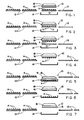
- Figs. 1-7 are schematical representations of a sequence of prior art steps performed in transferring pellets from a given tray into a furnace sintering boat.
- Fig. 8 is an enlarged fragmentary view of a plate with vacuum cups along the bottom of an overhead vacuum hood of the prior art vacuum transfer apparatus.
- Fig. 9 is an enlarged view of a portion of the plate of Fig. 8, showing one of the vacuum cups gripping a nuclear fuel pellet.
- Fig. 10 is a top plan view of the array of pellets on the tray employed in the sequence of steps of Figs. 1-7.
- Fig. 11 is an enlarged side elevational view of a nuclear fuel pellet.
- Fig. 12 is a top plan view of the pellet as seen along
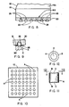
line 12--12 of Fig. 11. - Fig. 13 is a side elevational view, partly in section, of a random fuel pellet vacuum transfer apparatus in accordance with the present invention.
- Fig. 14 is a top plan view of the apparatus as seen along
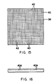
line 14--14 of Fig. 13. - Fig. 15 is a plan view of a support gridwork of the apparatus of Fig. 13.
- Fig. 16 is a side elevational view of one strip of the gridwork of Fig. 15.
- Fig. 17 is a plan view of a perforated mat of the apparatus of Fig. 13.
- Fig. 18 is a plan view of a perforated tray of the apparatus of Fig. 13.
- Referring now to the drawings, and particularly to Figs. 1-7, there is shown in schematical form a conventional transfer station, generally designated 10. At the
transfer station 10, arrays of green nuclear fuel pellets A arrive on a succession oftrays 12. The pellets A on each tray 12 (see also Fig. 10) are transferred en masse from the tray to a container orboat 14 which is then routed to a sintering furnace (not shown) for curing the pellet A. As seen in Figs. 11 and 12, each pellet A is a right cylinder with a concavity C in each of its opposite end surfaces B. - At the
transfer station 10, a prior artvacuum transfer apparatus 16 is used to carry out the transfer en masse of the pellets of each tray to theboat 14. Thevacuum transfer apparatus 16 includes anenclosure 18 in the form of an overhead hood defining aninterior vacuum chamber 18A and having an open bottom 18B and arigid plate 20 extending across and closing the hood bottom 18B. Thehood 18 per se of the prior artvacuum transfer apparatus 16 has the same construction as shown in Figs. 13 and 14. Particularly, thehood 18 has a topcylindrical portion 22 for attachment with a suitable vacuum-generating source (not shown) and a plurality (for example, four in number) ofplanar side portions 24 connected thereto which extend downwardly and outwardly in inclined fashion and are interconnected along their lateral edges so as to define theinterior hood chamber 18 in a pyramidal configuration and the hood bottom 18B in a rectangular configuration. - The
plate 20 of thevacuum transfer apparatus 16, preferably made of stainless steel and of a planar configuration, has an array ofsmall openings 26 withsmall vacuum cups 28 attached thereto. Eachvacuum cup 28 is flexible, of conical shape, and seated in one of theopenings 26 through theplate 20. Also, as best seen in Figs. 8 and 9, eachvacuum cup 28 has acentral bore 30 therethrough for communicating the vacuum in theinterior chamber 18A of thehood 18 with the upper end surface B of the one pellet A contacted by thevacuum cup 28. Registry of thevacuum cup 28 with the end surface B of the pellet A must be made with precision, particularly in view of the presence of the concavity C (see also Figs. 11 and 12) in the pellet end surface B. - One cycle of the prior art pellet transfer operation at the
transfer station 10 is schematically illustrated in Figs. 1-7. Fig. 1 depicts arrival of one of the succession of pellet-loadedtrays 12 into an unloading position at thestation 10 between theoverhead hood 18 and oneboat 14 to be loaded which is positioned below thetray 12. Fig. 2 shows thehood 18 lowered to adjacent the upper ends of the pellets A from it initial elevated position so as to forcibly expand thevacuum cups 28 against the upper end surfaces B of the pellets. A vacuum is then communicated to the end surfaces B of the pellets A from thehood 18 via theopenings 26 in theplate 20 and thebores 30 of thecups 28, as seen in Fig. 9. - Fig. 3 shows the
hood 18 raised back to it initial elevated position taking the pellets A en masse therewith from the onetray 12. As seen in Fig. 4, theempty tray 12 is then moved out of thestation 10, after which thehood 18 is lowered to adjacent theempty boat 14, as shown in Fig. 5, placing the pellets A in the boat. The vacuum is then broken permitting the pellets A to remain in the boat as thehood 18 is raised again back to its initial elevated position, as shown in Fig. 6. Finally, the loadedboat 14 is removed and replaced with another empty one, as seen in Fig. 7, and the steps are repeated again with respect to the next successive loadedtray 12. In the schematic illustration, only one layer of pellets A are shown on theboat 14, however, in actual operation there are several layers of pellets loaded into a loaded boat. - Referring now to Figs. 13-18, there is illustrated a random pellet vacuum transfer apparatus, generally designated 32, constructed in accordance with the principles of the present invention, for vacuum gripping and lifting en masse the pellets A. The random pellet
vacuum transfer apparatus 32 is employed in place of the prior artvacuum transfer apparatus 16 for carrying out the transfer of pellets A to theboat 14. - In its basic components, the
vacuum transfer apparatus 32 of the present invention includes the enclosure of overhead vacuum hood 18 (with the same construction as in the prior art apparatus 16) having thevacuum chamber 18A and open bottom 18B, a rigid structure in the form of a fixture orgridwork 34 spanning and attached to the open bottom 18B of thevacuum hood 18, and a flatperforated mat 36 attached (such as by use of an adhesive) to thegridwork 34 along a side thereof opposite from thehood 18. - Preferably, the
perforated mat 36 of theapparatus 32 is composed of resiliently flexible material, such as rubber, and has a matrix of spaced apart holes 38 of a cross-sectional, or diameter, size substantially smaller than the diameter of the typical nuclear fuel pellet A. Themat 36 has opposite upper andlower surfaces upper surface 36A in communication with thevacuum chamber 18A and opening at thelower surface 36B in communication with the pellet upper end surfaces B. - In one exemplary embodiment of the
mat 36, theholes 38 have a diameter size of 0,9 mm (0.037 in.) and center-to-center spacings of 4,5 mm (0.18 in.) with the holes arranged in a checkerboard pattern. The size of themat 36 is 280 x 280 mm (11 x 11 in.) and the hole pattern is 265 x 265 mm (10.4 x 10.4 in.). Typical pellet sizes range from 9,6 to 10,7 mm (0.38 to 0.42 in.). - As illustrated in Fig. 17, the small spacing between the
holes 38 compared to the typical diameter sizes of the pellets ensures that each pellet will be positioned beneath at least onehole 38 of theperforated mat 34 disposed above the pellets. Consequently, perfect pellet positioning beneath thevacuum transfer apparatus 32 is unnecessary. Further, the flexible, compressive material of themat 36 permits pellets of slightly differing heights to be vacuum gripped and lifted by theapparatus 32. Significant time is saved by not needing to change themat 36 for accommodating pellets of different diameter and height sizes. - The rigid fixture or
gridwork 34 of theapparatus 32 serves to back themat 36 so as to prevent themat 36 from bowing upwardly due to the vacuum from thehood 18, while at the same time permitting communication of the vacuum from theoverhead vacuum hood 18 to themat 36. Thegridwork 34, preferably of rectangular shape, is composed of a plurality of elongatedthin strips 40, one of which is seen in Fig. 16. Eachstrip 40 has spacedslots 40A open along and extending perpendicular to one longitudinal edge. Theslots 40A permit the strips to be assembled in interleaved, criss-cross fashion and rigidly attached together, such as by brazing, to define a plurality ofpassages 42 therethrough. - In one exemplary embodiment, the
strips 40 are composed of Incohel 718 material of 0,27 mm (0.0105 in.) thickness. Eachstrip 40 is 280 mm (11 in.) in length and 25 mm (1 in.) in height. Eachslot 40A in thestrips 40 is 0,30 - 0,36 mm (0.012-0.014 in.) wide by 13,5 mm (0.53 in.) deep. Thus, the size, or area, of thegridwork 34 is approximately the same as that of themat 36. Thepassages 42 have a square cross-sectional shape and cross-sectional widths of 12,5 mm (0.49 in.). Thus, the size, or cross-sectional area, of eachgridwork passage 42 is substantially larger than of eachmat hole 38. Thegridwork passages 42 communicate the vacuum from the hood through thepassages 42 to theholes 38 in themat 36 for vacuum gripping and holding the pellets A at the upper end surfaces B thereof against theflexible mat 36. Also, in view that the thickness of eachstrip 40 0,27 mm (0.0105 in.) is less than thediameter 0,9 mm (0.037 in.) of eachmat hole 38, thestrips 40 will not completely cover anyhole 38 in the mat. - In addition, referring to Fig. 18, a
perforated tray 44 is employed with thevacuum transfer apparatus 32 in place of the prior artimperforate tray 12 for supporting the plurality of fuel pellets A. The perforatedpellet support tray 44 has a plurality ofopenings 46 of substantially the same size and spacing as theholes 38 in themat 36. Those of theopenings 46 not covered by pellets A supported on thetray 44 prevent formation of a vacuum between themat 36 andtray 44 which could prevent lifting of the pellets from thetray 44. In an exemplary embodiment, thetray 44 is 3,2 mm (0.125 in.) thick and composed of a low friction material, such as Teflon composition, which permits the pellets to be slide thereon at an earlier pellet forming station (not shown).
Claims (8)
1. A vacuum transfer apparatus (32) for use in en masse vacuum gripping nuclear fuel pellets (a), said apparatus comprising
means (18) defining a vacuum chamber (18A); and
gripping means for applying the vacuum to the end surfaces (B) of the nuclear fuel pellets, characterized in that
a perforated mat (36) is attached to said vacuum chamber defining means (18, 34) and is composed of resiliently flexible material for making pressure contact with a plurality of nuclear fuel pellets (A) en masse and in a random array, said mat (36) having a matrix of spaced apart through holes (38) of a cross-sectional size substantially smaller than the diameter of the pellets (A), said holes (38) being disposed in communication with said vacuum chamber (18A) for communicating the vacuum to said pellets (A) to cause vacuum gripping and holding of the pellets (A) against said mat (36).
2. The apparatus (32) as recited in claim 1, characterized in that the vacuum chamber is defined by an enclosure (18) having an open bottom (18B);
furthermore that a rigid support structure (34) is spanning and attached to said open bottom (18B) of said enclosure (18);
said perforated mat (36) being attached to said structure (34) along a side thereof opposite from said enclosure (18),
and that said support structure (34) defines a plurality of passages (42) of a cross-sectional size substantially larger tahn that of said holes (38) in said mat (36) and provides the sole path for communicating a vacuum from said chamber (18A) of said enclosure (18) to said holes (38) in said mat (36) for vacuum gripping and holding the pellets (A) at end surfaces (B) thereof against said mat (36).
3. The apparatus (32) as recited in claim 1 or 2, characterized in that said spacing between said holes (38) in said mat (36) is smaller than the diameter of the pel lets (A).
4. The apparatus (32) as recited claim 3, characterized in that said support structure (34) is composed of a criss-crossed arrangement of parallelly-disposed and spaced apart strips (40).
5. The apparatus (32) as recited in claim 4, characterized in that the thickness of said strips (40) of said support structure (34) is less than the diameter of said holes (38) in said mat (36).
6. The apparatus (32) as recited in any of claims 3 to 5, characterized in that said support structure is a rigid support gridwork (34).
7. The apparatus (32) as recited in claims 1 to 6, characterized in that said mat (36) is composed of rubber.
8. The apparatus (32) as recited in claims 1 to 7, further characterized by:
a perforated tray (44) for supporting the fuel pellets (A) below said mat (36), said tray (44) having a plurality of openings (46) of substantially the same size and spacing as said holes (38) in said mat (36) for preventing formation of a vacuum between said mat (36) and tray (44) which could prevent lifting of the pellets (A) from said tray (44).
a perforated tray (44) for supporting the fuel pellets (A) below said mat (36), said tray (44) having a plurality of openings (46) of substantially the same size and spacing as said holes (38) in said mat (36) for preventing formation of a vacuum between said mat (36) and tray (44) which could prevent lifting of the pellets (A) from said tray (44).
Applications Claiming Priority (2)
| Application Number | Priority Date | Filing Date | Title |
|---|---|---|---|
| US373074 | 1989-06-29 | ||
| US07/373,074 US5024574A (en) | 1989-06-29 | 1989-06-29 | Random fuel pellet vacuum transfer apparatus |
Publications (1)
| Publication Number | Publication Date |
|---|---|
| EP0405171A1 true EP0405171A1 (en) | 1991-01-02 |
Family
ID=23470809
Family Applications (1)
| Application Number | Title | Priority Date | Filing Date |
|---|---|---|---|
| EP90110354A Withdrawn EP0405171A1 (en) | 1989-06-29 | 1990-05-31 | Random fuel pellet vacuum transfer apparatus |
Country Status (4)
| Country | Link |
|---|---|
| US (1) | US5024574A (en) |
| EP (1) | EP0405171A1 (en) |
| JP (1) | JPH0351798A (en) |
| KR (1) | KR910001791A (en) |
Cited By (5)
| Publication number | Priority date | Publication date | Assignee | Title |
|---|---|---|---|---|
| EP1666391A1 (en) * | 2005-08-29 | 2006-06-07 | CT Pack S.r.l. | Pneumatic system for the seizure and transfer of packs of products |
| EP2780267A4 (en) * | 2011-11-18 | 2015-11-11 | Nike Innovate Cv | VACUUM TOOL FOR MANUFACTURING |
| US9238305B2 (en) | 2011-11-18 | 2016-01-19 | Nike, Inc. | Switchable plate manufacturing vacuum tool |
| US9937585B2 (en) | 2011-11-18 | 2018-04-10 | Nike, Inc. | Multi-functional manufacturing tool |
| US12313395B2 (en) | 2011-11-18 | 2025-05-27 | Nike, Inc. | Automated 3-D modeling of shoe parts |
Families Citing this family (5)
| Publication number | Priority date | Publication date | Assignee | Title |
|---|---|---|---|---|
| SE506603C2 (en) * | 1996-05-24 | 1998-01-19 | Tepro Machine & Pac System Ab | Device with vacuum chamber for lifting and moving objects |
| DE20203307U1 (en) * | 2002-03-01 | 2003-07-10 | Avery Dennison Corp., Pasadena, Calif. | Application head for an application device |
| KR101018005B1 (en) * | 2009-06-25 | 2011-03-02 | 한전원자력연료 주식회사 | Nuclear fuel assembly |
| KR101349135B1 (en) | 2012-01-04 | 2014-01-09 | 한전원자력연료 주식회사 | Fuel pellet autoloading apparatus for manufacturing a nuclear fuel rod |
| KR102658854B1 (en) * | 2022-12-20 | 2024-04-17 | 유현 | An INSERT NUT GRIP DEVICE AND A GRIP SYSTEM USING PNEUMATIC PRESSURE |
Citations (2)
| Publication number | Priority date | Publication date | Assignee | Title |
|---|---|---|---|---|
| US3556578A (en) * | 1969-04-29 | 1971-01-19 | Corning Glass Works | Article handling |
| DE3741091A1 (en) * | 1987-12-04 | 1989-06-15 | H & K Verpackungstechnik Gmbh | Apparatus for handling piece goods |
Family Cites Families (8)
| Publication number | Priority date | Publication date | Assignee | Title |
|---|---|---|---|---|
| GB1526933A (en) * | 1974-09-13 | 1978-10-04 | Johnson Matthey Co Ltd | Vacuum head for handling transfers |
| US4009785A (en) * | 1974-10-02 | 1977-03-01 | Motorola, Inc. | Fixture and system for handling plate like objects |
| NL8006194A (en) * | 1980-11-13 | 1982-06-01 | Philips Nv | DEVICE FOR SIMULTANEOUS PLACEMENT OF MULTIPLE ELECTRICAL AND / OR ELECTRONIC COMPONENTS ON A PRINTED WIRING PANEL. |
| FR2495592A1 (en) * | 1980-12-05 | 1982-06-11 | Joulin Sema | GRIPPING DEVICE OPERATING BY SUCCION |
| US4778326A (en) * | 1983-05-24 | 1988-10-18 | Vichem Corporation | Method and means for handling semiconductor and similar electronic devices |
| US4635365A (en) * | 1983-09-09 | 1987-01-13 | Dainippon Screen Seizo Kabushiki Kaisha | Coordinate plotter with automatic punching device |
| US4712784A (en) * | 1985-05-31 | 1987-12-15 | Rca Corporation | Adjustable vacuum pad |
| DE3543152A1 (en) * | 1985-12-06 | 1987-06-11 | Lewecke Gmbh Maschbau | VACUUM LIFTER |
-
1989
- 1989-06-29 US US07/373,074 patent/US5024574A/en not_active Expired - Fee Related
-
1990
- 1990-05-31 EP EP90110354A patent/EP0405171A1/en not_active Withdrawn
- 1990-06-28 KR KR1019900009649A patent/KR910001791A/en not_active Withdrawn
- 1990-06-29 JP JP2174300A patent/JPH0351798A/en active Pending
Patent Citations (2)
| Publication number | Priority date | Publication date | Assignee | Title |
|---|---|---|---|---|
| US3556578A (en) * | 1969-04-29 | 1971-01-19 | Corning Glass Works | Article handling |
| DE3741091A1 (en) * | 1987-12-04 | 1989-06-15 | H & K Verpackungstechnik Gmbh | Apparatus for handling piece goods |
Non-Patent Citations (1)
| Title |
|---|
| PATENT ABSTRACTS OF JAPAN, vol. 9, no. 279 (M-427)[2002], 7th November 1985; & JP-A-60 122 618 (KOUWA KOGYO) * |
Cited By (14)
| Publication number | Priority date | Publication date | Assignee | Title |
|---|---|---|---|---|
| EP1666391A1 (en) * | 2005-08-29 | 2006-06-07 | CT Pack S.r.l. | Pneumatic system for the seizure and transfer of packs of products |
| EP2780267A4 (en) * | 2011-11-18 | 2015-11-11 | Nike Innovate Cv | VACUUM TOOL FOR MANUFACTURING |
| US9238305B2 (en) | 2011-11-18 | 2016-01-19 | Nike, Inc. | Switchable plate manufacturing vacuum tool |
| US9403280B2 (en) | 2011-11-18 | 2016-08-02 | Nike, Inc. | Manufacturing vacuum tool |
| US9937585B2 (en) | 2011-11-18 | 2018-04-10 | Nike, Inc. | Multi-functional manufacturing tool |
| US9937627B2 (en) | 2011-11-18 | 2018-04-10 | Nike, Inc. | Manufacturing vacuum tool with selective activation of pickup zones |
| US10272518B2 (en) | 2011-11-18 | 2019-04-30 | Nike, Inc. | Multi-functional manufacturing tool |
| US10532468B2 (en) | 2011-11-18 | 2020-01-14 | Nike, Inc. | Manufacturing vacuum tool with selective activation of pickup zones |
| US10610958B2 (en) | 2011-11-18 | 2020-04-07 | Nike, Inc. | Multi-functional manufacturing tool |
| EP3753691A1 (en) * | 2011-11-18 | 2020-12-23 | NIKE Innovate C.V. | Manufacturing vacuum tool |
| US11273514B2 (en) | 2011-11-18 | 2022-03-15 | Nike, Inc. | Multi-functional manufacturing tool |
| US11389972B2 (en) | 2011-11-18 | 2022-07-19 | Nike, Inc. | Manufacturing tool with selective activation of pickup zones |
| US11911893B2 (en) | 2011-11-18 | 2024-02-27 | Nike, Inc. | Manufacturing tool |
| US12313395B2 (en) | 2011-11-18 | 2025-05-27 | Nike, Inc. | Automated 3-D modeling of shoe parts |
Also Published As
| Publication number | Publication date |
|---|---|
| US5024574A (en) | 1991-06-18 |
| KR910001791A (en) | 1991-01-31 |
| JPH0351798A (en) | 1991-03-06 |
Similar Documents
| Publication | Publication Date | Title |
|---|---|---|
| EP0405171A1 (en) | Random fuel pellet vacuum transfer apparatus | |
| AU732513B2 (en) | Support rack for pipette tips | |
| US7981246B2 (en) | Method and device for detaching a component which is attached to a flexible film | |
| JP3093264B2 (en) | Control device for electronic device test | |
| US20020135190A1 (en) | Device and method for picking up and placing objects | |
| EP1491898B1 (en) | Methods and apparatus for handling compound storage vessels | |
| EP1041864A2 (en) | Supporting plate for flexible base supports for electronic circuits | |
| CN214827297U (en) | Ceramic filter production equipment, isolation gasket placement mechanism | |
| US5046917A (en) | Apparatus for forming stacks of accumulator plates | |
| US6227787B1 (en) | Device for loading workpiece pallets | |
| US5053183A (en) | Method of handling green ceramic cards | |
| JP3619122B2 (en) | Method and apparatus for firing element with hole | |
| JPH10218402A (en) | Method and device for picking up and transferring soft sheet | |
| JPH0543184B2 (en) | ||
| JPH0787941A (en) | Dividing plate and device for taking out the same | |
| JP2001066069A (en) | Baking setter | |
| JP4744006B2 (en) | Method and apparatus for gripping an article | |
| JP3929633B2 (en) | Sheet stock equipment | |
| CN114789912B (en) | Ceramic filter production facility, isolation gasket placement machine constructs | |
| JPH02225206A (en) | Aligning method of disk-shaped parts and device therefor | |
| US3648865A (en) | Article handling | |
| JP2002502136A (en) | Element positioning device | |
| JPS61155135A (en) | How to transfer a plate-shaped object | |
| KR200241555Y1 (en) | A wafer transmission arm | |
| JPS6260716A (en) | Equi-interval arranging method and device for powder mold |
Legal Events
| Date | Code | Title | Description |
|---|---|---|---|
| PUAI | Public reference made under article 153(3) epc to a published international application that has entered the european phase |
Free format text: ORIGINAL CODE: 0009012 |
|
| AK | Designated contracting states |
Kind code of ref document: A1 Designated state(s): BE DE ES FR GB IT SE |
|
| 17P | Request for examination filed |
Effective date: 19901221 |
|
| STAA | Information on the status of an ep patent application or granted ep patent |
Free format text: STATUS: THE APPLICATION IS DEEMED TO BE WITHDRAWN |
|
| 18D | Application deemed to be withdrawn |
Effective date: 19921202 |