EP0404400A2 - Energieversorgung mit begrenzter Spannung und begrenztem Strom - Google Patents
Energieversorgung mit begrenzter Spannung und begrenztem Strom Download PDFInfo
- Publication number
- EP0404400A2 EP0404400A2 EP90306224A EP90306224A EP0404400A2 EP 0404400 A2 EP0404400 A2 EP 0404400A2 EP 90306224 A EP90306224 A EP 90306224A EP 90306224 A EP90306224 A EP 90306224A EP 0404400 A2 EP0404400 A2 EP 0404400A2
- Authority
- EP
- European Patent Office
- Prior art keywords
- voltage
- current
- load
- circuit
- current source
- Prior art date
- Legal status (The legal status is an assumption and is not a legal conclusion. Google has not performed a legal analysis and makes no representation as to the accuracy of the status listed.)
- Withdrawn
Links
Images
Classifications
-
- G—PHYSICS
- G05—CONTROLLING; REGULATING
- G05F—SYSTEMS FOR REGULATING ELECTRIC OR MAGNETIC VARIABLES
- G05F1/00—Automatic systems in which deviations of an electric quantity from one or more predetermined values are detected at the output of the system and fed back to a device within the system to restore the detected quantity to its predetermined value or values, i.e. retroactive systems
- G05F1/10—Regulating voltage or current
- G05F1/46—Regulating voltage or current wherein the variable actually regulated by the final control device is DC
- G05F1/56—Regulating voltage or current wherein the variable actually regulated by the final control device is DC using semiconductor devices in series with the load as final control devices
- G05F1/565—Regulating voltage or current wherein the variable actually regulated by the final control device is DC using semiconductor devices in series with the load as final control devices sensing a condition of the system or its load in addition to means responsive to deviations in the output of the system, e.g. current, voltage, power factor
- G05F1/569—Regulating voltage or current wherein the variable actually regulated by the final control device is DC using semiconductor devices in series with the load as final control devices sensing a condition of the system or its load in addition to means responsive to deviations in the output of the system, e.g. current, voltage, power factor for protection
Definitions
- the invention relates to power supplies and more particularly to an improved power supply capable of supplying a predetermined voltage and current to a load and which will not exceed a predetermined maximum output voltage when the load is disconnected from the power supply or a predetermined maximum current when the load is short circuited.
- the amount of current available to the load is limited by the series resistance of the zener barrier circuit and the characteristic input impedance of the load device.
- the available voltage is clamped by the zener diodes to a level above the normal operating voltage for the load, but the current is only limited by the series resistance of the zener barrier circuit.
- the available current may be much higher than the normal operating current of the load.
- the power supply of the invention differs from the prior art in that the maximum current and voltage available at the load are limited to substantially that current and voltage required to operate the load.
- the available current is limited through the use of a constant current power source and the maximum voltage is limited both by the maximum output voltage from the constant current power source and by a conventional zener barrier circuit.
- the output current from the power source, the resistance of the load and the series resistance of the zener barrier circuit determine the voltage applied to the load by the current source.
- the constant current source provides the required total voltage at the designated current level and adjusts for fluctuations in the input source voltage. If the load becomes detached in an explosive environment, either the maximum voltage capability of the constant current source or the zener diodes will establish the maximum output voltage. However, the maximum available current for ignition is no more than with the load attached by virtue of the constant current source maintaining and limiting the available current.
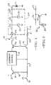
- a voltage and current limiting power supply circuit 10 is shown according to a preferred embodiment of the invention.
- the illustrated and described circuit 10 is designed to supply 12 volts dc at 42 ma. to a valve actuating solenoid 11 located in a hazardous environment, such as a paint spray booth.
- a conventional low voltage power source not shown
- a 15 volt dc power supply connected between positive terminals 12 and ground.
- the power supply circuit 10 is controlled by an input switching circuit including a switch 13 and three transistors 14, 15 and 16.
- the switch 13 is connected between a terminal 17 and ground.
- the terminal 17 is connected through a resistor 18 to the base of the transistor 14.
- the emitter of the transistor 14 is connected to one positive terminal 12 and the collector of the transistor 14 is connected to the input to a constant current source 19.
- the switch 13 is closed, the transistor 14 conducts to apply 15 volts dc from the terminal 12 to operate the current source 19.
- the current source 19 is designed to have a constant current output of 45 ma.
- the output voltage of the current source 19 will vary, depending on the load, up to a maximum of about 15 volts. The maximum output voltage is limited by the magnitude of the input voltage.
- the switched terminal 17 also is connected through the emitter and collector of the transistor 15, a resistor 20 and an LED 21 to one of the positive terminals 12.
- the transistor 15 conducts to allow current to flow through the LED 21, thereby producing a warning light to indicate that the circuit 10 is operating.
- the base of the transistor 15 is coupled through a resistor 22 to the base of the transistor 16.
- the transistor 15 turns on the transistor 16 to apply power from the current source 19 through a fuse 23 and a zener barrier circuit 24 to the valve solenoid 11.
- the diode 25 protects the transistor 16 and the current source 19 from damage in the event that a voltage or transient from an external source is applied to the output 29.
- the junction between the resistors 26 and 27 is connected through a zener diode 30 to ground and the junction between the resistors 27 and 28 is connected through a zener diode 31 to ground. So long as the maximum voltage from the current source 19 is at a safe level, the zener diodes 30 and 31 will have a breakdown voltage above such maximum voltage, for example, of about 20 volts.
- the current source 19 is turned on and 12 volts at 42 ma is applied to the valve solenoid 11.
- the maximum current is limited to the 45 ma available from the current source.
- the maximum voltage available at the output 29 is the maximum output voltage from the current source 19, or about 15 volts.
- the output 29 is clamped to 20 volts by the zener barrier 24.
- the zener diodes 30 and 31 may be selected with lower breakdown voltages for clamping the output to a voltage less than the maximum output voltage from the current source 19.
- the zener diodes 30 and 31 of Fig. 1 may be replaced with other types of voltage limiting devices, such as the device 32 illustrated in Fig. 2.
- the device 32 is an amplified zener circuit consisting of a power transistor 33 and a zener diode 34 which are illustrated connected between the resistors 26 and 27 and ground.
- the emitter of the transistor 33 is connected to the junction between the resistors 26 and 27 and the collector is connected to ground.
- the zener diode 34 is connected from the base of the transistor 33 to ground.
- the power transistor 33 simulates a higher power zener diode in that it is capable of handling greater current than the zener diode while limiting the voltage between the emitter and ground.
Landscapes
- Engineering & Computer Science (AREA)
- Physics & Mathematics (AREA)
- Electromagnetism (AREA)
- General Physics & Mathematics (AREA)
- Radar, Positioning & Navigation (AREA)
- Automation & Control Theory (AREA)
- Electrostatic Spraying Apparatus (AREA)
- Control Of Voltage And Current In General (AREA)
- Continuous-Control Power Sources That Use Transistors (AREA)
- Emergency Protection Circuit Devices (AREA)
Applications Claiming Priority (2)
| Application Number | Priority Date | Filing Date | Title |
|---|---|---|---|
| US369024 | 1989-06-20 | ||
| US07/369,024 US4979067A (en) | 1989-06-20 | 1989-06-20 | Voltage and current limiting power supply |
Publications (2)
| Publication Number | Publication Date |
|---|---|
| EP0404400A2 true EP0404400A2 (de) | 1990-12-27 |
| EP0404400A3 EP0404400A3 (de) | 1991-08-07 |
Family
ID=23453745
Family Applications (1)
| Application Number | Title | Priority Date | Filing Date |
|---|---|---|---|
| EP19900306224 Withdrawn EP0404400A3 (de) | 1989-06-20 | 1990-06-07 | Energieversorgung mit begrenzter Spannung und begrenztem Strom |
Country Status (6)
| Country | Link |
|---|---|
| US (1) | US4979067A (de) |
| EP (1) | EP0404400A3 (de) |
| JP (1) | JPH0330005A (de) |
| AU (1) | AU640656B2 (de) |
| BR (1) | BR9002897A (de) |
| CA (1) | CA1313690C (de) |
Families Citing this family (20)
| Publication number | Priority date | Publication date | Assignee | Title |
|---|---|---|---|---|
| US4806040A (en) * | 1987-02-12 | 1989-02-21 | Cummins Engine Company, Inc. | Ceramic ball and socket joint |
| US4966108A (en) * | 1989-04-28 | 1990-10-30 | Cummins Engine Company, Inc. | Sintered ceramic ball and socket joint assembly |
| JP2993210B2 (ja) * | 1991-09-10 | 1999-12-20 | 松下電器産業株式会社 | 電源回路の保護装置 |
| DE4433045A1 (de) * | 1994-09-16 | 1996-03-21 | Bosch Gmbh Robert | Elektronische Einrichtung |
| EP0782235B1 (de) * | 1995-12-29 | 2001-11-14 | STMicroelectronics S.r.l. | Verfahren zum Schutz von Leistungstransistoren und übereinstimmende Schaltung |
| FR2769142B1 (fr) * | 1997-09-29 | 1999-12-17 | Sgs Thomson Microelectronics | Circuit de protection associable a un filtre |
| DE20005927U1 (de) * | 1999-03-31 | 2000-10-19 | Pepperl & Fuchs GmbH, 68307 Mannheim | Sicherheitsbarriere zum Begrenzen von Strom und Spannung |
| US6397322B1 (en) * | 2000-03-31 | 2002-05-28 | Schneider Automation, Inc. | Integrated intrinsically safe input-output module |
| WO2007064886A2 (en) * | 2005-12-02 | 2007-06-07 | Kent Mcguire | Spray booth and method for coating the human body with sunscreen or the like |
| JP4792557B2 (ja) * | 2006-03-28 | 2011-10-12 | 独立行政法人日本原子力研究開発機構 | コンテナ |
| GB0610202D0 (en) * | 2006-05-23 | 2006-07-05 | Pepperl & Fuchs Gb Ltd | Electrical barrier |
| JP4864622B2 (ja) * | 2006-09-27 | 2012-02-01 | 株式会社ケーヒン | 誘導性負荷の駆動装置 |
| TWM313372U (en) * | 2006-11-01 | 2007-06-01 | Polytronics Technology Corp | Over-current and over-voltage protection assembly apparatus |
| JP4786735B2 (ja) * | 2009-08-10 | 2011-10-05 | 中国電力株式会社 | 気密判定装置及び気密判定方法 |
| JP5545511B2 (ja) | 2012-05-23 | 2014-07-09 | 横河電機株式会社 | バルブ遠隔操作装置 |
| DE102013215077A1 (de) * | 2013-08-01 | 2015-02-05 | Siemens Aktiengesellschaft | Feldgerät zur Prozessinstrumentierung |
| JP6007922B2 (ja) * | 2014-01-07 | 2016-10-19 | 横河電機株式会社 | 接点信号変換装置 |
| JP6476835B2 (ja) * | 2014-06-13 | 2019-03-06 | 横河電機株式会社 | 信号変換装置 |
| US10670054B2 (en) * | 2017-10-25 | 2020-06-02 | Dresser, Llc | Constructing valve positioners for hazardous areas |
| US10749426B1 (en) | 2019-04-11 | 2020-08-18 | Graco Minnesota Inc. | Trapezoidal power-supply barrier between hazardous and normal locations |
Family Cites Families (7)
| Publication number | Priority date | Publication date | Assignee | Title |
|---|---|---|---|---|
| US3678370A (en) * | 1970-10-30 | 1972-07-18 | Forbro Design Corp | Voltage limiting circuit for constant current power supplies |
| JPS5239717Y2 (de) * | 1972-04-14 | 1977-09-08 | ||
| IT1055625B (it) * | 1975-10-09 | 1982-01-11 | Indesit | Circuito di alimentazione stabiliz zato |
| US4099216A (en) * | 1976-11-12 | 1978-07-04 | Westinghouse Electric Corp. | Fuseless intrinsic safety barrier |
| US4412265A (en) * | 1981-11-27 | 1983-10-25 | Tokheim Corporation | Intrinsic barrier |
| US4485427A (en) * | 1982-04-19 | 1984-11-27 | Ransburg Corporation | Fold-back power supply |
| GB8722679D0 (en) * | 1987-09-26 | 1987-11-04 | Measurement Tech Ltd | Electrical safety barriers |
-
1989
- 1989-06-20 US US07/369,024 patent/US4979067A/en not_active Expired - Fee Related
- 1989-09-08 CA CA000610702A patent/CA1313690C/en not_active Expired - Fee Related
-
1990
- 1990-06-04 AU AU56258/90A patent/AU640656B2/en not_active Ceased
- 1990-06-07 EP EP19900306224 patent/EP0404400A3/de not_active Withdrawn
- 1990-06-18 JP JP2159600A patent/JPH0330005A/ja active Pending
- 1990-06-20 BR BR909002897A patent/BR9002897A/pt unknown
Also Published As
| Publication number | Publication date |
|---|---|
| US4979067A (en) | 1990-12-18 |
| AU5625890A (en) | 1991-01-03 |
| BR9002897A (pt) | 1991-08-20 |
| EP0404400A3 (de) | 1991-08-07 |
| JPH0330005A (ja) | 1991-02-08 |
| CA1313690C (en) | 1993-02-16 |
| AU640656B2 (en) | 1993-09-02 |
Similar Documents
| Publication | Publication Date | Title |
|---|---|---|
| US4979067A (en) | Voltage and current limiting power supply | |
| US5004972A (en) | Integrated power level control and on/off function circuit | |
| US4508954A (en) | Portable arc voltage wirefeed welding system | |
| US4716490A (en) | Power saving module | |
| US5404094A (en) | Wide input power supply and method of converting therefor | |
| EP3273560A1 (de) | Ideale diode mit aktivem sperrspannungsschutz | |
| US10270240B2 (en) | Surge protective device with abnormal overvoltage protection | |
| US6144539A (en) | Arrangement for protecting low-voltage control circuitry from externally applied high voltages, and dimming ballast employing such an arrangement | |
| EP0408059A2 (de) | Steuergerät für einen Fahrzeugwechselstromgenerator | |
| US4943761A (en) | Current limited DC power controller | |
| KR20000010878A (ko) | 과전압으로부터 보호하기 위한 장치 및 방법 | |
| US5202811A (en) | Electrical power system with high voltage protection responsive to plural control voltages | |
| US4439721A (en) | Magneto alternator regulator with tachometer output | |
| US5028862A (en) | Voltage follower circuit for use in power level control circuits | |
| CA2170696A1 (en) | Step down transformer power supply with short circuit protection | |
| US4779027A (en) | DC to DC converter with overvoltage protection circuit | |
| US4251764A (en) | Interface circuit for interconnecting an electronic controller to a resistance welding machine | |
| US7154732B2 (en) | Apparatus and system for controlling a squib firing device | |
| US7482758B2 (en) | Magnetic low voltage dimmer | |
| US3809963A (en) | Power supply system control circuit | |
| US4517618A (en) | Protection circuitry for high voltage drivers | |
| US4193104A (en) | Programmable overvoltage protector | |
| US4400756A (en) | Inductive load driver protection circuits having minimal power dissipation | |
| JPS59136028A (ja) | 直流安定化電源の保護装置 | |
| JP2704588B2 (ja) | 過電流保護装置 |
Legal Events
| Date | Code | Title | Description |
|---|---|---|---|
| PUAI | Public reference made under article 153(3) epc to a published international application that has entered the european phase |
Free format text: ORIGINAL CODE: 0009012 |
|
| AK | Designated contracting states |
Kind code of ref document: A2 Designated state(s): BE DE FR GB IT |
|
| PUAL | Search report despatched |
Free format text: ORIGINAL CODE: 0009013 |
|
| AK | Designated contracting states |
Kind code of ref document: A3 Designated state(s): BE DE FR GB IT |
|
| RHK1 | Main classification (correction) |
Ipc: G05F 1/571 |
|
| 17P | Request for examination filed |
Effective date: 19920109 |
|
| 17Q | First examination report despatched |
Effective date: 19931115 |
|
| RAP1 | Party data changed (applicant data changed or rights of an application transferred) |
Owner name: ABB FLEXIBLE AUTOMATION GMBH |
|
| STAA | Information on the status of an ep patent application or granted ep patent |
Free format text: STATUS: THE APPLICATION IS DEEMED TO BE WITHDRAWN |
|
| 18D | Application deemed to be withdrawn |
Effective date: 19950909 |