EP0404348A1 - Friction stay - Google Patents
Friction stay Download PDFInfo
- Publication number
- EP0404348A1 EP0404348A1 EP90305535A EP90305535A EP0404348A1 EP 0404348 A1 EP0404348 A1 EP 0404348A1 EP 90305535 A EP90305535 A EP 90305535A EP 90305535 A EP90305535 A EP 90305535A EP 0404348 A1 EP0404348 A1 EP 0404348A1
- Authority
- EP
- European Patent Office
- Prior art keywords
- slider
- track
- cam
- recess
- pivotally connected
- Prior art date
- Legal status (The legal status is an assumption and is not a legal conclusion. Google has not performed a legal analysis and makes no representation as to the accuracy of the status listed.)
- Withdrawn
Links
- 229920003023 plastic Polymers 0.000 claims description 5
- 239000004033 plastic Substances 0.000 claims description 5
- 239000000463 material Substances 0.000 claims description 3
- DHKHKXVYLBGOIT-UHFFFAOYSA-N acetaldehyde Diethyl Acetal Natural products CCOC(C)OCC DHKHKXVYLBGOIT-UHFFFAOYSA-N 0.000 description 4
- 150000001241 acetals Chemical class 0.000 description 3
- 239000002184 metal Substances 0.000 description 3
- 229910052751 metal Inorganic materials 0.000 description 3
- 229920001577 copolymer Polymers 0.000 description 2
- 229920001519 homopolymer Polymers 0.000 description 2
- 238000000465 moulding Methods 0.000 description 2
- 235000020637 scallop Nutrition 0.000 description 2
- 229910001369 Brass Inorganic materials 0.000 description 1
- 241000237509 Patinopecten sp. Species 0.000 description 1
- 241000237503 Pectinidae Species 0.000 description 1
- 229910000831 Steel Inorganic materials 0.000 description 1
- HCHKCACWOHOZIP-UHFFFAOYSA-N Zinc Chemical compound [Zn] HCHKCACWOHOZIP-UHFFFAOYSA-N 0.000 description 1
- 229910001297 Zn alloy Inorganic materials 0.000 description 1
- 239000011354 acetal resin Substances 0.000 description 1
- 239000010951 brass Substances 0.000 description 1
- 230000007797 corrosion Effects 0.000 description 1
- 238000005260 corrosion Methods 0.000 description 1
- 230000000694 effects Effects 0.000 description 1
- 239000004519 grease Substances 0.000 description 1
- 229920006324 polyoxymethylene Polymers 0.000 description 1
- 238000007788 roughening Methods 0.000 description 1
- 239000010959 steel Substances 0.000 description 1
- 229910052725 zinc Inorganic materials 0.000 description 1
- 239000011701 zinc Substances 0.000 description 1
Images

Classifications
-
- E—FIXED CONSTRUCTIONS
- E05—LOCKS; KEYS; WINDOW OR DOOR FITTINGS; SAFES
- E05D—HINGES OR SUSPENSION DEVICES FOR DOORS, WINDOWS OR WINGS
- E05D15/00—Suspension arrangements for wings
- E05D15/40—Suspension arrangements for wings supported on arms movable in vertical planes
- E05D15/44—Suspension arrangements for wings supported on arms movable in vertical planes with pivoted arms and vertically-sliding guides
-
- E—FIXED CONSTRUCTIONS
- E05—LOCKS; KEYS; WINDOW OR DOOR FITTINGS; SAFES
- E05Y—INDEXING SCHEME ASSOCIATED WITH SUBCLASSES E05D AND E05F, RELATING TO CONSTRUCTION ELEMENTS, ELECTRIC CONTROL, POWER SUPPLY, POWER SIGNAL OR TRANSMISSION, USER INTERFACES, MOUNTING OR COUPLING, DETAILS, ACCESSORIES, AUXILIARY OPERATIONS NOT OTHERWISE PROVIDED FOR, APPLICATION THEREOF
- E05Y2900/00—Application of doors, windows, wings or fittings thereof
- E05Y2900/10—Application of doors, windows, wings or fittings thereof for buildings or parts thereof
- E05Y2900/13—Type of wing
- E05Y2900/132—Doors
Definitions
- This invention relates to friction supporting stays of the type which are used for supporting windows and sometimes doors, the stay being of the kind which comprises a track, a slider movable along the track, a strut pivotally connected to the track, a brace pivotally connected between the slider and the strut, a link pivotally connected to the slider and a bar pivotally connected to the link and the strut, the arrangement being such that as the slider moves along the track the bar can swing from a position overlying the track to a position where it is angled with respect to the track.
- Control of the frictional restraint of the slider in known friction stays is achieved by use of a friction pad located between the slider and the track and a grub screw threaded in the body of the slider and adapted to bear directly on the friction pad so that the frictional engagement between the slider and the track may be varied.
- the pad bears downwardly on the base of the track which is where the frictional engagement occurs.
- An object of the present invention is to provide an improved form of slider which is cheaper to produce, can be made without any metal parts if desired, and is efficient in operation.
- a slider for a track comprising a slider body adapted to be slidably received in the track, and said body including a recess having mounted therein a cam which is rotatable so as to bear against the sides of the recess, whereby to vary the frictional engagement of the slider with the track.
- a friction stay comprising a track, a slider comprising a slider body movable along the track, a strut pivotally connected to the track, a brace pivotally connected between the slider and the strut, a link pivotally connected to the slider and a bar pivotally connected to the link and to the strut, the arrangement being such that as the slider moves along the track the bar can swing from a position overlying the track to a position where it is angled with respect to the track, characterised in that the slider body includes a recess having mounted therein a cam which is rotatable so as to bear against the sides of the recess, whereby to vary the frictional engagement of the slider with the track.
- the track is of channel section, and rotation of the cam to bear against the sides of the recess causes the longitudinal edges of the slider to bear against the walls of the channel.
- the walls of the channel may be flanged, and the longitudinal edges of the slider may be adapted to receive said flanges.
- the slider body is preferably formed from a plastics material. Acetal homopolymers and copolymers are particularly preferred because of their low friction, low wear properties.
- the cam may also be made from a plastics material such as an acetal homopolymer or copolymer.
- the cam may be made from a metal such as brass, steel or a zinc alloy of the kind sold under the Trade Mark Mazak. If desired, the cam may be zinc plated to improve corrosion resistance.
- the cam preferably forms a friction fit in the recess, so that it is rotatable against the friction between the two parts, but not freely rotatable. If necessary, friction between the cam and the slider body may be increased by knurling or otherwise roughening one or both of the cooperating surfaces. For example, if a metal cam is received in an acetal slider body, the cooperating surface of the cam may conveniently be provided with knurling in a saw-tooth pattern to a depth of 0.1mm, with a pitch of 0.2mm. If both the cam and the slider body are formed from an acetal resin, knurling is not generally necessary.
- the cam may be arranged with a downwardly projecting boss on which there is a flange engageable in a corresponding hole in the lower part of the slider body so that the cam clicks into and is held in place in the slider body.
- a drive recess or slot in the cam to enable it to be rotated and thus to vary the pressure on the sides of the recess.
- the recess or slot may be e.g. a hexagonal or square recess or a screwdriver slot.
- the slider body is scalloped at its outer edges adjacent the recess so that when the cam applies pressure to the internal walls of the recess the scalloped portions tend to be straightened thus bringing a straight portion of the slider body into contact with the adjacent walls of the track.
- a straight sided slider may be used or slots may be formed in the ends of the walls to allow the outwardly facing portions of the walls to bow outwardly.
- the cam may, for example, be symmetrical and have two parallel straight portions joined by French curves.
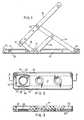
- the friction supporting stay shown in Figure 1 comprises a track 10 which has flanged outer walls 11 and 12 and a nose portion 13.
- a strut 14 is pivotally connected to the track 10 at 15.
- a brace 16 is pivotally connected between the strut 14 and a slider 17.
- a link 18 is pivotally connected between the slider 17 and a bar 19 which is in turn pivoted at 20 to the link 14.
- the bar 19 carries a plastic nose portion 21.
- the body of the slider shown in underplan view in Figure 2, has a recess 22 of substantially rectangular shape and the bottom of the recess is formed with a holding frame 23 adapted to receive a corresponding flange on a cam 24 shown in Figures 4 to 8.
- the cam 24 has a boss 25 formed at its outer end with a tapered flange 26 which is adapted to engage the flange 23 in the slider body so as to retain the cam in the slider body but to allow it to rotate when turned by a screwdriver or similar tool engageable in a slot 27.
- the outer surface of the cam comprises two parallel straight portions 28 and 29 joined by French curves 30 and 31.
- the outer walls of the slider are formed with spaced apart parallel lips 32 and 33 which engage over the flanges 11 and 12 of the side walls of the track 10.
- the lips 32 are scalloped at 34 and 35 as seen in Figures 2 and 6.
- the cam 24 is shown in Figure 6 with the straight portions 28 and 29 in contact with the inner walls of the recess 22.
- the curved portions 30 and 31 of the cam engage the inner walls of the recess thus forcing the scalloped lips 34 and 35 to come into contact with the inner surface of the side walls 38 and 39 of the track 17.
- the scallops have now straightened out and thus there is line frictional contact at 36 and 37 between the outer edges of the slider and the inner portions of the walls of the track.
- the degree of frictional contact will vary according to the position of the cam 24 and thus the resistance to movement of the slider in the track 10 can be varied so as to provide the required holding force when the friction stay is in its open position.
- FIG. 2A Another arrangement which achieves a similar effect to the scallop is shown in Figure 2A.
- the walls 22 are straight but at each end of each wall 22 is a slot 22a which weakens each wall 22b and allows it to bow outwardly when the cam 24 is rotated thus causing each wall 22b to grip the track.
- the slider body is preferably moulded from plastic and may be moulded in the form of a single moulding which may also encompass the cam.
- the slider of the invention is simpler and cheaper to produce than conventional sliders.
- This novel slider may be applied to any supporting stay whether for windows or doors, whether for use as a horizontal or vertical support and indeed wherever variable friction is required between a slider and a track.
- the invention may be applied to any of the well known Securistyle range of friction supporting stays such as those illustrated in British Patent 2081803B and European Patent 0295094.
Landscapes
- Engineering & Computer Science (AREA)
- Mechanical Engineering (AREA)
- Drawers Of Furniture (AREA)
- Bearings For Parts Moving Linearly (AREA)
- Support Devices For Sliding Doors (AREA)
- Supports Or Holders For Household Use (AREA)
- Braking Arrangements (AREA)
Abstract
A slider (17) for a track (10), such as the track of a friction stay, comprises a slider body (17) adapted to be slidably received in the track, and the slider body includes a recess (22) having a cam (24) mounted therein. Rotation of the cam causes it to bear against the sides of the recess, which are thereby slightly deformed. This deformation increases the frictional engagement of the slider with the track.
Description
- This invention relates to friction supporting stays of the type which are used for supporting windows and sometimes doors, the stay being of the kind which comprises a track, a slider movable along the track, a strut pivotally connected to the track, a brace pivotally connected between the slider and the strut, a link pivotally connected to the slider and a bar pivotally connected to the link and the strut, the arrangement being such that as the slider moves along the track the bar can swing from a position overlying the track to a position where it is angled with respect to the track.
- Control of the frictional restraint of the slider in known friction stays is achieved by use of a friction pad located between the slider and the track and a grub screw threaded in the body of the slider and adapted to bear directly on the friction pad so that the frictional engagement between the slider and the track may be varied. The pad bears downwardly on the base of the track which is where the frictional engagement occurs.
- An object of the present invention is to provide an improved form of slider which is cheaper to produce, can be made without any metal parts if desired, and is efficient in operation.
- In accordance with the present invention, there is provided a slider for a track, said slider comprising a slider body adapted to be slidably received in the track, and said body including a recess having mounted therein a cam which is rotatable so as to bear against the sides of the recess, whereby to vary the frictional engagement of the slider with the track.
- Also provided in accordance with the present invention is a friction stay comprising a track, a slider comprising a slider body movable along the track, a strut pivotally connected to the track, a brace pivotally connected between the slider and the strut, a link pivotally connected to the slider and a bar pivotally connected to the link and to the strut, the arrangement being such that as the slider moves along the track the bar can swing from a position overlying the track to a position where it is angled with respect to the track, characterised in that the slider body includes a recess having mounted therein a cam which is rotatable so as to bear against the sides of the recess, whereby to vary the frictional engagement of the slider with the track.
- In one embodiment, the track is of channel section, and rotation of the cam to bear against the sides of the recess causes the longitudinal edges of the slider to bear against the walls of the channel. The walls of the channel may be flanged, and the longitudinal edges of the slider may be adapted to receive said flanges.
- The slider body is preferably formed from a plastics material. Acetal homopolymers and copolymers are particularly preferred because of their low friction, low wear properties.
- The cam may also be made from a plastics material such as an acetal homopolymer or copolymer. Alternatively, the cam may be made from a metal such as brass, steel or a zinc alloy of the kind sold under the Trade Mark Mazak. If desired, the cam may be zinc plated to improve corrosion resistance.
- The cam preferably forms a friction fit in the recess, so that it is rotatable against the friction between the two parts, but not freely rotatable. If necessary, friction between the cam and the slider body may be increased by knurling or otherwise roughening one or both of the cooperating surfaces. For example, if a metal cam is received in an acetal slider body, the cooperating surface of the cam may conveniently be provided with knurling in a saw-tooth pattern to a depth of 0.1mm, with a pitch of 0.2mm. If both the cam and the slider body are formed from an acetal resin, knurling is not generally necessary.
- The cam may be arranged with a downwardly projecting boss on which there is a flange engageable in a corresponding hole in the lower part of the slider body so that the cam clicks into and is held in place in the slider body.
- Preferably there is a drive recess or slot in the cam to enable it to be rotated and thus to vary the pressure on the sides of the recess. The recess or slot may be e.g. a hexagonal or square recess or a screwdriver slot.
- In one embodiment the slider body is scalloped at its outer edges adjacent the recess so that when the cam applies pressure to the internal walls of the recess the scalloped portions tend to be straightened thus bringing a straight portion of the slider body into contact with the adjacent walls of the track. Alternatively a straight sided slider may be used or slots may be formed in the ends of the walls to allow the outwardly facing portions of the walls to bow outwardly.
- The cam may, for example, be symmetrical and have two parallel straight portions joined by French curves.
- In the accompanying drawings:-
- Figure 1 is a plan view of a friction supporting stay embodying the invention;
- Figure 2 is an enlarged underplan of a slider which is shown in Figure 1;
- Figure 2A is a modified version of the left-hand portion of Figure 2;
- Figure 3 is a section on line 3-3 of Figure 2;
- Figure 4 is an enlarged plan view of the cam which is incorporated in the slider;
- Figure 5 is an elevation of a cam shown in Figure 4;
- Figure 6 is a fragmentary underplan with the track broken away to show the cam in its unlocked or free position;
- Figure 7 is a view similar to Figure 6 but shows the cam in its locked or engaged position; and
- Figure 8 is a section on line 8-8 of Figure 7.
- The friction supporting stay shown in Figure 1 comprises a
track 10 which has flangedouter walls nose portion 13. Astrut 14 is pivotally connected to thetrack 10 at 15. Abrace 16 is pivotally connected between thestrut 14 and aslider 17. - A
link 18 is pivotally connected between theslider 17 and abar 19 which is in turn pivoted at 20 to thelink 14. Thebar 19 carries aplastic nose portion 21. - The body of the slider, shown in underplan view in Figure 2, has a
recess 22 of substantially rectangular shape and the bottom of the recess is formed with aholding frame 23 adapted to receive a corresponding flange on acam 24 shown in Figures 4 to 8. - As seen in Figure 5 the
cam 24 has aboss 25 formed at its outer end with atapered flange 26 which is adapted to engage theflange 23 in the slider body so as to retain the cam in the slider body but to allow it to rotate when turned by a screwdriver or similar tool engageable in aslot 27. The outer surface of the cam comprises two parallelstraight portions French curves - The outer walls of the slider are formed with spaced apart
parallel lips flanges track 10. Thelips 32 are scalloped at 34 and 35 as seen in Figures 2 and 6. - The
cam 24 is shown in Figure 6 with thestraight portions recess 22. When the cam is rotated from the position shown in Figure 6 to the position shown in Figure 7 thecurved portions scalloped lips side walls track 17. It will be noted that the scallops have now straightened out and thus there is line frictional contact at 36 and 37 between the outer edges of the slider and the inner portions of the walls of the track. The degree of frictional contact will vary according to the position of thecam 24 and thus the resistance to movement of the slider in thetrack 10 can be varied so as to provide the required holding force when the friction stay is in its open position. - Another arrangement which achieves a similar effect to the scallop is shown in Figure 2A. Here the
walls 22 are straight but at each end of eachwall 22 is aslot 22a which weakens eachwall 22b and allows it to bow outwardly when thecam 24 is rotated thus causing eachwall 22b to grip the track. - The slider body is preferably moulded from plastic and may be moulded in the form of a single moulding which may also encompass the cam.
- Whether or not the slider body and the cam are formed together in a single moulding, the slider of the invention is simpler and cheaper to produce than conventional sliders.
- In particular, there is no need to provide a threaded hole to receive a grub screw.
- In contra-distinction to known sliders used in friction supporting stays, the frictional contact occurs between the slider and the side walls of the track rather than between the slider and the bottom wall of the track and thus the sliding contact surfaces are well protected against ingress of dirt and grease by the flanges of the track.
- This novel slider may be applied to any supporting stay whether for windows or doors, whether for use as a horizontal or vertical support and indeed wherever variable friction is required between a slider and a track.
- The invention may be applied to any of the well known Securistyle range of friction supporting stays such as those illustrated in British Patent 2081803B and European Patent 0295094.
Claims (9)
1. A slider for a track, said slider comprising a slider body adapted to be slidably received in the track, and said body including a recess having mounted therein a cam which is rotatable so as to bear against the sides of the recess, whereby to vary the frictional engagement of the slider with the track.
2. A slider according to claim 1 wherein the slider body and/or the cam are formed from plastics materials.
3. A slider according to claim 1 or claim 2 wherein the cam is provided with a downwardly projecting boss having a flange which is engageable in the slider body, such that the cam clicks into and is held in place in the slider.
4. A slider according to any of claims 1 to 3 wherein said cam is provided with a drive recess or slot in its upper surface.
5. A slider according to any of claims 1 to 4 wherein the side walls of the recess are formed with weakened portions to allow deformation of said side walls on rotation of the cam.
6. A friction stay comprising a track, a slider comprising a slider body movable along the track, a strut pivotally connected to the track, a brace pivotally connected between the slider and the strut, a link pivotally connected to the slider and a bar pivotally connected to the link and to the strut, the arrangement being such that as the slider moves along the track the bar can swing from a position overlying the track to a position where it is angled with respect to the track, characterised in that the slider body includes a recess having mounted therein a cam which is rotatable so as to bear against the sides of the recess, whereby to vary the frictional engagement of the slider with the track.
7. A friction stay according to claim 6 wherein the track is of channel section, and rotation of the cam to bear against the sides of the recess causes the longitudinal edges of the slider to bear against the walls of the channel.
8. A friction stay according to claim 7 wherein the walls of the channel are flanged, and the longitudinal edges of the slider are adapted to receive said flanges.
9. A friction stay according to any of claims 6 to 8, wherein said slider is as claimed in any of claims 2 to 5.
Applications Claiming Priority (2)
| Application Number | Priority Date | Filing Date | Title |
|---|---|---|---|
| GB898914144A GB8914144D0 (en) | 1989-06-20 | 1989-06-20 | Friction stay |
| GB8914144 | 1989-06-20 |
Publications (1)
| Publication Number | Publication Date |
|---|---|
| EP0404348A1 true EP0404348A1 (en) | 1990-12-27 |
Family
ID=10658737
Family Applications (1)
| Application Number | Title | Priority Date | Filing Date |
|---|---|---|---|
| EP90305535A Withdrawn EP0404348A1 (en) | 1989-06-20 | 1990-05-22 | Friction stay |
Country Status (5)
| Country | Link |
|---|---|
| US (1) | US5081743A (en) |
| EP (1) | EP0404348A1 (en) |
| JP (1) | JPH0328479A (en) |
| CA (1) | CA2018440C (en) |
| GB (1) | GB8914144D0 (en) |
Cited By (10)
| Publication number | Priority date | Publication date | Assignee | Title |
|---|---|---|---|---|
| GB2281098A (en) * | 1993-08-20 | 1995-02-22 | Securistyle Ltd | A slider |
| GB2303172A (en) * | 1995-07-12 | 1997-02-12 | Cotswold Architect Prod | Friction slider |
| GB2323627A (en) * | 1997-02-27 | 1998-09-30 | Nielsen As Peder Beslagfab | A locking device for a window stay |
| GB2357794A (en) * | 1999-09-08 | 2001-07-04 | Trojan Hardware & Designs Ltd | Securing device for closure members |
| KR100382971B1 (en) * | 2000-12-22 | 2003-05-09 | 주식회사 3지테크놀러지 | A slider for window |
| US7257864B2 (en) * | 2002-12-02 | 2007-08-21 | Liang Luke K | Casement window hinge |
| CY2589B1 (en) * | 2008-01-29 | 2009-11-04 | A C Technometal Ltd | |
| CN105756451A (en) * | 2015-05-29 | 2016-07-13 | 雷赛森建筑五金(宁波)有限公司 | Hinge |
| WO2018024346A1 (en) * | 2016-08-05 | 2018-02-08 | Roto Frank Ag | Window, door or the like having a scissor-type opening stay between a fixed frame and a wing |
| IE20200166A3 (en) * | 2019-08-01 | 2021-02-17 | Era Home Security Ltd | A restrictor for a hinged panel |
Families Citing this family (13)
| Publication number | Priority date | Publication date | Assignee | Title |
|---|---|---|---|---|
| US5211457A (en) * | 1992-02-28 | 1993-05-18 | Plan Hold Canada Inc. | File cabinet and latch mechanism |
| US5613277A (en) * | 1996-02-27 | 1997-03-25 | Truth Hardware Corporation | Window hinge shoe |
| US7024728B2 (en) | 2002-02-11 | 2006-04-11 | Advantage Manufacturing Corp. | End cap for multi bar linkage hinge assembly |
| GB2436122B (en) | 2006-03-16 | 2011-05-11 | Securistyle Ltd | A parallel hinge with drive mechanism |
| US20080000159A1 (en) * | 2006-06-14 | 2008-01-03 | Newell Operating Company | Zero-Moment Adjuster for Window Assembly |
| ITBO20060809A1 (en) * | 2006-11-28 | 2008-05-29 | Gsg Int Spa | HINGE GROUP FOR PROBE WINDOWS. |
| US8495797B2 (en) * | 2008-07-02 | 2013-07-30 | Jack C. La See | Casement window hinge with reduced sash-sag |
| US20100000051A1 (en) * | 2008-07-02 | 2010-01-07 | La See Jack C | Casement window hinge with integrated arm pivots |
| US8505240B2 (en) | 2010-02-24 | 2013-08-13 | Truth Hardware Corporation | Casement and awning window opening limit device |
| GB2490525B (en) * | 2011-05-04 | 2016-10-19 | Caldwell Hardware (Uk) Ltd | Window restrictor |
| JP6643801B2 (en) * | 2014-03-28 | 2020-02-12 | エイエスエスエイ・アブロイ・ニュージーランド・リミテッド | Window stay |
| CN204492445U (en) * | 2015-02-10 | 2015-07-22 | 李增榜 | A kind of eccentric hinge |
| US10344511B2 (en) * | 2016-10-21 | 2019-07-09 | Hewlett-Packard Development Company, L.P. | Hinge damper |
Citations (4)
| Publication number | Priority date | Publication date | Assignee | Title |
|---|---|---|---|---|
| GB962149A (en) * | 1962-03-29 | 1964-07-01 | Smith Wallis And Company Ltd | Improvements in and relating to window supporting and controlling fitments |
| DE1923155A1 (en) * | 1969-05-07 | 1970-11-19 | Kunststoff Gmbh | Furniture hinge piece |
| FR2446911A3 (en) * | 1979-01-16 | 1980-08-14 | Frank Gmbh Wilh | Groove guided slide for skylight friction stay - is expanded by screw and wedge using coil spring to maintain screw force |
| WO1987005963A1 (en) * | 1986-03-25 | 1987-10-08 | D.G.S. Hardware Limited | Improvements in or relating to window supports |
Family Cites Families (3)
| Publication number | Priority date | Publication date | Assignee | Title |
|---|---|---|---|---|
| US3097402A (en) * | 1963-07-16 | Shoe for window hinge | ||
| GB191217562A (en) * | 1912-07-29 | 1913-06-05 | Vincent Joshua Whitney | Improvements in Windows. |
| GB8331411D0 (en) * | 1983-11-24 | 1984-01-04 | Securistyle Ltd | Friction supporting stays for windows |
-
1989
- 1989-06-20 GB GB898914144A patent/GB8914144D0/en active Pending
-
1990
- 1990-05-22 EP EP90305535A patent/EP0404348A1/en not_active Withdrawn
- 1990-06-07 CA CA002018440A patent/CA2018440C/en not_active Expired - Lifetime
- 1990-06-14 US US07/538,878 patent/US5081743A/en not_active Expired - Lifetime
- 1990-06-19 JP JP2161141A patent/JPH0328479A/en active Pending
Patent Citations (4)
| Publication number | Priority date | Publication date | Assignee | Title |
|---|---|---|---|---|
| GB962149A (en) * | 1962-03-29 | 1964-07-01 | Smith Wallis And Company Ltd | Improvements in and relating to window supporting and controlling fitments |
| DE1923155A1 (en) * | 1969-05-07 | 1970-11-19 | Kunststoff Gmbh | Furniture hinge piece |
| FR2446911A3 (en) * | 1979-01-16 | 1980-08-14 | Frank Gmbh Wilh | Groove guided slide for skylight friction stay - is expanded by screw and wedge using coil spring to maintain screw force |
| WO1987005963A1 (en) * | 1986-03-25 | 1987-10-08 | D.G.S. Hardware Limited | Improvements in or relating to window supports |
Cited By (18)
| Publication number | Priority date | Publication date | Assignee | Title |
|---|---|---|---|---|
| GB2281098A (en) * | 1993-08-20 | 1995-02-22 | Securistyle Ltd | A slider |
| GB2281098B (en) * | 1993-08-20 | 1996-06-05 | Securistyle Ltd | A slider |
| US5560084A (en) * | 1993-08-20 | 1996-10-01 | Securistyle Limited | Slider |
| GB2303172A (en) * | 1995-07-12 | 1997-02-12 | Cotswold Architect Prod | Friction slider |
| GB2303172B (en) * | 1995-07-12 | 1999-03-17 | Cotswold Architect Prod | A slider for a stay |
| GB2323627A (en) * | 1997-02-27 | 1998-09-30 | Nielsen As Peder Beslagfab | A locking device for a window stay |
| GB2357794B (en) * | 1999-09-08 | 2003-05-28 | Trojan Hardware & Designs Ltd | Securing devices for closure members |
| GB2357794A (en) * | 1999-09-08 | 2001-07-04 | Trojan Hardware & Designs Ltd | Securing device for closure members |
| KR100382971B1 (en) * | 2000-12-22 | 2003-05-09 | 주식회사 3지테크놀러지 | A slider for window |
| US7257864B2 (en) * | 2002-12-02 | 2007-08-21 | Liang Luke K | Casement window hinge |
| CY2589B1 (en) * | 2008-01-29 | 2009-11-04 | A C Technometal Ltd | |
| CN105756451A (en) * | 2015-05-29 | 2016-07-13 | 雷赛森建筑五金(宁波)有限公司 | Hinge |
| WO2018024346A1 (en) * | 2016-08-05 | 2018-02-08 | Roto Frank Ag | Window, door or the like having a scissor-type opening stay between a fixed frame and a wing |
| CN109563721A (en) * | 2016-08-05 | 2019-04-02 | 罗托弗兰克股份公司 | With the cultrate window for strutting part, door or the like between fixed frame and fan part |
| IE20200166A3 (en) * | 2019-08-01 | 2021-02-17 | Era Home Security Ltd | A restrictor for a hinged panel |
| GB2590049A (en) * | 2019-08-01 | 2021-06-23 | Era Home Security Ltd | A restrictor for a hinged panel |
| GB2590049B (en) * | 2019-08-01 | 2023-12-20 | Era Home Security Ltd | A restrictor for a hinged panel |
| IE87562B1 (en) * | 2019-08-01 | 2024-12-18 | Era Home Security Ltd | A restrictor for a hinged panel |
Also Published As
| Publication number | Publication date |
|---|---|
| JPH0328479A (en) | 1991-02-06 |
| CA2018440A1 (en) | 1990-12-20 |
| US5081743A (en) | 1992-01-21 |
| GB8914144D0 (en) | 1989-08-09 |
| CA2018440C (en) | 1999-02-02 |
Similar Documents
| Publication | Publication Date | Title |
|---|---|---|
| US5081743A (en) | Friction stay and adjustable friction slider | |
| CA2129291C (en) | Draw latch with catch having kick-out action | |
| US6715181B1 (en) | Hinge device of the snap-in type | |
| US4527303A (en) | Door stop having multiple mounting positions | |
| US4858273A (en) | Door stop having multiple mounting positions | |
| WO2001048393A1 (en) | Security seal and lock | |
| GB2047309A (en) | Improvements in friction supporting stays for windows | |
| EP1255010A1 (en) | "A hinge for doors, windows and similar destined for mounting on metal frames" | |
| EP1290304B1 (en) | Hinge for pivot windows | |
| GB2258491A (en) | A window stay. | |
| CA2117978A1 (en) | Modular reduced friction overhead door holder assembly | |
| GB2237059A (en) | A pivot bearing | |
| WO1986002691A1 (en) | Stop | |
| GB2345085A (en) | An expansion fastener for hardware elements for furniture | |
| JP2526011B2 (en) | Lock stopper for sliding doors such as automatic doors | |
| AU6387194A (en) | A window stay | |
| WO1986007406A1 (en) | Resilient latching device | |
| JP2909703B2 (en) | Sliding door stopper | |
| DE50209626D1 (en) | Window, door or the like with espagnolette fitting | |
| GB2420589A (en) | Asymmetric slider for a stay | |
| SK282756B6 (en) | Tilting device for windows, doors and the like | |
| EP1101958B1 (en) | Screw with low-height head | |
| KR0155022B1 (en) | Sliding doors and door frames for wear parts | |
| KR910002920Y1 (en) | Window ruler | |
| GB2071757A (en) | Window Stays |
Legal Events
| Date | Code | Title | Description |
|---|---|---|---|
| PUAI | Public reference made under article 153(3) epc to a published international application that has entered the european phase |
Free format text: ORIGINAL CODE: 0009012 |
|
| AK | Designated contracting states |
Kind code of ref document: A1 Designated state(s): AT BE CH DE DK ES FR GB GR IT LI LU NL SE |
|
| 17P | Request for examination filed |
Effective date: 19910603 |
|
| 17Q | First examination report despatched |
Effective date: 19920929 |
|
| STAA | Information on the status of an ep patent application or granted ep patent |
Free format text: STATUS: THE APPLICATION IS DEEMED TO BE WITHDRAWN |
|
| 18D | Application deemed to be withdrawn |
Effective date: 19930709 |