EP0404345B1 - Fuel-injection assembly - Google Patents
Fuel-injection assembly Download PDFInfo
- Publication number
- EP0404345B1 EP0404345B1 EP90305498A EP90305498A EP0404345B1 EP 0404345 B1 EP0404345 B1 EP 0404345B1 EP 90305498 A EP90305498 A EP 90305498A EP 90305498 A EP90305498 A EP 90305498A EP 0404345 B1 EP0404345 B1 EP 0404345B1
- Authority
- EP
- European Patent Office
- Prior art keywords
- fuel
- injector
- nozzle
- charge
- passage
- Prior art date
- Legal status (The legal status is an assumption and is not a legal conclusion. Google has not performed a legal analysis and makes no representation as to the accuracy of the status listed.)
- Expired - Lifetime
Links
Images


Classifications
-
- F—MECHANICAL ENGINEERING; LIGHTING; HEATING; WEAPONS; BLASTING
- F02—COMBUSTION ENGINES; HOT-GAS OR COMBUSTION-PRODUCT ENGINE PLANTS
- F02M—SUPPLYING COMBUSTION ENGINES IN GENERAL WITH COMBUSTIBLE MIXTURES OR CONSTITUENTS THEREOF
- F02M67/00—Apparatus in which fuel-injection is effected by means of high-pressure gas, the gas carrying the fuel into working cylinders of the engine, e.g. air-injection type
- F02M67/10—Injectors peculiar thereto, e.g. valve less type
- F02M67/12—Injectors peculiar thereto, e.g. valve less type having valves
-
- F—MECHANICAL ENGINEERING; LIGHTING; HEATING; WEAPONS; BLASTING
- F02—COMBUSTION ENGINES; HOT-GAS OR COMBUSTION-PRODUCT ENGINE PLANTS
- F02M—SUPPLYING COMBUSTION ENGINES IN GENERAL WITH COMBUSTIBLE MIXTURES OR CONSTITUENTS THEREOF
- F02M51/00—Fuel-injection apparatus characterised by being operated electrically
- F02M51/06—Injectors peculiar thereto with means directly operating the valve needle
- F02M51/061—Injectors peculiar thereto with means directly operating the valve needle using electromagnetic operating means
- F02M51/0625—Injectors peculiar thereto with means directly operating the valve needle using electromagnetic operating means characterised by arrangement of mobile armatures
- F02M51/0635—Injectors peculiar thereto with means directly operating the valve needle using electromagnetic operating means characterised by arrangement of mobile armatures having a plate-shaped or undulated armature not entering the winding
- F02M51/0642—Injectors peculiar thereto with means directly operating the valve needle using electromagnetic operating means characterised by arrangement of mobile armatures having a plate-shaped or undulated armature not entering the winding the armature having a valve attached thereto
- F02M51/0653—Injectors peculiar thereto with means directly operating the valve needle using electromagnetic operating means characterised by arrangement of mobile armatures having a plate-shaped or undulated armature not entering the winding the armature having a valve attached thereto the valve being an elongated body, e.g. a needle valve
-
- F—MECHANICAL ENGINEERING; LIGHTING; HEATING; WEAPONS; BLASTING
- F02—COMBUSTION ENGINES; HOT-GAS OR COMBUSTION-PRODUCT ENGINE PLANTS
- F02M—SUPPLYING COMBUSTION ENGINES IN GENERAL WITH COMBUSTIBLE MIXTURES OR CONSTITUENTS THEREOF
- F02M51/00—Fuel-injection apparatus characterised by being operated electrically
- F02M51/06—Injectors peculiar thereto with means directly operating the valve needle
- F02M51/08—Injectors peculiar thereto with means directly operating the valve needle specially for low-pressure fuel-injection
-
- F—MECHANICAL ENGINEERING; LIGHTING; HEATING; WEAPONS; BLASTING
- F02—COMBUSTION ENGINES; HOT-GAS OR COMBUSTION-PRODUCT ENGINE PLANTS
- F02M—SUPPLYING COMBUSTION ENGINES IN GENERAL WITH COMBUSTIBLE MIXTURES OR CONSTITUENTS THEREOF
- F02M61/00—Fuel-injectors not provided for in groups F02M39/00 - F02M57/00 or F02M67/00
- F02M61/04—Fuel-injectors not provided for in groups F02M39/00 - F02M57/00 or F02M67/00 having valves, e.g. having a plurality of valves in series
- F02M61/08—Fuel-injectors not provided for in groups F02M39/00 - F02M57/00 or F02M67/00 having valves, e.g. having a plurality of valves in series the valves opening in direction of fuel flow
-
- F—MECHANICAL ENGINEERING; LIGHTING; HEATING; WEAPONS; BLASTING
- F02—COMBUSTION ENGINES; HOT-GAS OR COMBUSTION-PRODUCT ENGINE PLANTS
- F02M—SUPPLYING COMBUSTION ENGINES IN GENERAL WITH COMBUSTIBLE MIXTURES OR CONSTITUENTS THEREOF
- F02M67/00—Apparatus in which fuel-injection is effected by means of high-pressure gas, the gas carrying the fuel into working cylinders of the engine, e.g. air-injection type
- F02M67/02—Apparatus in which fuel-injection is effected by means of high-pressure gas, the gas carrying the fuel into working cylinders of the engine, e.g. air-injection type the gas being compressed air, e.g. compressed in pumps
Definitions
- This invention relates to a fluid rail assembly adapted to deliver a fuel-air charge directly into an engine combustion chamber as specified in the preamble of claim 1, for example as disclosed in WO-A-88/07628.
- a fuel injector arrangement is disclosed in WO-A-86/00960 in which a solenoid coil assembly of the fuel injector is cooled by supplying air thereto by a circuitous channel surrounding a housing of the solenoid coil assembly.
- a fluid rail assembly according to the present invention is characterised by the features specified in the characterising portion of claim 1.
- Figure 1 is a transverse sectional view of a fluid rail mounted on an engine cylinder head, showing an injector for delivering a charge of fuel and air directly into one of the engine combustion chambers, and showing an injector for metering fuel to the charge-delivery injector.
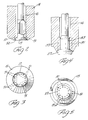
- Figure 2 is an enlarged sectional view of a portion of the charge delivery injector shown in Figure 1, showing internal flutes provided to generate an advantageous injector spray pattern.
- Figure 3 is an end view of the injector shown in Figure 2.
- Figure 4 is an enlarged sectional view similar to Figure 2 of another charge-delivery injector, showing alternative internal flutes provided to generate an advantageous injector spray pattern.
- Figure 5 is an end view of the injector shown in Figure 4.
- Figure 6 is a sectional view similar to Figure 1 of another fluid rail, showing an alternative air supply construction.
- Figure 7 is a sectional view, taken along line A-A of Figure 6, showing further details of the alternative air supply construction.
- Figure 8 is a sectional view similar to Figure 1 of yet another fluid rail, showing another alternative air supply construction.
- a fluid rail assembly has a fluid rail body 1 that supports fuel-metering injectors 2 and charge-delivery injectors 3 and associated electrical wiring and connectors 4 on an engine so each injector 3 may deliver a charge of fuel and air to its associated combustion chamber 5.
- Rail body 1 has a longitudinal air supply passage 6 aligned with the charge-delivery injectors 3.
- Passage 6 supplies air to a peripheral air supply passage channel 7 surrounding a housing 8 of solenoid coil assembly in each charge-delivery injector 3.
- Each channel 7 supplies air to a drilled air supply passage 9 containing a cup restrictor 10 that provides a calibrated orifice in passage 9.
- Each passage 9 supplies air to an air space 11 between an end of the associated fuel-metering injector 2 and body 1; each air space 11 is a wedge-shaped volume that is not occupied by a generally C-shaped elastomeric gasket 12 sandwiched between the end of the associated fuel-metering injector 2 and body 1.
- a drilled passage 13 connects each air space 11 to an aperture 14 in a nozzle 15 of the associated charge-delivery injector 3.
- aperture 14 opens into a region 16 surrounding a stem of its valve 17.
- Each injector 2 delivers metered fuel through its air space 11 and passage 13 to the aperture 14 of the associated charge-delivery injector 3, and through aperture 14 into the region 16 of injector 3.
- the solenoid coil of that charge-delivery injector 3 When the solenoid coil of that charge-delivery injector 3 is energized, its armature 18 is attracted against the bias of a return spring 19 to open valve 17. Air flow from passage 6 through channel 7, passage 9, air space 11, passage 13, aperture 14 and region 16 then delivers the fuel into the associated combustion chamber 5.
- the arrangement of supplying air flow into air space 11 using a circuitous route from the air supply passage 6 around the housing 8 of the solenoid coil assembly in each charge-delivery injector 3 provides two useful advantages in that the air flow supplied to air space 11 serves to cool the solenoid coil assembly before that air flow reaches air space 11, and in that the circuitous route of the air flow inhibits any tendency for back-flow of fuel from the fuel-metering injector 2 entering the air supply passage 6.
- each charge-delivery injector 3 By arranging for the solenoid coil assembly of each charge-delivery injector 3 to be positioned away from the direct flow path of the air-fuel charge supplied to the nozzle 15 through the air space 11, passage 13 and aperture 14, it is possible to keep the direct flow path of the air-fuel charge relatively short, thus avoiding any tendency of stratification occurring in the air-fuel charge before it reaches the nozzle 15.
- a secondary air flow path allows air flow upwardly through the clearance space between the outer diameter of each solenoid coil housing 8 and the rail body 1, radially inwardly through slots 23 in the base of the cover 21 into a cavity surrounding armature 18, downwardly through apertures 22 in the armature 18 into a cavity surrounding return spring 19, and downwardly through an annular orifice 20 between the valve stem and a top of nozzle 15 into region 16.
- the secondary air flow through orifice 20 is a small percentage of the air flow through the orifice in restrictor 10, but is sufficient to purge any fuel that may migrate into the secondary air flow path.
- each charge-delivery injector 3 can be installed and removed as a unit from the fluid delivery rail body 1.
- the solenoid coil assembly is secured to the nozzle 15 by press-fitting the nozzle 15 within a core 24 of the solenoid coil assembly.
- O-rings above and below passage 13 and aperture 14 seal against migration of fuel between nozzle 15 and fluid rail body 1 whilst permitting a sliding clearance between nozzle 15 and fluid rail body 1 that allows easy installation and removal of charge-delivery injector 3.
- a C-shaped washer 25 fits about the stem of valve 17 and rests on the top of nozzle 15 to provide a seat for return spring 19. Washer 25 has an inner diameter smaller than an upper end of the stem of valve 17 in order to capture valve 17 if an upper spring retainer 26 or an associated lock-ring 27 should break.
- Return spring 19 is calibrated by selecting a washer 25 of appropriate thickness, or by selecting an armature spring 28 of appropriate force. Travel of valve 17 is calibrated by adjusting set-screw 29 to position armature 18 at a desired distance above the top of the solenoid coil assembly, and employing nut 30 to lock set-screw 29 in place.
- Fuel is supplied to the fuel-metering injectors 2 by a longitudinal passage 31 that intersects the sockets for injectors 2. Fuel supply passage 31 is located above fuel-metering injectors 2 to permit easy exit of any vapor generated within the injectors or the injector sockets.
- the spacing between injectors 3 is not adjustable. This requires accurate control of the spacing between the holes in the cylinder heads that receive nozzles 15.
- the openings around nozzles 15 are larger than when the spacing between injectors 3 is adjustable, and a copper washer 32 and an O-ring 33 seal the opening about each nozzle 15. Washer 32 protects O-ring 33 against direct exposure to combustion chamber gases, and conducts heat away from the O-ring. Washer 32 has an interference fit on nozzle 15 and a clearance fit within the O-ring groove in the top of the head.
- each restrictor 10 inhibits back-flow of fuel into passage 9.
- the offset of passages 9 (about 90 degrees) from passage 6 inhibits back-flow of fuel into the air supply passage 6.
- fuel might be transferred from the fuel-metering injector 2 associated with one combustion chamber 5 to the charge-delivery injector 3 associated with another combustion chamber 5; in that event, fuel would be unevenly distributed amongst the combustion chambers 5.
- An auxiliary air reservoir 34 extends longitudinally through fluid rail body 1. Drilled passages 35 connect reservoir 34 to the air supply channels 7 that surround the solenoid coil assemblies of the charge-delivery injectors 3. In some applications, reservoir 34 may provide the sole air supply to channels 7, replacing air supply passage 6. Because reservoir 34 is connected to channels 7 through passages 35, and because passages 35 are offset about 180 degrees from passages 9, use of reservoir 34 as the sole air supply to channels 7 would further inhibit the possibility that fuel might be transferred from the fuel-metering injector 2 associated with one combustion chamber 5 to the charge-delivery injector 3 associated with another combustion chamber 5.
- each charge-delivery injector 3 has terminals 36 that exit at the bottom of the solenoid coil housing 8 and are connected by insulated wires to electrical connector 4. If desired, a terminal block 37 may be employed to connect the wires to terminals 36.
- a pin 38 carried by nozzle 15 is received in a slot in body 1 to assure that nozzle aperture 14 is aligned with body passage 13.
- nozzle 15 has internal flutes 51 spaced about the inside of the nozzle at the bottom of region 16. Flutes 51 promote filling in of the initially hollow spray pattern created by nozzle 15 and valve 17. That effect is believed to be due to the fact that tapered surfaces 52 of different lengths are exposed at the bottom of nozzle 15 when valve 17 is opened; the longer tapered surfaces between flutes 51 create a greater pressure drop than the shorter tapered surfaces at the ends of flutes 51; the different length surfaces 52 accordingly generate adjacent fuel streams of differing velocities that promote turbulence and mixing which, in turn, fills the hollow cone to produce a more uniform spray density.
- Flutes 51 are not exposed to the combustion products in combustion chamber 5 and accordingly are not readily susceptible to plugging. Moreover, the diverging surfaces on nozzle 15 and the head of valve 17, in combination with the lack of crevices on the outside of nozzle 15, discourages formation of deposits that could migrate.
- the stem of valve 17 is guided in nozzle 15 by the upper portion of nozzle 15 and a triangular portion of the valve stem near the head of valve 17.
- This construction assures good alignment of the head of valve 17 and the mating, sealing portions of surfaces 52 at the end of nozzle 15 to effect a tight seal therebetween.
- the stem of another valve 117 has a cylindrical boss 153 instead of the triangular portion of valve 17.
- Boss 153 is guided in the associated nozzle 115, and flutes 151 extend past boss 153 to deliver the fuel from the region 116 surrounding the stem of valve 117 within nozzle 115.
- Flutes 151 also promote filling in of spray pattern created by nozzle 115 and valve 117.
- Figures 6-7 illustrate another fluid rail body 201 in which an axially-extending groove 254 connects an air space 211 (at the end of fuel-metering injector 202) with a drilled air supply passage 209 that extends from an air supply channel 207 surrounding housing 208 of the solenoid coil assembly in a charge-delivery injector 203.
- air space 211 is the wedge-shaped volume that is not occupied by a generally C-shaped elastomeric gasket 212 sandwiched between the end of fuel-metering injector 202 and body 201.
- Other details of the Figure 2 fluid rail assembly are similar to the Figure 1 embodiment.
- Figure 8 illustrates yet another fluid rail body 301 in which an axially-extending groove 354 and a peripherally-extending groove 355 connect air space 311 (at the end of fuel-metering injector 302) with a drilled air supply passage 309 that extends from an air supply channel 307 surrounding housing 308 of the solenoid coil assembly in a charge-delivery injector 303.
- air space 311 is the wedge-shaped volume that is not occupied by a generally C-shaped elastomeric gasket 312 sandwiched between the end of fuel-metering injector 302 and body 301.
- Other details of the Figure 3 fluid rail assembly are similar to the other embodiments.
- Figures 6-8 further inhibit the back-flow of fuel to minimize the possibility that fuel might be transferred from the fuel-metering injector associated with one combustion chamber to the charge-delivery injector associated with another combustion chamber.
Description
- This invention relates to a fluid rail assembly adapted to deliver a fuel-air charge directly into an engine combustion chamber as specified in the preamble of claim 1, for example as disclosed in WO-A-88/07628.
- A fuel injector arrangement is disclosed in WO-A-86/00960 in which a solenoid coil assembly of the fuel injector is cooled by supplying air thereto by a circuitous channel surrounding a housing of the solenoid coil assembly.
- A fluid rail assembly according to the present invention is characterised by the features specified in the characterising portion of claim 1.
- Figure 1 is a transverse sectional view of a fluid rail mounted on an engine cylinder head, showing an injector for delivering a charge of fuel and air directly into one of the engine combustion chambers, and showing an injector for metering fuel to the charge-delivery injector.
- Figure 2 is an enlarged sectional view of a portion of the charge delivery injector shown in Figure 1, showing internal flutes provided to generate an advantageous injector spray pattern.
- Figure 3 is an end view of the injector shown in Figure 2.
- Figure 4 is an enlarged sectional view similar to Figure 2 of another charge-delivery injector, showing alternative internal flutes provided to generate an advantageous injector spray pattern.
- Figure 5 is an end view of the injector shown in Figure 4.
- Figure 6 is a sectional view similar to Figure 1 of another fluid rail, showing an alternative air supply construction.
- Figure 7 is a sectional view, taken along line A-A of Figure 6, showing further details of the alternative air supply construction.
- Figure 8 is a sectional view similar to Figure 1 of yet another fluid rail, showing another alternative air supply construction.
- Referring firstly to Figure 1, a fluid rail assembly has a fluid rail body 1 that supports fuel-metering injectors 2 and charge-
delivery injectors 3 and associated electrical wiring andconnectors 4 on an engine so eachinjector 3 may deliver a charge of fuel and air to its associatedcombustion chamber 5. - Rail body 1 has a longitudinal air supply passage 6 aligned with the charge-
delivery injectors 3. Passage 6 supplies air to a peripheral airsupply passage channel 7 surrounding a housing 8 of solenoid coil assembly in each charge-delivery injector 3. Eachchannel 7 supplies air to a drilledair supply passage 9 containing acup restrictor 10 that provides a calibrated orifice inpassage 9. Eachpassage 9 supplies air to an air space 11 between an end of the associated fuel-metering injector 2 and body 1; each air space 11 is a wedge-shaped volume that is not occupied by a generally C-shaped elastomeric gasket 12 sandwiched between the end of the associated fuel-metering injector 2 and body 1. A drilled passage 13 connects each air space 11 to an aperture 14 in a nozzle 15 of the associated charge-delivery injector 3. Within eachinjector 3, aperture 14 opens into aregion 16 surrounding a stem of itsvalve 17. - Each injector 2 delivers metered fuel through its air space 11 and passage 13 to the aperture 14 of the associated charge-
delivery injector 3, and through aperture 14 into theregion 16 ofinjector 3. When the solenoid coil of that charge-delivery injector 3 is energized, itsarmature 18 is attracted against the bias of a return spring 19 to openvalve 17. Air flow from passage 6 throughchannel 7,passage 9, air space 11, passage 13, aperture 14 andregion 16 then delivers the fuel into the associatedcombustion chamber 5. - The arrangement of supplying air flow into air space 11 using a circuitous route from the air supply passage 6 around the housing 8 of the solenoid coil assembly in each charge-
delivery injector 3 provides two useful advantages in that the air flow supplied to air space 11 serves to cool the solenoid coil assembly before that air flow reaches air space 11, and in that the circuitous route of the air flow inhibits any tendency for back-flow of fuel from the fuel-metering injector 2 entering the air supply passage 6. - By arranging for the solenoid coil assembly of each charge-
delivery injector 3 to be positioned away from the direct flow path of the air-fuel charge supplied to the nozzle 15 through the air space 11, passage 13 and aperture 14, it is possible to keep the direct flow path of the air-fuel charge relatively short, thus avoiding any tendency of stratification occurring in the air-fuel charge before it reaches the nozzle 15. - A secondary air flow path allows air flow upwardly through the clearance space between the outer diameter of each solenoid coil housing 8 and the rail body 1, radially inwardly through
slots 23 in the base of thecover 21 into acavity surrounding armature 18, downwardly throughapertures 22 in thearmature 18 into a cavity surrounding return spring 19, and downwardly through an annular orifice 20 between the valve stem and a top of nozzle 15 intoregion 16. The secondary air flow through orifice 20 is a small percentage of the air flow through the orifice inrestrictor 10, but is sufficient to purge any fuel that may migrate into the secondary air flow path. - For ease of assembly and service, each charge-
delivery injector 3 can be installed and removed as a unit from the fluid delivery rail body 1. The solenoid coil assembly is secured to the nozzle 15 by press-fitting the nozzle 15 within acore 24 of the solenoid coil assembly. O-rings above and below passage 13 and aperture 14 seal against migration of fuel between nozzle 15 and fluid rail body 1 whilst permitting a sliding clearance between nozzle 15 and fluid rail body 1 that allows easy installation and removal of charge-delivery injector 3. - Within each
injector 3, a C-shaped washer 25 fits about the stem ofvalve 17 and rests on the top of nozzle 15 to provide a seat for return spring 19.Washer 25 has an inner diameter smaller than an upper end of the stem ofvalve 17 in order to capturevalve 17 if anupper spring retainer 26 or an associated lock-ring 27 should break. - Return spring 19 is calibrated by selecting a
washer 25 of appropriate thickness, or by selecting anarmature spring 28 of appropriate force. Travel ofvalve 17 is calibrated by adjusting set-screw 29 to positionarmature 18 at a desired distance above the top of the solenoid coil assembly, and employing nut 30 to lock set-screw 29 in place. - Certain details of the structure at the top of charge-
delivery injectors 3 are set forth in US patent application 369 508 filed concurrently in the name of L. W. Weinand; the disclosure of that application is incorporated by reference. - The position of the fuel-metering injectors 2 relative to the charge-
delivery injectors 3 was selected to minimize the overall height of the fluid rail assembly. Fuel is supplied to the fuel-metering injectors 2 by a longitudinal passage 31 that intersects the sockets for injectors 2. Fuel supply passage 31 is located above fuel-metering injectors 2 to permit easy exit of any vapor generated within the injectors or the injector sockets. - Because the fluid rail body 1 is solid and the charge-
delivery injectors 3 are rigidly secured in the body 1, the spacing betweeninjectors 3 is not adjustable. This requires accurate control of the spacing between the holes in the cylinder heads that receive nozzles 15. To accommodate mounting of the fluid rail assembly on the engine without excessively tight machining tolerances, the openings around nozzles 15 are larger than when the spacing betweeninjectors 3 is adjustable, and acopper washer 32 and an O-ring 33 seal the opening about each nozzle 15. Washer 32 protects O-ring 33 against direct exposure to combustion chamber gases, and conducts heat away from the O-ring. Washer 32 has an interference fit on nozzle 15 and a clearance fit within the O-ring groove in the top of the head. Wheninjector 3 is installed, nozzle 15 deforms the inner portion ofwasher 32 into a conical shape, thereby effecting a tight seal. - The orifice in each
restrictor 10 inhibits back-flow of fuel intopassage 9. In addition, the offset of passages 9 (about 90 degrees) from passage 6 inhibits back-flow of fuel into the air supply passage 6. In the absence of provisions to inhibit such back-flow, fuel might be transferred from the fuel-metering injector 2 associated with onecombustion chamber 5 to the charge-delivery injector 3 associated with anothercombustion chamber 5; in that event, fuel would be unevenly distributed amongst thecombustion chambers 5. - An
auxiliary air reservoir 34 extends longitudinally through fluid rail body 1. Drilledpassages 35 connectreservoir 34 to theair supply channels 7 that surround the solenoid coil assemblies of the charge-delivery injectors 3. In some applications,reservoir 34 may provide the sole air supply tochannels 7, replacing air supply passage 6. Becausereservoir 34 is connected tochannels 7 throughpassages 35, and becausepassages 35 are offset about 180 degrees frompassages 9, use ofreservoir 34 as the sole air supply tochannels 7 would further inhibit the possibility that fuel might be transferred from the fuel-metering injector 2 associated with onecombustion chamber 5 to the charge-delivery injector 3 associated with anothercombustion chamber 5. - The solenoid coil assembly of each charge-
delivery injector 3 hasterminals 36 that exit at the bottom of the solenoid coil housing 8 and are connected by insulated wires toelectrical connector 4. If desired, aterminal block 37 may be employed to connect the wires toterminals 36. - A
pin 38 carried by nozzle 15 is received in a slot in body 1 to assure that nozzle aperture 14 is aligned with body passage 13. - As shown in Figures 2-3, nozzle 15 has
internal flutes 51 spaced about the inside of the nozzle at the bottom ofregion 16.Flutes 51 promote filling in of the initially hollow spray pattern created by nozzle 15 andvalve 17. That effect is believed to be due to the fact thattapered surfaces 52 of different lengths are exposed at the bottom of nozzle 15 whenvalve 17 is opened; the longer tapered surfaces betweenflutes 51 create a greater pressure drop than the shorter tapered surfaces at the ends offlutes 51; thedifferent length surfaces 52 accordingly generate adjacent fuel streams of differing velocities that promote turbulence and mixing which, in turn, fills the hollow cone to produce a more uniform spray density. -
Flutes 51 are not exposed to the combustion products incombustion chamber 5 and accordingly are not readily susceptible to plugging. Moreover, the diverging surfaces on nozzle 15 and the head ofvalve 17, in combination with the lack of crevices on the outside of nozzle 15, discourages formation of deposits that could migrate. - As shown in Figure 1, the stem of
valve 17 is guided in nozzle 15 by the upper portion of nozzle 15 and a triangular portion of the valve stem near the head ofvalve 17. This construction assures good alignment of the head ofvalve 17 and the mating, sealing portions ofsurfaces 52 at the end of nozzle 15 to effect a tight seal therebetween. - As shown in Figures 4-5, the stem of another
valve 117 has acylindrical boss 153 instead of the triangular portion ofvalve 17. Boss 153 is guided in the associatednozzle 115, andflutes 151 extend pastboss 153 to deliver the fuel from theregion 116 surrounding the stem ofvalve 117 withinnozzle 115.Flutes 151 also promote filling in of spray pattern created bynozzle 115 andvalve 117. - Figures 6-7 illustrate another
fluid rail body 201 in which an axially-extendinggroove 254 connects an air space 211 (at the end of fuel-metering injector 202) with a drilledair supply passage 209 that extends from anair supply channel 207surrounding housing 208 of the solenoid coil assembly in a charge-delivery injector 203. As in the Figure 1 embodiment,air space 211 is the wedge-shaped volume that is not occupied by a generally C-shapedelastomeric gasket 212 sandwiched between the end of fuel-metering injector 202 andbody 201. Other details of the Figure 2 fluid rail assembly are similar to the Figure 1 embodiment. - Figure 8 illustrates yet another
fluid rail body 301 in which an axially-extendinggroove 354 and a peripherally-extendinggroove 355 connect air space 311 (at the end of fuel-metering injector 302) with a drilledair supply passage 309 that extends from anair supply channel 307surrounding housing 308 of the solenoid coil assembly in a charge-delivery injector 303. As in the other embodiments,air space 311 is the wedge-shaped volume that is not occupied by a generally C-shaped elastomeric gasket 312 sandwiched between the end of fuel-metering injector 302 andbody 301. Other details of the Figure 3 fluid rail assembly are similar to the other embodiments. - The constructions of Figures 6-8 further inhibit the back-flow of fuel to minimize the possibility that fuel might be transferred from the fuel-metering injector associated with one combustion chamber to the charge-delivery injector associated with another combustion chamber.
Claims (2)
- A fluid rail assembly having a body (1;201;301) supporting a fuel-metering injector (2;202;302) and a charge-delivery injector (3;203;303), said body having a space (11;211;311) between the end of said fuel-metering injector (2;202;302) and the body, said charge-delivery injector (3;203;303) including a charge-delivery valve (17;117), a solenoid having an armature (18) for operating said valve (17;117), a valve stem connecting said valve (17;117) to said armature (18), and a nozzle (15;115) having an aperture (14), said nozzle (15;115) surrounding said valve stem; and said body including a first passage (13) extending directly from said space (11;211;311) to said aperture (14), and a second passage (9;209;309) for supplying air to said space (11;211;311) to assist delivery of fuel from said fuel-metering injector (2;202;302) to said nozzle (15;115), characterised in that said nozzle (15;115) is received in said body (1;201;301); said aperture (14) is a lateral aperture opening into a region (16;116) within said nozzle (15;115) about said valve stem below said solenoid; said fuel-metering injector (2;202;302) is adapted to deliver fuel through said space (11;211;311), said first passage (13) and said lateral aperture (14) to said region (16;116) within said nozzle (15;115); and air is supplied to said second passage (9;209;309) by a circuitous route which includes a channel (7;207;307) surrounding a housing (8;208;308) of the solenoid coil assembly.
- A fluid rail assembly according to claim 1, characterised in that said second passage (9) includes a cup restrictor (10) and the circuitous route of the air flow surrounding the housing (8;208;308) of the solenoid coil assembly is constructed to inhibit back-flow of fuel therethrough.
Applications Claiming Priority (2)
| Application Number | Priority Date | Filing Date | Title |
|---|---|---|---|
| US369510 | 1982-04-19 | ||
| US07/369,510 US5036824A (en) | 1989-06-21 | 1989-06-21 | Fuel injection |
Publications (2)
| Publication Number | Publication Date |
|---|---|
| EP0404345A1 EP0404345A1 (en) | 1990-12-27 |
| EP0404345B1 true EP0404345B1 (en) | 1993-01-20 |
Family
ID=23455787
Family Applications (1)
| Application Number | Title | Priority Date | Filing Date |
|---|---|---|---|
| EP90305498A Expired - Lifetime EP0404345B1 (en) | 1989-06-21 | 1990-05-21 | Fuel-injection assembly |
Country Status (4)
| Country | Link |
|---|---|
| US (1) | US5036824A (en) |
| EP (1) | EP0404345B1 (en) |
| JP (1) | JPH0343666A (en) |
| DE (1) | DE69000796T2 (en) |
Families Citing this family (13)
| Publication number | Priority date | Publication date | Assignee | Title |
|---|---|---|---|---|
| US5172865A (en) * | 1989-01-12 | 1992-12-22 | Toyota Jidosha Kabushiki Kaisha | Fuel supply device of an engine |
| JP2519979Y2 (en) * | 1990-02-14 | 1996-12-11 | トヨタ自動車株式会社 | Fuel injection device for internal combustion engine |
| US5170766A (en) * | 1992-01-16 | 1992-12-15 | Orbital Walbro Corporation | Fuel and air injection for multi-cylinder internal combustion engines |
| US5622155A (en) * | 1993-04-29 | 1997-04-22 | Orbital Engine Company (Australia) Pty. Limited | Fuel injected internal combustion engine |
| US5730369A (en) * | 1994-04-25 | 1998-03-24 | General Motors Corporation | Fuel injection |
| DE19523194C2 (en) * | 1995-06-26 | 1997-07-31 | Bernd Scheffel | Device for the intermittent spraying of a liquid |
| FR2760487B1 (en) * | 1997-03-07 | 1999-04-30 | Inst Francais Du Petrole | METHOD FOR CONTROLLING SELF-IGNITION IN A 4-STROKE ENGINE |
| US6161527A (en) * | 1999-02-11 | 2000-12-19 | Brunswick Corporation | Air assisted direct fuel injection system |
| DE10031733A1 (en) * | 2000-06-29 | 2002-01-17 | Bosch Gmbh Robert | Common Rail System |
| US6626160B2 (en) * | 2001-06-01 | 2003-09-30 | General Motors Corporation | Engine with air-assisted fuel injection and engine integrated air feed |
| EP1602825A1 (en) * | 2004-06-03 | 2005-12-07 | Delphi Technologies, Inc. | Fuel injector |
| EP1602824A1 (en) * | 2004-06-03 | 2005-12-07 | Delphi Technologies, Inc. | Fuel injector |
| CN114198233A (en) * | 2021-12-16 | 2022-03-18 | 北京理工大学 | Integrated vertically-arranged compact air-assisted injection system structure |
Family Cites Families (13)
| Publication number | Priority date | Publication date | Assignee | Title |
|---|---|---|---|---|
| US4082224A (en) * | 1976-10-07 | 1978-04-04 | Caterpillar Tractor Co. | Fuel injection nozzle |
| PH25880A (en) * | 1983-08-05 | 1991-12-02 | Orbital Eng Pty | Fuel injection method and apparatus |
| IN165341B (en) * | 1984-08-01 | 1989-09-23 | Orbital Eng Pty | |
| CA1289429C (en) * | 1985-07-19 | 1991-09-24 | Roy Stanley Brooks | Nozzles for fuel injection systems |
| CA1279798C (en) * | 1985-07-19 | 1991-02-05 | Peter William Ragg | Fuel injection |
| BR8606918A (en) * | 1985-10-11 | 1987-11-03 | Orbital Eng Pty | IMPROVEMENTS RELATING TO FUEL DOSING |
| GB2182978B (en) * | 1985-11-13 | 1989-10-04 | Orbital Eng Pty | Improvements relating to nozzles for in-cylinder fuel injection systems |
| GB2193252B (en) * | 1986-08-01 | 1991-02-06 | Orbital Eng Pty | Improvements relating to the injection of fuel to an engine |
| MX169738B (en) * | 1987-04-03 | 1993-07-22 | Orbital Eng Pty | FUEL INJECTION SYSTEM FOR AN INTERNAL COMBUSTION ENGINE OF MULTIPLE CYLINDERS |
| US4771754A (en) * | 1987-05-04 | 1988-09-20 | General Motors Corporation | Pneumatic direct cylinder fuel injection system |
| US4926806A (en) * | 1988-02-25 | 1990-05-22 | Orbital Engine Co., Proprietary Limited | Two-fluid fuel injected engines |
| US4962745A (en) * | 1988-10-04 | 1990-10-16 | Toyota Jidosha Kabushiki Kaisha | Fuel supply device of an engine |
| US4934346A (en) * | 1989-07-10 | 1990-06-19 | Outboard Marine Corporation | Sidewall cylinder entrapment valve for internal combustion chamber |
-
1989
- 1989-06-21 US US07/369,510 patent/US5036824A/en not_active Expired - Fee Related
-
1990
- 1990-05-21 EP EP90305498A patent/EP0404345B1/en not_active Expired - Lifetime
- 1990-05-21 DE DE9090305498T patent/DE69000796T2/en not_active Expired - Fee Related
- 1990-06-21 JP JP2164000A patent/JPH0343666A/en active Pending
Also Published As
| Publication number | Publication date |
|---|---|
| US5036824A (en) | 1991-08-06 |
| EP0404345A1 (en) | 1990-12-27 |
| DE69000796D1 (en) | 1993-03-04 |
| DE69000796T2 (en) | 1993-05-06 |
| JPH0343666A (en) | 1991-02-25 |
Similar Documents
| Publication | Publication Date | Title |
|---|---|---|
| EP0404345B1 (en) | Fuel-injection assembly | |
| KR950011329B1 (en) | A fuel injertion system for a multi-cylinder engine | |
| US5715788A (en) | Integrated fuel injector and ignitor assembly | |
| US6260537B1 (en) | Side feed fuel injector and integrated fuel rail/intake manifold | |
| US5934252A (en) | Fuel injection system | |
| US4972996A (en) | Dual lift electromagnetic fuel injector | |
| US5531202A (en) | Fuel rail assembly having internal electrical connectors | |
| US20040021014A1 (en) | Fuel injection valve | |
| JPS62168961A (en) | Nozzle for fuel injection system in cylinder | |
| US6520154B2 (en) | Side feed fuel injector and integrated fuel rail/intake manifold | |
| US6257509B1 (en) | Fuel injector | |
| US5080070A (en) | Hydraulic circuit of a fuel injection system | |
| US5101800A (en) | Fuel injection | |
| US6935582B2 (en) | Fuel injector | |
| JPH0842429A (en) | Fuel injection valve | |
| US5730369A (en) | Fuel injection | |
| US6497218B2 (en) | Fuel injector module | |
| US6598804B2 (en) | Fuel injector | |
| EP0610932B1 (en) | Fuel supply system for internal combustion engine | |
| US6626160B2 (en) | Engine with air-assisted fuel injection and engine integrated air feed | |
| EP0718492A1 (en) | Fuel injector | |
| JP2555626B2 (en) | Fuel injection device for internal combustion engine | |
| AU621820B2 (en) | A fuel injection system for a multi-cylinder engine | |
| JP2759993B2 (en) | Fuel injection valve | |
| SU1312231A1 (en) | Diesel engine fuel injector |
Legal Events
| Date | Code | Title | Description |
|---|---|---|---|
| PUAI | Public reference made under article 153(3) epc to a published international application that has entered the european phase |
Free format text: ORIGINAL CODE: 0009012 |
|
| AK | Designated contracting states |
Kind code of ref document: A1 Designated state(s): DE FR GB IT |
|
| 17P | Request for examination filed |
Effective date: 19910128 |
|
| 17Q | First examination report despatched |
Effective date: 19910930 |
|
| ITF | It: translation for a ep patent filed |
Owner name: BARZANO' E ZANARDO ROMA S.P.A. |
|
| GRAA | (expected) grant |
Free format text: ORIGINAL CODE: 0009210 |
|
| AK | Designated contracting states |
Kind code of ref document: B1 Designated state(s): DE FR GB IT |
|
| REF | Corresponds to: |
Ref document number: 69000796 Country of ref document: DE Date of ref document: 19930304 |
|
| ET | Fr: translation filed | ||
| PLBE | No opposition filed within time limit |
Free format text: ORIGINAL CODE: 0009261 |
|
| STAA | Information on the status of an ep patent application or granted ep patent |
Free format text: STATUS: NO OPPOSITION FILED WITHIN TIME LIMIT |
|
| 26N | No opposition filed | ||
| PGFP | Annual fee paid to national office [announced via postgrant information from national office to epo] |
Ref country code: GB Payment date: 19940422 Year of fee payment: 5 |
|
| PGFP | Annual fee paid to national office [announced via postgrant information from national office to epo] |
Ref country code: FR Payment date: 19940530 Year of fee payment: 5 |
|
| PGFP | Annual fee paid to national office [announced via postgrant information from national office to epo] |
Ref country code: DE Payment date: 19940712 Year of fee payment: 5 |
|
| PG25 | Lapsed in a contracting state [announced via postgrant information from national office to epo] |
Ref country code: GB Effective date: 19950521 |
|
| ITTA | It: last paid annual fee | ||
| GBPC | Gb: european patent ceased through non-payment of renewal fee |
Effective date: 19950521 |
|
| PG25 | Lapsed in a contracting state [announced via postgrant information from national office to epo] |
Ref country code: DE Effective date: 19960201 |
|
| PG25 | Lapsed in a contracting state [announced via postgrant information from national office to epo] |
Ref country code: FR Effective date: 19960229 |
|
| REG | Reference to a national code |
Ref country code: FR Ref legal event code: ST |
|
| REG | Reference to a national code |
Ref country code: FR Ref legal event code: ST |
|
| PG25 | Lapsed in a contracting state [announced via postgrant information from national office to epo] |
Ref country code: IT Free format text: LAPSE BECAUSE OF NON-PAYMENT OF DUE FEES;WARNING: LAPSES OF ITALIAN PATENTS WITH EFFECTIVE DATE BEFORE 2007 MAY HAVE OCCURRED AT ANY TIME BEFORE 2007. THE CORRECT EFFECTIVE DATE MAY BE DIFFERENT FROM THE ONE RECORDED. Effective date: 20050521 |