EP0610932B1 - Fuel supply system for internal combustion engine - Google Patents
Fuel supply system for internal combustion engine Download PDFInfo
- Publication number
- EP0610932B1 EP0610932B1 EP94102064A EP94102064A EP0610932B1 EP 0610932 B1 EP0610932 B1 EP 0610932B1 EP 94102064 A EP94102064 A EP 94102064A EP 94102064 A EP94102064 A EP 94102064A EP 0610932 B1 EP0610932 B1 EP 0610932B1
- Authority
- EP
- European Patent Office
- Prior art keywords
- fuel
- air
- holes
- supply system
- jets
- Prior art date
- Legal status (The legal status is an assumption and is not a legal conclusion. Google has not performed a legal analysis and makes no representation as to the accuracy of the status listed.)
- Expired - Lifetime
Links
- 239000000446 fuel Substances 0.000 title claims description 201
- 238000002485 combustion reaction Methods 0.000 title claims description 30
- 239000007921 spray Substances 0.000 claims description 27
- 238000002347 injection Methods 0.000 description 47
- 239000007924 injection Substances 0.000 description 47
- 238000000889 atomisation Methods 0.000 description 10
- 238000003892 spreading Methods 0.000 description 9
- 230000000694 effects Effects 0.000 description 6
- XEEYBQQBJWHFJM-UHFFFAOYSA-N Iron Chemical group [Fe] XEEYBQQBJWHFJM-UHFFFAOYSA-N 0.000 description 4
- 239000000203 mixture Substances 0.000 description 4
- 238000003466 welding Methods 0.000 description 4
- 238000009826 distribution Methods 0.000 description 3
- 238000011144 upstream manufacturing Methods 0.000 description 3
- 239000004734 Polyphenylene sulfide Substances 0.000 description 2
- 238000002844 melting Methods 0.000 description 2
- 230000008018 melting Effects 0.000 description 2
- 238000000034 method Methods 0.000 description 2
- 230000000149 penetrating effect Effects 0.000 description 2
- 229920000069 polyphenylene sulfide Polymers 0.000 description 2
- 238000010298 pulverizing process Methods 0.000 description 2
- 238000000926 separation method Methods 0.000 description 2
- 125000006850 spacer group Chemical group 0.000 description 2
- 239000004677 Nylon Substances 0.000 description 1
- 229930182556 Polyacetal Natural products 0.000 description 1
- 230000002411 adverse Effects 0.000 description 1
- 238000010586 diagram Methods 0.000 description 1
- 238000009792 diffusion process Methods 0.000 description 1
- 239000011521 glass Substances 0.000 description 1
- 238000001746 injection moulding Methods 0.000 description 1
- 238000004519 manufacturing process Methods 0.000 description 1
- 239000000463 material Substances 0.000 description 1
- 229920001778 nylon Polymers 0.000 description 1
- 229920006324 polyoxymethylene Polymers 0.000 description 1
- 238000003825 pressing Methods 0.000 description 1
- 239000011347 resin Substances 0.000 description 1
- 229920005989 resin Polymers 0.000 description 1
- 238000009718 spray deposition Methods 0.000 description 1
- 238000005507 spraying Methods 0.000 description 1
- 230000002195 synergetic effect Effects 0.000 description 1
Images


Classifications
-
- F—MECHANICAL ENGINEERING; LIGHTING; HEATING; WEAPONS; BLASTING
- F02—COMBUSTION ENGINES; HOT-GAS OR COMBUSTION-PRODUCT ENGINE PLANTS
- F02M—SUPPLYING COMBUSTION ENGINES IN GENERAL WITH COMBUSTIBLE MIXTURES OR CONSTITUENTS THEREOF
- F02M69/00—Low-pressure fuel-injection apparatus ; Apparatus with both continuous and intermittent injection; Apparatus injecting different types of fuel
- F02M69/04—Injectors peculiar thereto
- F02M69/047—Injectors peculiar thereto injectors with air chambers, e.g. communicating with atmosphere for aerating the nozzles
-
- F—MECHANICAL ENGINEERING; LIGHTING; HEATING; WEAPONS; BLASTING
- F02—COMBUSTION ENGINES; HOT-GAS OR COMBUSTION-PRODUCT ENGINE PLANTS
- F02M—SUPPLYING COMBUSTION ENGINES IN GENERAL WITH COMBUSTIBLE MIXTURES OR CONSTITUENTS THEREOF
- F02M37/00—Apparatus or systems for feeding liquid fuel from storage containers to carburettors or fuel-injection apparatus; Arrangements for purifying liquid fuel specially adapted for, or arranged on, internal-combustion engines
-
- F—MECHANICAL ENGINEERING; LIGHTING; HEATING; WEAPONS; BLASTING
- F02—COMBUSTION ENGINES; HOT-GAS OR COMBUSTION-PRODUCT ENGINE PLANTS
- F02M—SUPPLYING COMBUSTION ENGINES IN GENERAL WITH COMBUSTIBLE MIXTURES OR CONSTITUENTS THEREOF
- F02M69/00—Low-pressure fuel-injection apparatus ; Apparatus with both continuous and intermittent injection; Apparatus injecting different types of fuel
- F02M69/04—Injectors peculiar thereto
- F02M69/042—Positioning of injectors with respect to engine, e.g. in the air intake conduit
- F02M69/044—Positioning of injectors with respect to engine, e.g. in the air intake conduit for injecting into the intake conduit downstream of an air throttle valve
-
- F—MECHANICAL ENGINEERING; LIGHTING; HEATING; WEAPONS; BLASTING
- F02—COMBUSTION ENGINES; HOT-GAS OR COMBUSTION-PRODUCT ENGINE PLANTS
- F02M—SUPPLYING COMBUSTION ENGINES IN GENERAL WITH COMBUSTIBLE MIXTURES OR CONSTITUENTS THEREOF
- F02M69/00—Low-pressure fuel-injection apparatus ; Apparatus with both continuous and intermittent injection; Apparatus injecting different types of fuel
- F02M69/08—Low-pressure fuel-injection apparatus ; Apparatus with both continuous and intermittent injection; Apparatus injecting different types of fuel characterised by the fuel being carried by compressed air into main stream of combustion-air
Definitions
- This invention relates to a fuel supply system for an internal combustion engine according to the preamble of the patent claim 1.
- a fuel supply system in which a fuel injection valve is provided in an intake pipe on the upstream side of an intake port of an internal combustion engine, and an air-fuel mixture in which a fuel from the fuel injection valve and air are preliminarily mixed is supplied to the engine. Pulverization or atomization of the injected fuel and the atomized state of the fuel are controlled so as to improve combustion characteristics.
- a combustion chamber is provided with two intake valves for the purpose of achieving high-speed and high-power performance of an internal combustion engine, it is necessary to evenly distribute fuel from a fuel injection valve in the vicinity of an intake port to the two intake valves.
- a fuel injection valve has been proposed which is designed so as to form bundles of fuel spray by separating fuel flow in two directions from the fuel injection valve (Japanese Patent Unexamined Publication No. 4-50472).
- fuel is jetted from two injection holes so that two fuel flows are evenly directed toward the two intake valves. Simultaneously, air and fuel are caused to impinge against and mix with each other so that injected fuel is finely pulverized.
- a main air hole is provided at a position between two injection holes for separating a fuel spray in the fuel injection system disclosed in Japanese Patent Unexamined Publication No.4-50472, it is necessary to supply air through the main air hole at a very high flow rate in order to separate a fuel spray in two directions.
- fuel jets from the two injection holes cannot be separated suitably unless the area of a sub air hole is made smaller than that of the main hole so that the area ratio (main air hole area)/(sub air hole area) is about 6.
- the maximum air flow rate in view of idling, at which air can be introduced into the fuel injection valve, for a reason relating to the internal combustion engine system.
- the maximum air flow rate is limited to 1.3 m 3 /h. Therefore, if the main air hole and the fuel injection holes are spaced apart from each other as in this fuel injection system, the air flow cannot be utilized effectively and it is difficult to suitably pulverize or atomize fuel.
- the present invention proceeds from a fuel supply means for a combustion machine as is described in the document DE-42 118 896.
- This fuel supply means comprises an injection nozzle having two fuel injection openings, each of which injects a fuel jet directed to an intake valve. Further, according to the introductory part of the specification of this reference, assist air channels are arranged around the fuel outlet openings which can be selectively opened for swirling the fuel. In this connection, it can clearly be gathered from the introductory part of the specification that in the event that assist air is added to the fuel jets, a swirl is produced, so that the originally individual, bundled fuel jets are swirled so as to form one single spray jet.
- the slit-like air holes are arranged in the sleeve nozzle on opposite sides and in the vicinity of the fuel jets and extend in a direction in which the flow separating holes are aligned, wherein opposite slit ends of the air slits are closed in the vicinity of the outer wall of the sleeve nozzle so that assist air is jetted in a band-like manner such that the assist air jets sandwich the fuel jets therebetween.
- fuel jet from the fuel injection hole of the fuel injection valve is jetted through the fuel flow separation holes of the sleeve nozzle while being separated into different flows or jets.
- the fuel stomization is achieved by the band-like air flow from the air holes close to the injection port means while keeping fuel flow direction. Therefore, fuel sprays blown toward, for example, two intake valves such as those shown in Fig. 3 are sprayed while being separated in two directions toward the respective intake valves.
- the amount of fuel impinging directly against walls forming the two intake ports is reduced and the amount of atomized sprayed fuel directly entering a combustion chamber from the intake ports is therefore increased, thereby improving combustion characteristics.
- intake valves 101 and 102 are mounted in an internal combustion engine 100 at intake ports 112 and 113 which open to a combustion chamber 11.
- the intake valves 101 and 102 are operated to open and close the openings of the intake ports 112 and 113.
- a wall 114 is formed between the intake ports 112 and 113 to separate these ports.
- An intake pipe 62 has an intake passage 61 which communicates with the intake port 112.
- An intake throttle valve 63 for opening and closing the intake passage 61 is turnably mounted in the intake pipe 62.
- a fuel injection valve 1 is mounted in an outer wall of the intake pipe 62 on the downstream side of the intake throttle valve 63 so as to spray fuel toward each of the intake valves 101 and 102.
- an air supply passage 65 is provided which communicates the intake passage 61 on the upstream side of the intake throttle valve 63 with an assist air passage of the fuel injection valve 1 to be described later.
- An electromagnetic valve 66 is provided in an intermediate portion of the air supply passage 65 to adjust the rate at which assist air is supplied to the fuel injection valve 1.
- the fuel injection valve 1 which is operated electromagnetically is mounted in a delivery pipe 2 shown in Fig. 2.
- the delivery pipe 2 supplies fuel to each of cylinders of the internal combustion engine.
- the fuel injection valve 1 has a housing 3 having in the form of a stepped cylinder.
- An electromagnetic coil 5 is disposed in a large-diameter portion of the housing 3 to be wound around a spool 4.
- a cylindrical iron core 6 is provided to extend through the spool 4 from a position above the spool 4.
- An adjusting pipe 7 is provided in the iron core 6 slidably in an axial direction.
- a nozzle body 10 is fitted onto and fixed to a small-diameter portion of the housing 3 with a spacer 9 interposed therebetween.
- a fuel injection port 12 is formed in an end surface of a downwardly projecting portion of the nozzle body 10.
- a needle valve 14 is slidably inserted in the nozzle body 10 from the upper opening of the same.
- a pintle 16 is formed at a tip end of the needle valve 14. The pintle 16 extends through the fuel injection port 12 with a gap therebetween.
- a stopper 18 is formed substantially at a center of the needle valve 14 so as to face the spacer 9.
- a movable core 20 facing the iron core 6 is connected to an upper end portion of the needle valve 14.
- the movable core 20 is urged downward by a coil spring 22 disposed between the iron core 6 and the adjusting pipe 7.
- a split type resin sleeve 24 is provided to surround the end portion of the nozzle body 10.
- the sleeve 24 is constituted by an inner sleeve nozzle 30 and an outer cover nozzle 31.
- the sleeve nozzle 30 and the cover nozzle 31 which form the sleeve 24 are made of a material such as 6-6 nylon (containing 30 wt% glass), polyacetal, or PPS (polyphenylene sulfide).
- the inner sleeve nozzle 30 has two fuel flow separating holes 32 and 33. Each of the fuel flow separating holes 32 and 33 has a generally conical shape such that the sectional area is reduced in the downstream direction of a fuel jet.
- the inner sleeve nozzle 30 has a tapered surface 30a and an annular stepped portion 30b in its outer wall surface.
- the outer cover nozzle 31 has holes, e.g., six holes 44 and 45 (holes 45 not shown) for forming an air inlet to extend from its inner surface to its outer surface.
- the sectional area of each of the holes 44 and 45 suffices to be equal to or greater than the sectional area of a passage defined between a channel 34 or 35 (channel 35 not shown) and an inner surface of the cover nozzle 31.
- a diffusion section 50 for guiding sprays of atomized fuel agitated by assist air
- a skirt portion 49 for limiting the divergence of fuel spray angles
- a chamfered portion 51 for positioning at the time of automatic assembly. Gaps A and B shown in Fig.
- a passage inside the delivery pipe 2 through which fuel introduced through the fuel inlet flows is formed between a first O-ring 58 and a second O-ring 59. Air introduced via an air passage 2a formed in the delivery pipe 2 is sealed in a diametral direction between the second O-ring 59 and a third O-ring 60.
- the fuel flow separating hole 33 is formed to have a tapered cylindrical shape to be reduced in diameter toward its downstream end.
- a pair of air holes 62 and 63 in the form of straight slits having a constant width are opened in a lower end surface 30c of the sleeve nozzle 30 on the opposite sides of the opening ends of the fuel flow separating holes 32 and 33.
- the air slits 62 and 63 are formed in the vicinity of the opening ends of the fuel flow separating holes 32 and 33 on the lower end surface 30c of the sleeve nozzle 30.
- Opposite slit ends 62a, 62b, 63a, and 63b of the straight air slits 62 and 63 are closed in the vicinity of the sleeve nozzle outer wall.
- Intermediate air passages 68 and 69 (passage 68 is not shown) for supply of air, leading to the opening ends of the air slits 62 and 63 extend obliquely from the air passages constituted by channels 34.
- Assist air flowing out of the air slits 62 and 63 has a flow rate distribution shown in Fig. 6. That is, the air flow rate is increased about a central portion of each of the air slits 62 and 63.
- the length of the air slits 62 and 63 is selected to be longer than the distance between the centers of the two fuel flow separating holes 32 and 33 if no sub air hole is provided. This is because the effect of separating fuel in two directions is not adequate if the length of the air slits 62 and 63 is smaller than the distance between the centers of the two fuel flow separating holes 32 and 33.
- Fig. 7 shows directions of fuel and assist air flows in a cross section taken along the line VII - VII of Fig. 1
- Fig. 8 shows directions of fuel and assist air flows in a cross section taken along the line VIII - VIII of Fig. 1.
- jets of fuel from the fuel flow separating holes 32 and 33 interfere with assist air flows from the air slits 62 and 63 inside the skirt portion 49, thereby forming a flat sectoral flow surface F. That is, by forming flat jets of assist air, fuel jets flowing from the fuel flow separating holes 32 and 33 are atomized while being separated from each other and caused to flow independently in two directions. Fuel-air mixture flows in two directions are thereby supplied as sprays while being separated from each other and being independently directed toward the intake valves on the opposite sides of the wall 114 shown in Fig. 3. Therefore, fuel sprays thereby supplied to the combustion chamber 11 has such good characteristics that fuel can be completely combusted with air.
- a wall or curtain of an assist air flow is formed by assist air flows from the air slits 62 and 63 so that sprays of atomized fuel can be positively separated in two directions.
- the assist air flow wall is particularly strong at a central portion, so that the flows in two directions can be separated more positively.
- atomization of sprayed fuel can be suitably maintained or promoted by relatively weak assist air flows from end portions of the air holes 62 and 63.
- the assist air jet angle ⁇ is excessively large, the fuel spray angle is so small that the penetrating force is insufficient. If the assist air jet angle ⁇ is excessively small, fuel cannot be adequately separated in two directions and cannot be sufficiently atomized. Therefore, the angle of inclination of the air passage 69 is selected in view of the suitable range of the assist air jet angle.
- the cover nozzle 31 and the sleeve nozzle 30 are formed by injection molding.
- the cover nozzle 31 and the sleeve nozzle 30 are joined integrally with each other by inserting the sleeve nozzle 30 into the cover nozzle 31 and fusing these nozzles.
- the sleeve nozzle 30 is inserted through an opening 31c of the cover nozzle 31.
- the sleeve nozzle 30 is inserted into the cover nozzle 31, and the stepped portion 30b and a stepped portion 31b are pressed against each other by pressing the cover nozzle 31 and the sleeve nozzle 30.
- the stepped portion 30b is melted by ultrasonic wave vibration.
- a burr caused by ultrasonic waves enters a burr receiving space 53, so that any adverse influence upon the O-ring 60 shown in Fig. 2 can be avoided.
- the stepped portion 30b is being melted by ultrasonic waves, the sleeve nozzle 30 is press-fitted into the cover nozzle 31. The application of ultrasonic waves is stopped when the tapered surface 30a is brought into abutment against the cover nozzle 31.
- the sleeve nozzle 30 and the fuel injection valve 1 are assembled in such a manner that the sleeve nozzle 30 is press-fitted onto the outer circumference of the nozzle body 10 of the fuel injection valve 1 while a groove 10a and a projecting portion 30c are snap-fitted to prevent coming-off. Also at this time, the nozzle body 10 and the sleeve nozzle 30 are positioned in the direction of their relative rotation.
- fuel introduced through the fuel inlet passes through a metering section and is jetted through the fuel injection holes 12, and the fuel jet is separated in two directions by the fuel flow separating holes 32 and 33 of the sleeve nozzle 30 and is immediately separated and atomized by air jets jetted through the passage 69 and air slits 62 and 63 to be directed to the two intake valves while being maintained in specified directions.
- the above-described embodiment has fuel flow separating holes for separating a fuel flow in two directions since there are provided two intake valves.
- a fuel supply system can be designed easily to distribute fuel in three or more directions as desired.
- sub air holes 74, 75, 76, and 77 are formed while main air holes 72 and 73 in the form of straight slits are formed to be smaller in length in lengthwise directions.
- the sub air holes 74 to 77 are formed as grooves in outer wall portions of the sleeve nozzle 30.
- the main air holes 72 and 73 serve mainly to improve the function of separating a fuel spray in two directions, and the sub air holes 74 to 77 serve mainly to promote atomization of fuel.
- main air holes 82 and 83 in the form of curved slits are provided in place of the main air holes 62 and 63 of straight slits in the first embodiment shown in Fig. 1.
- the main air holes 82 and 83 are opened in the lower end surface of the sleeve nozzle 30 in positions close to the fuel flow separating holes 32 and 33 with their central portions curved toward the center of the sleeve.
- main air holes 86 and 87 in the form of slits curved oppositely are provided in place of the curved main air slits 82 and 83 shown in Fig. 10.
- the main air holes 86 and 87 are opened in the lower end surface 30c of the sleeve nozzle 30 in positions close to the fuel flow separating holes 32 and 33 with their central portions curved in a centrifugal direction of the sleeve.
- main air holes 90 and 91 and sub air holes 92 and 93 are formed in place of the straight air slits 62 and 63 shown in Fig. 1.
- the main air holes 90 and 91 are formed to be smaller in length in lengthwise directions, and the sub air holes 92 and 93 are formed as grooves in outer wall portions of the sleeve nozzle 30.
- four sub air holes 94, 95, 96, and 97 are formed in place of the curved sub air slits 92 and 93 shown in Fig. 14 to be recessed in the cover nozzle 31.
- a fuel jet jetted from the single fuel injection hole 12 is distributed into fuel jets flowing in two directions through the fuel flow separating holes 32 and 33, and two assist air jets spreading two-dimensionally are caused to impinge against the distributed fuel jets from the opposite sides of the fuel jets in such a manner that the fuel jets are sandwiched between the assist air jets, thereby forming sprays of atomized fuel extending in two directions. Therefore, it is possible to suppress excessive spreading of the fuel sprays while improving the atomization of fuel and to maintain suitable two spraying directions.
- the above-described embodiments may be modified in such a manner that a plurality of fuel injection holes are provided to form fuel sprays flowing in two or more directions.
- a thin orifice plate is mounted in place of the fuel injection port 12, and a plurality of fuel injection ports are formed in this orifice plate.
- four fuel injection ports having a fuel metering function are formed and two of these injection ports are directed together toward one of the intake valves while the other two injection ports are directed toward the other intake valve.
- the injector main body including the orifice plate serves as a fuel spray forming member.
- substantially large holes are formed in place of the fuel flow separating holes 32 and 33, and fuel jets jetted from the orifice plate and flowing in two direction air supplied with dimensionally-spreading assist air jets on the opposite sides of the fuel jets. Accordingly, the atomization of fuel is promoted by a synergic effect of the fuel atomizing effect of the fuel injection ports in the orifice plate and the fuel atomizing effect of assist air. Also, the direction of fuel jetting can be suitably maintained by the two-dimensionally-spreading assist air jets.
- Positions at which assist air jet flows impinge against the fuel jets must be selected according to the spray configuration. If the fuel jet outlets and the assist air jet outlets are close to each other, the direction of the assist air jets may be parallel to the fuel jets.
- two-dimensionally-flowing assist air jets may be applied to a single fuel jet flow, whereby spreading of a single fuel spray can be suppressed while the atomization of fuel is promoted.
- air holes in the form of slits extending straight or curvedly are formed on the opposite sides of injection hole openings, and assist air flows are jetted two-dimensionally from these air slits to impinge against fuel jets.
- This arrangement ensures that fuel jetted through the flow separating holes can be suitably atomized while being maintained in a state of being separated from each other and being caused to flow independently in two directions.
- flat flow surfaces can be formed because air slits are provided on the opposite sides of the two flow separating holes, and, by these flat flow surfaces, two fuel jets from the two flow separating holes can be suitably atomized and caused to flow constantly in the desired jetting directions without being mixed with each other. Moreover, spreading of the atomized fuel sprays in a vertical direction can be suppressed by the flat flow surfaces.
- the air slits due to the effect of jetting two-dimensionally-spreading assist air flows through the air slits, spreading of atomized fuel sprays is suppressed in a direction (illustrated as a vertical direction) perpendicular to the direction of arrangement of the two flow separating holes (illustrated as a horizontal direction), so that an amount of fuel attached to the intake passage wall is reduced. Also, the air slits are formed to be sufficiently long, whereby spreading of the atomized fuel sprays is suppressed in the direction of arrangement of the two flow separating holes (illustrated as a horizontal direction) without providing any sub air hole.
- the present invention makes it possible to obtain good characteristics of forming sprays of fuel jetted through a plurality of injection ports of a fuel injection valve with respect to separation of sprays in different directions, atomization, jetting angles and penetrating force.
- Fuel jetted through the injection ports of the fuel injection valve is jetted in separate jets from a plurality of fuel flow separating holes (32, 33) of a sleeve nozzle (30).
- band-like assist air flows are jetted in a two-dimensional manner from slit-like air holes (62, 63) opened on the opposite sides of the fuel flow separating holes (32, 33) to impinge obliquely against the jetted fuel.
- Atomization of fuel jetted through the plurality of fuel flow separating holes (32, 33) is thereby promoted and fuel sprays are accurately separated and supplied independently in two directions toward two intake valves while the directions of jets from the injection ports of the fuel injection valve are maintained, thus injecting and supplying fuel.
- an amount of fuel impinging directly against walls which separates and forms two intake ports is reduced and an amount of atomized sprayed fuel directly entering a combustion chamber from the intake ports is therefore increased, thereby improving combustion characteristics.
Description
- This invention relates to a fuel supply system for an internal combustion engine according to the preamble of the patent claim 1.
- A fuel supply system is known in which a fuel injection valve is provided in an intake pipe on the upstream side of an intake port of an internal combustion engine, and an air-fuel mixture in which a fuel from the fuel injection valve and air are preliminarily mixed is supplied to the engine. Pulverization or atomization of the injected fuel and the atomized state of the fuel are controlled so as to improve combustion characteristics.
- If a combustion chamber is provided with two intake valves for the purpose of achieving high-speed and high-power performance of an internal combustion engine, it is necessary to evenly distribute fuel from a fuel injection valve in the vicinity of an intake port to the two intake valves. To achieve this effect, a fuel injection valve has been proposed which is designed so as to form bundles of fuel spray by separating fuel flow in two directions from the fuel injection valve (Japanese Patent Unexamined Publication No. 4-50472). In this case, fuel is jetted from two injection holes so that two fuel flows are evenly directed toward the two intake valves. Simultaneously, air and fuel are caused to impinge against and mix with each other so that injected fuel is finely pulverized.
- For example, in the case where, as shown in Fig. 3, fuel is to be jetted from a fuel injection valve 1 toward two
intake valves - The inventors of the present invention has experimentally found the following fact. If a main air hole is provided at a position between two injection holes for separating a fuel spray in the fuel injection system disclosed in Japanese Patent Unexamined Publication No.4-50472, it is necessary to supply air through the main air hole at a very high flow rate in order to separate a fuel spray in two directions. For example, fuel jets from the two injection holes cannot be separated suitably unless the area of a sub air hole is made smaller than that of the main hole so that the area ratio (main air hole area)/(sub air hole area) is about 6. with respect to non-supercharging introduction of air from the upstream side of an intake throttle valve to a fuel injection valve in an internal combustion engine, there is a limit to the maximum air flow rate in view of idling, at which air can be introduced into the fuel injection valve, for a reason relating to the internal combustion engine system. For example, the maximum air flow rate is limited to 1.3 m3/h. Therefore, if the main air hole and the fuel injection holes are spaced apart from each other as in this fuel injection system, the air flow cannot be utilized effectively and it is difficult to suitably pulverize or atomize fuel.
- The present invention according to the preamble of the enclosed claim 1 proceeds from a fuel supply means for a combustion machine as is described in the document DE-42 118 896.
- This fuel supply means comprises an injection nozzle having two fuel injection openings, each of which injects a fuel jet directed to an intake valve. Further, according to the introductory part of the specification of this reference, assist air channels are arranged around the fuel outlet openings which can be selectively opened for swirling the fuel. In this connection, it can clearly be gathered from the introductory part of the specification that in the event that assist air is added to the fuel jets, a swirl is produced, so that the originally individual, bundled fuel jets are swirled so as to form one single spray jet.
- In view of this state of the art according to DE-42 118 896 it is an object of the present invention to provide a fuel supply system for use with internal combustion engines in which the atomization of the fuel is improved while a fuel spray can be maintained in suitable directions.
- This object is solved by the fuel supply system having the technical features according to the patent claim 1.
- According to the patent claim 1 the fuel supply system for internal combustion engines which supplies a fuel spray combustible in a combustion chamber of the internal combustion engine comprises fuel jet forming means constituted by a sleeve nozzle. Furthermore, flow separating holes for forming fuel jets flowing in predetermined directions and a plurality of slit-like air holes for jetting assist air along the sides of the fuel jets are formed in the sleeve nozzle. The slit-like air holes are arranged in the sleeve nozzle on opposite sides and in the vicinity of the fuel jets and extend in a direction in which the flow separating holes are aligned, wherein opposite slit ends of the air slits are closed in the vicinity of the outer wall of the sleeve nozzle so that assist air is jetted in a band-like manner such that the assist air jets sandwich the fuel jets therebetween.
- With this arrangement of the present invention, fuel jet from the fuel injection hole of the fuel injection valve is jetted through the fuel flow separation holes of the sleeve nozzle while being separated into different flows or jets. Simultaneously, the flat jets of assist air flow from the slit-like air holes opened on the opposite sides of the fuel flow separating holes to impinge obliquely against the jetted fuel. The fuel stomization is achieved by the band-like air flow from the air holes close to the injection port means while keeping fuel flow direction. Therefore, fuel sprays blown toward, for example, two intake valves such as those shown in Fig. 3 are sprayed while being separated in two directions toward the respective intake valves. As a result, the amount of fuel impinging directly against walls forming the two intake ports is reduced and the amount of atomized sprayed fuel directly entering a combustion chamber from the intake ports is therefore increased, thereby improving combustion characteristics.
-
- Fig. 1 is a bottom view of an essential portion of a first embodiment of the present invention;
- Fig. 2 is a schematic cross-sectional view of an intake system of an internal combustion engine to which the first embodiment is applied;
- Fig. 3 is a schematic view of the shape of intake ports of the internal combustion engine to which the first embodiment is applied;
- Fig. 4 is a cross-sectional view of a fuel injection valve of the first embodiment;
- Fig. 5 is a cross-sectional view taken along the line V - V of Fig. 1;
- Fig. 6 is a diagram of an air flow rate distribution on slit-like air holes of the first embodiment;
- Fig. 7 is a schematic, cross-sectional view taken along the line VII - VII of Fig. 1, showing fuel and air flows of the first embodiment;
- Fig. 8 is a cross-sectional view taken along the line VIII - VIII of Fig. 1, showing fuel and air flows of the first embodiment;
- Fig. 9 is a bottom view of an essential portion of a second embodiment of the present invention;
- Fig. 10 is a bottom view of an essential portion of a third embodiment of the present invention;
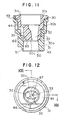
- Fig. 11 is a cross-sectional view taken along the line XI - XI of Fig. 10;
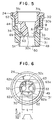
- Fig. 12 is a bottom view of an essential portion of a fourth embodiment of the present invention;
- Fig. 13 is a cross-sectional view taken along the line XIII - XIII of Fig. 12;
- Fig. 14 is a bottom view of an essential portion of a fifth embodiment of the present invention;
- Fig. 15 is a cross-sectional view taken along the line XV - XV of Fig. 14;
- Fig. 16 is a bottom view of an essential portion of a sixth embodiment of the present invention;
- Fig. 17 is a cross-sectional view taken along the line XVII - XVII of Fig. 16.
-
- The preferred embodiments of the present invention will be described below with reference to the accompanying drawings.
- The first embodiment of the present invention in which the invention is applied to a fuel supply system for gasoline internal combustion engines will be described with reference to Figs. 1 to 8.
- As shown in Figs. 2 and 3,
intake valves internal combustion engine 100 atintake ports intake valves intake ports wall 114 is formed between theintake ports intake pipe 62 has anintake passage 61 which communicates with theintake port 112. Anintake throttle valve 63 for opening and closing theintake passage 61 is turnably mounted in theintake pipe 62. A fuel injection valve 1 is mounted in an outer wall of theintake pipe 62 on the downstream side of theintake throttle valve 63 so as to spray fuel toward each of theintake valves air supply passage 65 is provided which communicates theintake passage 61 on the upstream side of theintake throttle valve 63 with an assist air passage of the fuel injection valve 1 to be described later. Anelectromagnetic valve 66 is provided in an intermediate portion of theair supply passage 65 to adjust the rate at which assist air is supplied to the fuel injection valve 1. - As shown in Fig. 4, the fuel injection valve 1 which is operated electromagnetically is mounted in a delivery pipe 2 shown in Fig. 2. The delivery pipe 2 supplies fuel to each of cylinders of the internal combustion engine. The fuel injection valve 1 has a housing 3 having in the form of a stepped cylinder. An
electromagnetic coil 5 is disposed in a large-diameter portion of the housing 3 to be wound around a spool 4. A cylindrical iron core 6 is provided to extend through the spool 4 from a position above the spool 4. An adjustingpipe 7 is provided in the iron core 6 slidably in an axial direction. - A
nozzle body 10 is fitted onto and fixed to a small-diameter portion of the housing 3 with aspacer 9 interposed therebetween. Afuel injection port 12 is formed in an end surface of a downwardly projecting portion of thenozzle body 10. Aneedle valve 14 is slidably inserted in thenozzle body 10 from the upper opening of the same. Apintle 16 is formed at a tip end of theneedle valve 14. Thepintle 16 extends through thefuel injection port 12 with a gap therebetween. Astopper 18 is formed substantially at a center of theneedle valve 14 so as to face thespacer 9. Amovable core 20 facing the iron core 6 is connected to an upper end portion of theneedle valve 14. Themovable core 20 is urged downward by acoil spring 22 disposed between the iron core 6 and the adjustingpipe 7. At the end portion of thenozzle body 10 in which thefuel injection port 12 is formed, a splittype resin sleeve 24 is provided to surround the end portion of thenozzle body 10. - As shown in Figs. 1 and 5, the
sleeve 24 is constituted by aninner sleeve nozzle 30 and anouter cover nozzle 31. Thesleeve nozzle 30 and thecover nozzle 31 which form thesleeve 24 are made of a material such as 6-6 nylon (containing 30 wt% glass), polyacetal, or PPS (polyphenylene sulfide). - The
inner sleeve nozzle 30 has two fuelflow separating holes flow separating holes inner sleeve nozzle 30 has a taperedsurface 30a and an annular steppedportion 30b in its outer wall surface. - The
outer cover nozzle 31 has holes, e.g., sixholes 44 and 45 (holes 45 not shown) for forming an air inlet to extend from its inner surface to its outer surface. The sectional area of each of theholes 44 and 45 suffices to be equal to or greater than the sectional area of a passage defined between achannel 34 or 35 (channel 35 not shown) and an inner surface of thecover nozzle 31. At an end portion of thecover nozzle 31 are formed adiffusion section 50 for guiding sprays of atomized fuel agitated by assist air, askirt portion 49 for limiting the divergence of fuel spray angles, and a chamferedportion 51 for positioning at the time of automatic assembly. Gaps A and B shown in Fig. 5 are formed to provide a clearance of about 0.1 to 0.3 mm, thereby preventing fusing and welding of portions of thesleeve nozzle 30 and thecover nozzle 31 other than the steppedportion 30b at the time of ultrasonic welding as well as clogging in the assist air passage caused by occurrence of an unnecessary burr. - As shown in Fig. 2, a passage inside the delivery pipe 2 through which fuel introduced through the fuel inlet flows is formed between a first O-
ring 58 and a second O-ring 59. Air introduced via anair passage 2a formed in the delivery pipe 2 is sealed in a diametral direction between the second O-ring 59 and a third O-ring 60. - As shown in Figs. 1 and 5, the fuel
flow separating hole 33 is formed to have a tapered cylindrical shape to be reduced in diameter toward its downstream end. A pair ofair holes lower end surface 30c of thesleeve nozzle 30 on the opposite sides of the opening ends of the fuelflow separating holes flow separating holes lower end surface 30c of thesleeve nozzle 30. Opposite slit ends 62a, 62b, 63a, and 63b of the straight air slits 62 and 63 are closed in the vicinity of the sleeve nozzle outer wall. Intermediate air passages 68 and 69 (passage 68 is not shown) for supply of air, leading to the opening ends of the air slits 62 and 63 extend obliquely from the air passages constituted bychannels 34. - Assist air flowing out of the air slits 62 and 63 has a flow rate distribution shown in Fig. 6. That is, the air flow rate is increased about a central portion of each of the air slits 62 and 63. Referring to Fig. 6, the length of the air slits 62 and 63 is selected to be longer than the distance between the centers of the two fuel
flow separating holes flow separating holes - Next, flowing of mixture of fuel jetted through the fuel
flow separating holes - As shown in Figs. 7 and 8, jets of fuel from the fuel
flow separating holes skirt portion 49, thereby forming a flat sectoral flow surface F. That is, by forming flat jets of assist air, fuel jets flowing from the fuelflow separating holes wall 114 shown in Fig. 3. Therefore, fuel sprays thereby supplied to the combustion chamber 11 has such good characteristics that fuel can be completely combusted with air. - Specifically, in this embodiment, a wall or curtain of an assist air flow is formed by assist air flows from the air slits 62 and 63 so that sprays of atomized fuel can be positively separated in two directions. Moreover, by the effect of an air flow rate distribution shown in Fig. 6, the assist air flow wall is particularly strong at a central portion, so that the flows in two directions can be separated more positively. Also, atomization of sprayed fuel can be suitably maintained or promoted by relatively weak assist air flows from end portions of the air holes 62 and 63.
- Referring to Fig. 7, if the assist air jet angle is excessively large, the fuel spray angle is so small that the penetrating force is insufficient. If the assist air jet angle is excessively small, fuel cannot be adequately separated in two directions and cannot be sufficiently atomized. Therefore, the angle of inclination of the
air passage 69 is selected in view of the suitable range of the assist air jet angle. - Next, the procedure of manufacturing the
sleeve 24 in accordance with the first embodiment will be described. - The
cover nozzle 31 and thesleeve nozzle 30 are formed by injection molding. Thecover nozzle 31 and thesleeve nozzle 30 are joined integrally with each other by inserting thesleeve nozzle 30 into thecover nozzle 31 and fusing these nozzles. Thesleeve nozzle 30 is inserted through anopening 31c of thecover nozzle 31. - At the time of fusing, the
sleeve nozzle 30 is inserted into thecover nozzle 31, and the steppedportion 30b and a steppedportion 31b are pressed against each other by pressing thecover nozzle 31 and thesleeve nozzle 30. In this state, the steppedportion 30b is melted by ultrasonic wave vibration. A burr caused by ultrasonic waves enters aburr receiving space 53, so that any adverse influence upon the O-ring 60 shown in Fig. 2 can be avoided. While the steppedportion 30b is being melted by ultrasonic waves, thesleeve nozzle 30 is press-fitted into thecover nozzle 31. The application of ultrasonic waves is stopped when thetapered surface 30a is brought into abutment against thecover nozzle 31. - In this welding process, during press-fitting of the
sleeve nozzle 30 while melting the steppedportion 30b, the gaps A and B shown in Fig. 5 are maintained by aguide portion 52, thereby preventing generation of a burr due to unnecessary melting and welding. - Referring to Fig. 4, the
sleeve nozzle 30 and the fuel injection valve 1 are assembled in such a manner that thesleeve nozzle 30 is press-fitted onto the outer circumference of thenozzle body 10 of the fuel injection valve 1 while agroove 10a and a projectingportion 30c are snap-fitted to prevent coming-off. Also at this time, thenozzle body 10 and thesleeve nozzle 30 are positioned in the direction of their relative rotation. - In the above-described embodiment, fuel introduced through the fuel inlet passes through a metering section and is jetted through the fuel injection holes 12, and the fuel jet is separated in two directions by the fuel
flow separating holes sleeve nozzle 30 and is immediately separated and atomized by air jets jetted through thepassage 69 and air slits 62 and 63 to be directed to the two intake valves while being maintained in specified directions. - The above-described embodiment has fuel flow separating holes for separating a fuel flow in two directions since there are provided two intake valves. However, a fuel supply system can be designed easily to distribute fuel in three or more directions as desired.
- A second embodiment of the present invention will be described with reference to Fig. 9.
- In the second embodiment, four sub air holes 74, 75, 76, and 77 are formed while main air holes 72 and 73 in the form of straight slits are formed to be smaller in length in lengthwise directions. The sub air holes 74 to 77 are formed as grooves in outer wall portions of the
sleeve nozzle 30. - According to the second embodiment, the main air holes 72 and 73 serve mainly to improve the function of separating a fuel spray in two directions, and the sub air holes 74 to 77 serve mainly to promote atomization of fuel.
- Next, a third embodiment of the present invention will be described with reference to Figs. 10 and 11.
- In the third embodiment, main air holes 82 and 83 in the form of curved slits are provided in place of the main air holes 62 and 63 of straight slits in the first embodiment shown in Fig. 1. The main air holes 82 and 83 are opened in the lower end surface of the
sleeve nozzle 30 in positions close to the fuelflow separating holes - Next, a fourth embodiment of the present invention will be described with reference to Figs. 12 and 13.
- In the fourth embodiment, main air holes 86 and 87 in the form of slits curved oppositely are provided in place of the curved main air slits 82 and 83 shown in Fig. 10. The main air holes 86 and 87 are opened in the
lower end surface 30c of thesleeve nozzle 30 in positions close to the fuelflow separating holes - A fifth embodiment of the present invention will be described with reference to Figs. 14 and 15.
- In the fifth embodiment, main air holes 90 and 91 and sub air holes 92 and 93 are formed in place of the straight air slits 62 and 63 shown in Fig. 1. The main air holes 90 and 91 are formed to be smaller in length in lengthwise directions, and the sub air holes 92 and 93 are formed as grooves in outer wall portions of the
sleeve nozzle 30. - A sixth embodiment of the present invention will be described with reference to Figs. 16 and 17.
- In the sixth embodiment, four sub air holes 94, 95, 96, and 97 are formed in place of the curved sub air slits 92 and 93 shown in Fig. 14 to be recessed in the
cover nozzle 31. - In the above-described embodiments, a fuel jet jetted from the single
fuel injection hole 12 is distributed into fuel jets flowing in two directions through the fuelflow separating holes - The above-described embodiments may be modified in such a manner that a plurality of fuel injection holes are provided to form fuel sprays flowing in two or more directions. In the case of such an arrangement, a thin orifice plate is mounted in place of the
fuel injection port 12, and a plurality of fuel injection ports are formed in this orifice plate. For example, four fuel injection ports having a fuel metering function are formed and two of these injection ports are directed together toward one of the intake valves while the other two injection ports are directed toward the other intake valve. In this case, the injector main body including the orifice plate serves as a fuel spray forming member. Further, substantially large holes are formed in place of the fuelflow separating holes - Positions at which assist air jet flows impinge against the fuel jets must be selected according to the spray configuration. If the fuel jet outlets and the assist air jet outlets are close to each other, the direction of the assist air jets may be parallel to the fuel jets.
- Further, two-dimensionally-flowing assist air jets may be applied to a single fuel jet flow, whereby spreading of a single fuel spray can be suppressed while the atomization of fuel is promoted.
- In the above-described embodiments of the present invention, air holes in the form of slits extending straight or curvedly are formed on the opposite sides of injection hole openings, and assist air flows are jetted two-dimensionally from these air slits to impinge against fuel jets. This arrangement ensures that fuel jetted through the flow separating holes can be suitably atomized while being maintained in a state of being separated from each other and being caused to flow independently in two directions.
- Thus, in the arrangement of the embodiments, flat flow surfaces can be formed because air slits are provided on the opposite sides of the two flow separating holes, and, by these flat flow surfaces, two fuel jets from the two flow separating holes can be suitably atomized and caused to flow constantly in the desired jetting directions without being mixed with each other. Moreover, spreading of the atomized fuel sprays in a vertical direction can be suppressed by the flat flow surfaces.
- Specifically, due to the effect of jetting two-dimensionally-spreading assist air flows through the air slits, spreading of atomized fuel sprays is suppressed in a direction (illustrated as a vertical direction) perpendicular to the direction of arrangement of the two flow separating holes (illustrated as a horizontal direction), so that an amount of fuel attached to the intake passage wall is reduced. Also, the air slits are formed to be sufficiently long, whereby spreading of the atomized fuel sprays is suppressed in the direction of arrangement of the two flow separating holes (illustrated as a horizontal direction) without providing any sub air hole.
- The present invention makes it possible to obtain good characteristics of forming sprays of fuel jetted through a plurality of injection ports of a fuel injection valve with respect to separation of sprays in different directions, atomization, jetting angles and penetrating force.
- Fuel jetted through the injection ports of the fuel injection valve is jetted in separate jets from a plurality of fuel flow separating holes (32, 33) of a sleeve nozzle (30). On the other hand, band-like assist air flows are jetted in a two-dimensional manner from slit-like air holes (62, 63) opened on the opposite sides of the fuel flow separating holes (32, 33) to impinge obliquely against the jetted fuel. Atomization of fuel jetted through the plurality of fuel flow separating holes (32, 33) is thereby promoted and fuel sprays are accurately separated and supplied independently in two directions toward two intake valves while the directions of jets from the injection ports of the fuel injection valve are maintained, thus injecting and supplying fuel. As a result, an amount of fuel impinging directly against walls which separates and forms two intake ports is reduced and an amount of atomized sprayed fuel directly entering a combustion chamber from the intake ports is therefore increased, thereby improving combustion characteristics.
Claims (10)
- A fuel supply system for internal combustion engines which supplies a fuel spray combustible in a combustion chamber of said internal combustion engine, said fuel supply system comprising
fuel jet forming means constituted by a sleeve nozzle (30, 31), wherein flow separating holes for forming fuel jets flowing in predetermined directions and a plurality of slit-like air holes (62, 63; 72, 73; 82, 83; 86, 87, 90, 91, 92, 93) for jetting assist air along the sides of said fuel jets are formed in said sleeve nozzle (30, 31),
characterized in that
said slit-like air holes are arranged in said sleeve nozzle (30, 31) on opposite sides and in the vicinity of said fuel jets and extend in a direction in which said flow separating holes are aligned, wherein opposite slit ends (62a, 62b, 63a, 63b) of said air slits are closed in the vicinity of the outer wall of said sleeve nozzle (30, 31) so that assist air is jetted in a band-like manner such that said assist air jets sandwich the fuel jets therebetween. - A fuel supply system according to claim 1,
characterized in that
said fuel flow separating holes separate fuel at least into a first fuel jet flowing in a first direction and a second fuel jet flowing in a second direction. - A fuel supply system according to claim 2,
characterized in that
said fuel jet forming means has a first flow separating hole (32) through which said first fuel jet is jetted and a second flow separating hole (33) through which said second fuel jet is jetted, said first and second flow separating holes being formed to have openings arranged on the same plane. - A fuel supply system according to claim 2,
characterized in that
said slit-like air holes are formed close to said first and second flow separating holes. - A fuel supply system according to one of claims 1 to 4,
characterized in that
said slit-like air holes are inwardly inclined so that assist air jets impinge against the fuel jets from said both sides of the fuel jets. - A fuel supply system according to one of claims 1 to 5,
characterized by
a sleeve (24) mounted on an end of a nozzle body (10) of a fuel jet valve (1), said sleeve (24) comprises said sleeve nozzle (30) and an outer cover nozzle (31) surrounding said sleeve nozzle (30). - A fuel supply system according to claim 6,
characterized in that
additional assist air passages (74-77; 92-97) are formed between said sleeve nozzle (30) and said cover nozzle (31). - A fuel supply system according to claim 2,
characterized in that
said first fuel jet is directed to a first intake valve of the internal combustion engine while said second fuel jet is directed to a second intake valve of the internal combustion engine. - A fuel supply system according to claim 3,
characterized in that
said slit-like air holes extend substantially over at least an area between said first and second fuel flow separating holes (32, 33). - A fuel supply system according to claim 9,
characterized in that
said slit-like air holes are larger in length than at least a distance between centers of said first and second fuel flow separating holes (32, 33).
Applications Claiming Priority (3)
| Application Number | Priority Date | Filing Date | Title |
|---|---|---|---|
| JP24189/93 | 1993-02-12 | ||
| JP5024189A JPH06241147A (en) | 1993-02-12 | 1993-02-12 | Fuel feeding device for internal combustion engine |
| JP2418993 | 1993-02-12 |
Publications (2)
| Publication Number | Publication Date |
|---|---|
| EP0610932A1 EP0610932A1 (en) | 1994-08-17 |
| EP0610932B1 true EP0610932B1 (en) | 1999-07-14 |
Family
ID=12131385
Family Applications (1)
| Application Number | Title | Priority Date | Filing Date |
|---|---|---|---|
| EP94102064A Expired - Lifetime EP0610932B1 (en) | 1993-02-12 | 1994-02-10 | Fuel supply system for internal combustion engine |
Country Status (6)
| Country | Link |
|---|---|
| US (1) | US5666920A (en) |
| EP (1) | EP0610932B1 (en) |
| JP (1) | JPH06241147A (en) |
| KR (1) | KR100294369B1 (en) |
| CA (1) | CA2115535C (en) |
| DE (1) | DE69419440T2 (en) |
Families Citing this family (5)
| Publication number | Priority date | Publication date | Assignee | Title |
|---|---|---|---|---|
| JPH0821342A (en) * | 1994-07-07 | 1996-01-23 | Yamaha Motor Co Ltd | Fuel injection type engine |
| DE19519838C2 (en) * | 1995-05-31 | 1997-11-20 | Bosch Gmbh Robert | Method for influencing the alignment of fuel on a fuel injector and fuel injector |
| US6032652A (en) * | 1997-11-27 | 2000-03-07 | Denso Corporation | Fuel injection system having variable fuel atomization control |
| EP1874480A2 (en) * | 2005-02-04 | 2008-01-09 | Murad M. Ismailov | Fuel injection system and fuel injector with improved spray generation |
| WO2008157823A1 (en) * | 2007-06-21 | 2008-12-24 | Deyang Hou | Premix combustion methods, devices and engines using the same |
Family Cites Families (18)
| Publication number | Priority date | Publication date | Assignee | Title |
|---|---|---|---|---|
| DE419206C (en) * | 1924-04-25 | 1925-09-29 | Alfred Prinz | Gas burner |
| FR2397885A2 (en) * | 1977-03-10 | 1979-02-16 | Skm Sa | HYDROSTATIC SPRAY PAINT SPRAY GUN |
| JPS6056908B2 (en) * | 1978-11-06 | 1985-12-12 | 株式会社日立製作所 | Fuel control device for fuel injection system |
| JPS6014274B2 (en) * | 1981-03-31 | 1985-04-12 | 松下電工株式会社 | Solar thermal water heating device |
| JPS59131575U (en) * | 1983-02-23 | 1984-09-04 | トヨタ自動車株式会社 | Fuel injection valve for electronically controlled engines |
| JPS603278A (en) * | 1983-06-20 | 1985-01-09 | Sony Corp | Solid-state image pickup device |
| JPS63160376A (en) * | 1986-12-24 | 1988-07-04 | Toshiba Corp | Semiconductor device |
| JPS63314363A (en) * | 1987-06-17 | 1988-12-22 | Nippon Carbureter Co Ltd | Fuel injection device |
| JPS6424161A (en) * | 1987-07-16 | 1989-01-26 | Nippon Denso Co | Solenoid operated fuel injection valve |
| US4982716A (en) * | 1988-02-19 | 1991-01-08 | Toyota Jidosha Kabushiki Kaisha | Fuel injection valve with an air assist adapter for an internal combustion engine |
| JP2562074B2 (en) * | 1990-06-15 | 1996-12-11 | 本田技研工業株式会社 | Fuel injection internal combustion engine |
| JPH0450472A (en) * | 1990-06-18 | 1992-02-19 | Nissan Motor Co Ltd | Fuel jet device for internal combustion engine |
| US5129381A (en) * | 1990-06-18 | 1992-07-14 | Nissan Motor Co., Ltd. | Fuel injection system for internal combustion engine |
| US5255658A (en) * | 1990-10-12 | 1993-10-26 | Coltec Industries Inc. | System and apparatus to improve atomization of injected fuel |
| US5220900A (en) * | 1991-02-07 | 1993-06-22 | Siemens Automotive L.P. | Air assist atomizer for fuel injector |
| DE4218896B4 (en) * | 1991-06-11 | 2006-01-19 | Denso Corp., Kariya | Fuel injection device for an internal combustion engine |
| JP2588803B2 (en) * | 1991-08-29 | 1997-03-12 | 本田技研工業株式会社 | Internal combustion engine |
| DE69106520T2 (en) * | 1991-10-29 | 1995-05-11 | Honda Motor Co Ltd | Injection internal combustion engine. |
-
1993
- 1993-02-12 JP JP5024189A patent/JPH06241147A/en active Pending
-
1994
- 1994-02-08 KR KR1019940002327A patent/KR100294369B1/en not_active IP Right Cessation
- 1994-02-09 US US08/193,852 patent/US5666920A/en not_active Expired - Fee Related
- 1994-02-10 EP EP94102064A patent/EP0610932B1/en not_active Expired - Lifetime
- 1994-02-10 DE DE69419440T patent/DE69419440T2/en not_active Expired - Fee Related
- 1994-02-11 CA CA002115535A patent/CA2115535C/en not_active Expired - Fee Related
Also Published As
| Publication number | Publication date |
|---|---|
| CA2115535A1 (en) | 1994-08-13 |
| DE69419440T2 (en) | 2000-04-13 |
| DE69419440D1 (en) | 1999-08-19 |
| CA2115535C (en) | 2000-10-24 |
| KR100294369B1 (en) | 2001-10-22 |
| JPH06241147A (en) | 1994-08-30 |
| US5666920A (en) | 1997-09-16 |
| EP0610932A1 (en) | 1994-08-17 |
| KR940019983A (en) | 1994-09-15 |
Similar Documents
| Publication | Publication Date | Title |
|---|---|---|
| US5211682A (en) | Fuel feed apparatus of internal combustion engine and manufacturing method therefor | |
| EP0201190B1 (en) | Orifice director plate for electromagnetic fuel injector | |
| JP2996525B2 (en) | Fuel injection valve | |
| EP1108885B1 (en) | Direct injection fuel injector and internal combustion engine mounting the same | |
| US4570598A (en) | Air assist fuel distributor type fuel injection system | |
| US4771948A (en) | Combination of a fuel injection valve and a nozzle | |
| KR20010015858A (en) | Flat needle for pressurized swirl fuel injector | |
| KR100299834B1 (en) | Fluid injection nozzles and fuel injection valves using them | |
| JPH07259701A (en) | Electromagnetic fuel injection valve | |
| EP0610932B1 (en) | Fuel supply system for internal combustion engine | |
| EP0909920B1 (en) | Pressure swirl injector with angled cone spray for fuel injection | |
| US5655715A (en) | Fuel injection valve | |
| WO1997007333A1 (en) | Air assist atomizer for a split stream fuel injection | |
| GB2327461A (en) | An air assisted fuel injector for an internal combustion engine | |
| JP3756251B2 (en) | Fuel injection valve | |
| JP2584248B2 (en) | Fuel supply device for internal combustion engine | |
| EP0718492B1 (en) | Fuel injector | |
| JP2771254B2 (en) | Electromagnetic fuel injection valve | |
| US6045054A (en) | Air shroud for air assist fuel injector | |
| JPH0231785B2 (en) | DENJISHIKINENRYOFUNSHABEN | |
| KR20230130301A (en) | Injector | |
| JP2648691B2 (en) | Fuel injection valve | |
| JPH0828410A (en) | Fuel supply device for internal combustion engine | |
| JPH0450472A (en) | Fuel jet device for internal combustion engine | |
| JPH07259703A (en) | Electromagnetic fuel injection valve |
Legal Events
| Date | Code | Title | Description |
|---|---|---|---|
| PUAI | Public reference made under article 153(3) epc to a published international application that has entered the european phase |
Free format text: ORIGINAL CODE: 0009012 |
|
| AK | Designated contracting states |
Kind code of ref document: A1 Designated state(s): DE FR GB IT |
|
| 17P | Request for examination filed |
Effective date: 19940721 |
|
| 17Q | First examination report despatched |
Effective date: 19951218 |
|
| RAP1 | Party data changed (applicant data changed or rights of an application transferred) |
Owner name: DENSO CORPORATION |
|
| GRAG | Despatch of communication of intention to grant |
Free format text: ORIGINAL CODE: EPIDOS AGRA |
|
| GRAG | Despatch of communication of intention to grant |
Free format text: ORIGINAL CODE: EPIDOS AGRA |
|
| GRAG | Despatch of communication of intention to grant |
Free format text: ORIGINAL CODE: EPIDOS AGRA |
|
| GRAH | Despatch of communication of intention to grant a patent |
Free format text: ORIGINAL CODE: EPIDOS IGRA |
|
| GRAH | Despatch of communication of intention to grant a patent |
Free format text: ORIGINAL CODE: EPIDOS IGRA |
|
| GRAA | (expected) grant |
Free format text: ORIGINAL CODE: 0009210 |
|
| AK | Designated contracting states |
Kind code of ref document: B1 Designated state(s): DE FR GB IT |
|
| REF | Corresponds to: |
Ref document number: 69419440 Country of ref document: DE Date of ref document: 19990819 |
|
| ITF | It: translation for a ep patent filed |
Owner name: SOCIETA' ITALIANA BREVETTI S.P.A. |
|
| ET | Fr: translation filed | ||
| REG | Reference to a national code |
Ref country code: GB Ref legal event code: 746 Effective date: 20000201 |
|
| PLBE | No opposition filed within time limit |
Free format text: ORIGINAL CODE: 0009261 |
|
| STAA | Information on the status of an ep patent application or granted ep patent |
Free format text: STATUS: NO OPPOSITION FILED WITHIN TIME LIMIT |
|
| 26N | No opposition filed | ||
| PGFP | Annual fee paid to national office [announced via postgrant information from national office to epo] |
Ref country code: DE Payment date: 20010205 Year of fee payment: 8 |
|
| PGFP | Annual fee paid to national office [announced via postgrant information from national office to epo] |
Ref country code: GB Payment date: 20010207 Year of fee payment: 8 |
|
| PGFP | Annual fee paid to national office [announced via postgrant information from national office to epo] |
Ref country code: FR Payment date: 20010213 Year of fee payment: 8 |
|
| REG | Reference to a national code |
Ref country code: GB Ref legal event code: IF02 |
|
| PG25 | Lapsed in a contracting state [announced via postgrant information from national office to epo] |
Ref country code: GB Free format text: LAPSE BECAUSE OF NON-PAYMENT OF DUE FEES Effective date: 20020210 |
|
| PG25 | Lapsed in a contracting state [announced via postgrant information from national office to epo] |
Ref country code: DE Free format text: LAPSE BECAUSE OF NON-PAYMENT OF DUE FEES Effective date: 20020903 |
|
| GBPC | Gb: european patent ceased through non-payment of renewal fee |
Effective date: 20020210 |
|
| PG25 | Lapsed in a contracting state [announced via postgrant information from national office to epo] |
Ref country code: FR Free format text: LAPSE BECAUSE OF NON-PAYMENT OF DUE FEES Effective date: 20021031 |
|
| REG | Reference to a national code |
Ref country code: FR Ref legal event code: ST |
|
| PG25 | Lapsed in a contracting state [announced via postgrant information from national office to epo] |
Ref country code: IT Free format text: LAPSE BECAUSE OF NON-PAYMENT OF DUE FEES Effective date: 20050210 |