EP0403753A2 - Generator von ungenauen Regeln - Google Patents
Generator von ungenauen Regeln Download PDFInfo
- Publication number
- EP0403753A2 EP0403753A2 EP90107256A EP90107256A EP0403753A2 EP 0403753 A2 EP0403753 A2 EP 0403753A2 EP 90107256 A EP90107256 A EP 90107256A EP 90107256 A EP90107256 A EP 90107256A EP 0403753 A2 EP0403753 A2 EP 0403753A2
- Authority
- EP
- European Patent Office
- Prior art keywords
- rules
- fuzzy
- sets
- rule
- rule generator
- Prior art date
- Legal status (The legal status is an assumption and is not a legal conclusion. Google has not performed a legal analysis and makes no representation as to the accuracy of the status listed.)
- Withdrawn
Links
Images


Classifications
-
- G—PHYSICS
- G06—COMPUTING OR CALCULATING; COUNTING
- G06N—COMPUTING ARRANGEMENTS BASED ON SPECIFIC COMPUTATIONAL MODELS
- G06N7/00—Computing arrangements based on specific mathematical models
- G06N7/02—Computing arrangements based on specific mathematical models using fuzzy logic
- G06N7/026—Development tools for entering the parameters of a fuzzy system
-
- G—PHYSICS
- G05—CONTROLLING; REGULATING
- G05B—CONTROL OR REGULATING SYSTEMS IN GENERAL; FUNCTIONAL ELEMENTS OF SUCH SYSTEMS; MONITORING OR TESTING ARRANGEMENTS FOR SUCH SYSTEMS OR ELEMENTS
- G05B11/00—Automatic controllers
-
- G—PHYSICS
- G06—COMPUTING OR CALCULATING; COUNTING
- G06F—ELECTRIC DIGITAL DATA PROCESSING
- G06F8/00—Arrangements for software engineering
-
- G—PHYSICS
- G06—COMPUTING OR CALCULATING; COUNTING
- G06N—COMPUTING ARRANGEMENTS BASED ON SPECIFIC COMPUTATIONAL MODELS
- G06N5/00—Computing arrangements using knowledge-based models
- G06N5/04—Inference or reasoning models
- G06N5/048—Fuzzy inferencing
Definitions
- the present invention relates to a fuzzy rule generator for generating new fuzzy rules according to existing
- a predetermined set of rules are activated when an input signal is supplied to a fuzzy deduction unit, and the control action for the control object is determined by deduction according to the activated set of rules.
- the set of rules include a large number of fuzzy rules which are allocated for different control situations, and such fuzzy rules are typically expressed in the form of if-then statements.
- a primary object of the present invention is to provide a fuzzy rule generator which allows existing sets of rules to be effectively utilized if any such sets of rules indeed exist, and simplifies the work of creating and modifying fuzzy rules by generating or synthesizing new sets of rules by making use of existing sets of rules.
- a second object of the present invention is to provide a fuzzy rule generator which ensures generation of rational sets of fuzzy rules free from conflicting fuzzy rules.
- a third object of the present invention is to provide a fuzzy rule generator which allows fuzzy rules to be generated more or less automatically, and yet ensures a satisfactory control performance.
- a fourth object of the present invention is to provide a fuzzy rule generator which allows the system operator to obtain desired control characteristics and system stability.
- a fuzzy rule generator for generating fuzzy rules, comprising: selection means for selecting two or more sets of rules from a plurality of basic sets of rules; and computing means for generating a new set of rules by carrying out a synthetic arithmetic operation based on a predetermined set of rules for synthesis.
- the synthetic arithmetic operation may consist of either addition or subtraction.
- the basic sets of rules are stored in storage means forming a part of the fuzzy rule generator.
- a new set of rules are generated by making use of two or more selected basic sets of rules for each new application, the work of creating and modifying rules is simplified, and existing sets of rules are effectively utilized. Furthermore, by accumulating the newly generated sets of rules in the storage means, they also may be effectively utilized for synthesizing new sets of rules in future applications. Also, even when the sets of basic rules contain mutually conflicting rules, as they may be appropriately modified during the process of synthesis according to a prescribed rule, destruction of the basic characteristics of the sets of rules are avoided during the process of synthesis.
- the rule generating means may be provided with a function to modify one of the basic sets of rules according to a prescribed rule when the basic sets of rules include conflicting rules.
- a constraint on the synthesized set of fuzzy rules so as to ensure a stability of the control object. This can be accomplished strictly manually or, alternatively, at least partly automatically by making use of a Liapunov function defined for its control object, and modifying the synthesized set of rules so as to ensure stability to its control object.
- Figure 1 shows an overall structure of an embodiment of the fuzzy rule generator according to the present invention, and this rule generator comprises a rule selector 1, a synthesizer 2, and a rule set up unit 3.
- the rule selector 1 selects two or more sets of rules that are going to be used as a basis for a synthetic process from n number of sets of rules.
- the synthesizer 2 carries out a synthetic arithmetic operation on the sets of rules selected by the rule selector 1, and creates a new set of rules.
- the rule set up unit 3 sets up the new set of rules created by the synthesizer 2 on a fuzzy deduction unit (not shown in the drawings).
- the rule selector 1 selects two sets of rules, and the synthesizer 2 extracts those fuzzy rules which contain applicable conditions and creates a new set of rules by carrying out addition and/or subtraction according to predetermined addition or subtraction rules.
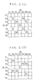
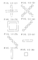
- Figures 2 (1) and (2) show two sets of rules selected by the rule selector 1 in the form of matrices.
- the first and second sets of rules each define what actions to be taken for inputs ⁇ 1 and ⁇ 2.
- an output u is to be ZR when one of the inputs ⁇ 1 is PM and the other input ⁇ 2 is PM.
- PM and ZR are fuzzy labels which consist of seven kinds: PL (positive large), PM (positive medium), PS (positive small), ZR (zero), NS (negative small), NM (negative medium), and NL (negative large).
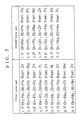
- Figure 3 shows the first set of rules on the left side and the second set of rules on the right side in a table each in the form of if-then statements.
- the first set of rules contain 9 fuzzy rules while the second set of rules contain 7 fuzzy rules.
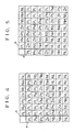
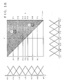
- the synthesizer 2 reads out data related to the fuzzy rules included in the sets of rules to carry out a synthetic arithmetic operation thereon either according to the addition rule shown in Figure 4 or according to the subtraction rule shown in Figure 5.
- addition and subtraction rules serve as the rules for carrying out a synthetic arithmetic operation consisting of addition or subtraction as the case may be, and Figures 4 and 5 summarize these rules in the form of matrices.
- each intersection of labels selected from the column of labels a on the left side and the row of labels b on the upper side of each of the tables gives the label of the output u which is to be a result of addition or subtraction.
- the intersection of each combination of vertical and lateral labels indicates a result of a synthetic arithmetic operation based on addition in the form of a label
- the intersection of each combination of vertical and lateral labels indicates a result of a synthetic arithmetic operation based on subtraction in the form of a label.
- the label of the result of the arithmetic operation is given by PL.
- Figure 6 summarizes a new set of rules which are thus generated by carrying out synthetic arithmetic operations based on addition, in the form of a matrix.
- the shaded areas represent the labels obtained by the synthetic arithmetic operations.
- the remaining labels correspond to those not having common conditions, and, in this case, the label of the output of each of such fuzzy rules is used as it is.
- the new set of rules generated or synthesized from the first and second sets of rules may be expressed in the form of if-then statements as given in the following:
- the set of rules thus generated are sent to the rule set up unit 3, and a certain set up operation is carried out at the fuzzy deduction unit.
- a rule generator for generating fuzzy rules comprising: selection means for selecting two or more sets of rules from a plurality of basic sets of rules; and computing means for generating a new set of rules by carrying out a synthetic arithmetic operation based on rules for synthesis, a new set of rules can be easily generated by carrying out a simple arithmetic operation for each application. Therefore, generation and modification of rules are simplified and speeded up, with additional benefits arising from an efficient utilization of existing sets of rules.
- Figure 8 shows a general structure of a second embodiment of the fuzzy rule generator according to the present invention, and this rule generator comprises a storage unit 11, a rule selector 12, a rule synthesizer 13, a rule modifier 14, and a rule set up unit 15.
- the storage unit 11 stores a plurality of basic sets of rules.
- the rule selector 12 selects two or more basic sets of rules serving as a basis for a subsequent process of synthesis from the storage unit 11, and supply them to the rule synthesizer 13.
- the rule synthesizer 13 synthesizes a desired set of rules by using the basic sets of rules selected by the rule selector 12 according to a prescribed rule.
- This rule synthesizer 13 has a function to modify one of the sets of rules according to a prescribed rule when the sets of basic rules serving as a basis for the process of synthesis contain mutually conflicting rules.
- the rule modifier 14 carries out modification of the set of rules generated by the rule generator 13 and add rules thereto as required.
- the rule set up unit 15 sets up the new set of rules generated by the rule synthesizer 13 and the rule modifier 14 on a fuzzy deduction unit (not shown in the drawings).
- Figure 9 shows the format of the sets of basic rules that are to be initially stored in the storage unit 11.
- two inputs ⁇ 1 and ⁇ 2 are indicated on the left side and the upper end, respectively, as fuzzy labels.
- the intersection of each combination of vertical and horizontal labels gives an output u defining what action should be taken in the form of a fuzzy label.
- there are seven fuzzy labels consisting of PL (positive large), PM (positive medium), PS (positive small), ZR (zero), NS (negative small), NM (negative medium), and NL (negative large).
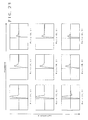
- Figures 10(1) through 10(8) show examples of the sets of basic rules which are stored in the storage unit 11 in advance.
- Each set of basic rules are characterized by the pattern of fuzzy labels of the output as listed in the matrix of Figure 2: the pattern of Figure 10(1) has the shape of vertical and horizontal lines crossing each other; the pattern of Figure 10(2) has the shape of a pair of oblique lines crossing each other; the pattern of Figure 10(3) has the shape of a rectangular ring; the pattern of Figure 10(4) has the shape of a leftwardly slanting line; the pattern of Figure 10(5) has the shape of a rightwardly slanting line; the pattern of Figure 10(6) has the shape of a horizontal line; the pattern of Figure 10(7) has the shape of a vertical line; and the pattern of Figure 10(8) has the shape of a rectangular block.
- the storage unit 11 stores an output pattern (shape) and the contents of fuzzy labels (components) for each set of the basic rules.
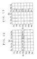
- Figure 11 shows an example of a set of rules having the pattern shown in Figure 10(6).
- the labels of the results correspond to the components of the basic rules, and, if the condition of the input ⁇ 1 is given by PS and it is expressed by M(PS), this set of basic rules may be expressed as M(PS,v1) where v1 represents the rule components).
- the rule selector 12 of the present embodiment selects two sets of basic rules and supply them to the rule synthesizer 13 which synthesizes a desired set of rules from these two sets of basic rules according to a prescribed rule.
- Figures 12 and 13 summarize two sets of basic rules selected by the rule selector 12 in the form of matrices, in which the set of rules of Figure 12 is of the type illustrated in Figure 10(6), and the set of rules of Figure 13 is of the type illustrated in Figure 10(7).
- the rule synthesizer 13 synthesizes a set of rules from the set of basic rules M(ZR,v1) shown in Figure 12 and the set of basic rules M(NS,v1) shown in Figure 13 by means of a synthetic arithmetic operation given by M(ZR,v1) + M(NS,v1), the set of basic rules shown in Figure 12 are given with a higher priority in the intended processing.
- the relevant component of the set of fuzzy rules having a lower priority is modified, for instance, from ZR to NS, after fixing the corresponding component (for instance NS) of the set of fuzzy ruled having a higher priority, and the amount of modification (NS - ZR) is computed by a subtraction unit.
- the process of synthesizing a new set of rules from two existing sets of rules may be carried out according to a predetermined set of rules such as the addition rules and the subtraction rules given in Figures 4 and 5 in a manner similar to that of the previous embodiment.
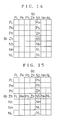
- Figure 16 shows the results of modifying the set of basic rules having a lower priority, and the set of rules shown in Figure 17 are ultimately generated by superimposing the modified set of basic rules over the set of basic rules given in Figure 12.
- the rule modifier 14 After modification and addition of rules are carried out by the rule modifier 14 on this set of rules as required, the obtained set of rules are sent to the rule set up unit 15 and are set up on the fuzzy deduction unit.
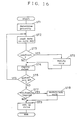
- Figure 16 shows the process of generating a new set of rules by this rule generator.
- step 1 a plurality of sets of basic rules which are to be selected from the storage unit 11 by the rule selector 12 for the purpose of synthesis are selected, and the priority of the sets of basic rules serving as a basis for synthesis are determined.
- step 2 after reading the patterns and the components of the rules for the two sets of basic rules serving as a basis for synthesis, the rule synthesizer 13 determines if there are any mutually conflicting rules. If there are no conflicting rules, the program flow advances to step 4 where the fuzzy rules of the sets of basic rules are deployed, and are converted into the forms of the fuzzy language equivalent to if-then statements.
- step 4 the fuzzy rules of the set of basic rules having a higher priority are deployed, and are converted into the forms of the fuzzy language equivalent to if-then statements, followed by deployment of the set of modified basic rules having a lower priority.
- step 6 it is determined if there still are any additional sets of basic rules which are to serve as a basis for the process of synthesis. If the result of this determination process is "yes”, the program flow returns to step 2, and the above mentioned process is repeated. If the determination result of step 6 is "no”, it is then determined whether any modification of the set of rules synthesized in step 7 is required or not. If the result of this determination process is "no", the rules are set up on the fuzzy deduction unit by the rule set up unit 15. However, if the result of the determination process in step 7 is "yes”, after the modification and addition of rules are carried out by the rule modifier 14 in step 8, the set of modified rules are set up on the fuzzy deduction unit.
- a plurality of sets of basic rules are stored in storage means in advance, a plurality of basic rules are selected from the storage means, and a desired set of rules are generated from the selected sets of rules according to a prescribed rule, generation and setting up of rules and modification of rules for each new application are extremely simplified, and speeded up, thereby allowing a significant reduction of burden on the system operator.
- the evaluation parameter which is to be set up on evaluation parameter set up means 22 may consist of a parameter a which determines a relation between a deviation e and a time differential value of the deviation e′ in a non-negative function of the deviation e and the time differential value of the deviation e′ which takes a minimum value when the deviation e and the differential value of the deviation e′ are both zero, and monotonically increases with increase in the deviation e.
- This function is a Liapunov function which gives a sufficient condition for the stability of the system. More detailed discussions on the properties of the Liapunov function and the method for evaluating the stability of a system by appropriately selecting the Liapunov function and evaluating it may be found in pages 291-341 of "Nonlinear Automatic Control" by John E. Gibson, McGraw-Hill, 1963, which is hereby incorporated into the disclosure by reference.
- control object By carrying out a control action in this fashion, the control object demonstrates a behavior highly responsive to the deviation but oscillatory as the value of ⁇ is increased, and a more controlled behavior when the value of ⁇ is made smaller.
- a preferred value of ⁇ is in the order of M/D or slightly larger than that.
- the adjustment of the value ⁇ is the ultimate item of adjustment in determining the behavior of the control object.
- a constraint parameter for constraining the behavior of the control object is received in addition to the control object parameters and the evaluation parameter.
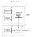
- a and B in Figure 17 correspond to these two parts of the third embodiment of the present invention.
- a constraint parameter is inputted to a fuzzy rule modifier 25 from constraint parameter set up means 24.
- Figure 19 shows such an example of constraint imposed upon the fuzzy rules.
- the diagram of Figure 21 shows a rule table in the form of a matrix which determines how the fuzzy rules should be modified according to the selection of the degree of constraint (which in this case consists of three levels, small (S), medium (M) and big (B).
- This table is stored in the constraint parameter set up means 24 which acts upon the fuzzy rule modifier 25 as shown in Figure 17.
- Figures 22 and 23 show the patterns and the contents of the fuzzy rule matrices for different levels of the evaluation parameter ⁇ and the constraint parameter, and step responses obtained by the associated sets of fuzzy rules.
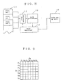
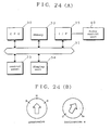
- FIG 24(A) shows an embodiment of the hardware structure of the fuzzy rule generator according to the present invention.
- This fuzzy rule generator comprises a small computer controlled by a CPU 30, and is connected to memory 32 and a keyboard 33 via a bus 31, and a display unit 34 via an interface 35.
- the memory 32 stores programs and arithmetic formulae for computing fuzzy rules
- an operation board 33 is provided with a keyboard and parameter set up dials (see Figure 24(B)) for allowing the system operator to set up data on the parameters.
- the display unit 34 displays selected parameters and computed fuzzy rules.
- the interface 35 is connected to a fuzzy control unit 40.
- Figure 25 shows a block diagram of the fuzzy control unit 40 which comprises a fuzzy deduction unit 41, an output amplifier 46, and adders 47 and 48 for computing deviations e and e′.
- the adders 47 and 48 receive target values ⁇ r and ⁇ r′ and actual values ⁇ and ⁇ ′ obtained from the control object.
- the computed deviations e and e′ are supplied to the fuzzy deduction unit 41.
- the fuzzy deduction unit 41 comprises input units 42 and 43, a main deduction unit 44, and an output unit 45.
- the deviations e and e′ are supplied to the input units 42 and 43, respectively, and, after being scaled appropriately, are evaluated of their degrees of belongingness to membership functions of the conditions as well known to the art of fuzzy control.
- the degrees of belongingness are supplied to the deduction unit 44, and output values are obtained from corresponding fuzzy rules. These output values are supplied to the output unit 45, and the results obtained therefrom are supplied to the output amplifier 46.
- the output amplifier 46 supplies a drive current to a motor 49 by a magnitude in proportion to the associated result value to move the control object accordingly.
- the control object is provided with a position sensor and a speed sensor (not shown in the drawings), and the actual values ⁇ and ⁇ ′ detected thereby are used as negative inputs in the process of addition at the adders 47 and 48.
- Figure 26 is a flow chart showing the operation of the fuzzy rule generator.
- Inputs of control object parameters and an evaluation parameter ( ⁇ ) are received at ST1 and ST2.
- a stable region of fuzzy rules are computed according to the received parameters (ST3).
- it is determined whether a constraint parameter has been entered or not (ST4), and, if a constraint parameter has indeed been entered, fuzzy rules conforming with the constraint parameter are determined (ST5).
- These fuzzy rules are supplied to the main fuzzy control unit (ST6) before the operation of the control unit is concluded.
- those fuzzy rules which give rise to minimum output values within a stable region of the fuzzy rules are computed, and they are set as determined rules (ST7) which are to be supplied to the fuzzy control unit (ST6) before concluding this control action.
- step of ST3 corresponds to the action carried out by the basic fuzzy rule generating means A of the diagram given in Figure 17, and the step of ST5 corresponds to the action carried out by the modified fuzzy rule generating means B given in Figure 17.
- fuzzy rule generator of the present invention it is possible to generate fuzzy rules which can control the control object in a stable fashion simply by inputting approximate values of parameters and an evaluation parameter of the control object.
- a constraint parameter it is possible to generate fuzzy rules which can control the control object in a stable fashion.
- the evaluation parameter and the constraint parameter it is possible to control the behavior of the control object as desired.
Landscapes
- Engineering & Computer Science (AREA)
- Software Systems (AREA)
- Theoretical Computer Science (AREA)
- Physics & Mathematics (AREA)
- General Physics & Mathematics (AREA)
- General Engineering & Computer Science (AREA)
- Automation & Control Theory (AREA)
- Fuzzy Systems (AREA)
- Computing Systems (AREA)
- Mathematical Physics (AREA)
- Data Mining & Analysis (AREA)
- Evolutionary Computation (AREA)
- Artificial Intelligence (AREA)
- General Health & Medical Sciences (AREA)
- Health & Medical Sciences (AREA)
- Life Sciences & Earth Sciences (AREA)
- Biomedical Technology (AREA)
- Computational Linguistics (AREA)
- Molecular Biology (AREA)
- Algebra (AREA)
- Computational Mathematics (AREA)
- Mathematical Analysis (AREA)
- Mathematical Optimization (AREA)
- Pure & Applied Mathematics (AREA)
- Feedback Control In General (AREA)
- Devices For Executing Special Programs (AREA)
- Stored Programmes (AREA)
Applications Claiming Priority (6)
| Application Number | Priority Date | Filing Date | Title |
|---|---|---|---|
| JP1095880A JP2628912B2 (ja) | 1989-04-14 | 1989-04-14 | ルール生成装置 |
| JP95880/89 | 1989-04-14 | ||
| JP98358/89 | 1989-04-18 | ||
| JP1098358A JPH02277137A (ja) | 1989-04-18 | 1989-04-18 | ルール生成装置 |
| JP288219/89 | 1989-11-06 | ||
| JP1288219A JPH03148702A (ja) | 1989-11-06 | 1989-11-06 | ファジィルール生成装置 |
Publications (2)
| Publication Number | Publication Date |
|---|---|
| EP0403753A2 true EP0403753A2 (de) | 1990-12-27 |
| EP0403753A3 EP0403753A3 (de) | 1993-01-20 |
Family
ID=27307931
Family Applications (1)
| Application Number | Title | Priority Date | Filing Date |
|---|---|---|---|
| EP19900107256 Withdrawn EP0403753A3 (de) | 1989-04-14 | 1990-04-17 | Generator von ungenauen Regeln |
Country Status (2)
| Country | Link |
|---|---|
| EP (1) | EP0403753A3 (de) |
| KR (1) | KR940006917B1 (de) |
Cited By (1)
| Publication number | Priority date | Publication date | Assignee | Title |
|---|---|---|---|---|
| EP0600473A1 (de) * | 1992-12-02 | 1994-06-08 | Mitsubishi Denki Kabushiki Kaisha | Verfahren zur Synthetisierung einer Wissensbank und dieses gebrauchender Fuzzy-Kontroller |
-
1990
- 1990-04-13 KR KR1019900005105A patent/KR940006917B1/ko not_active Expired - Fee Related
- 1990-04-17 EP EP19900107256 patent/EP0403753A3/de not_active Withdrawn
Non-Patent Citations (4)
| Title |
|---|
| COMPUTATIONAL INTELLIGENCE vol. 4, no. 3, 1988, pages 244 - 264 D. DUBOIS ET AL 'Representation and combination of uncertainty with belief functions and possibility measures' * |
| IEEE EXPERT vol. 3, no. 1, 28 February 1988, NEW YORK US pages 33 - 41 , XP89 J.M. FRANCIONI ET AL 'A Software Engineering Tool for Expert System Design' * |
| JOURNAL A vol. 28, no. 3, July 1987, ANTWERPEN BE pages 126 - 130 D. HASPEL ET AL. 'The application of a real-time expert rule-based controller in the cement industry' * |
| PROC. 1988 IEEE INT. CONF. ON SYSTEMS, MAN AND CYBERNETICS 8 August 1988, IEEE, NEW YORK, US. pages 63 - 65 MACHIAS, A.V. ET AL. 'Fuzzy clustering applied to transient stability evalution' * |
Cited By (2)
| Publication number | Priority date | Publication date | Assignee | Title |
|---|---|---|---|---|
| EP0600473A1 (de) * | 1992-12-02 | 1994-06-08 | Mitsubishi Denki Kabushiki Kaisha | Verfahren zur Synthetisierung einer Wissensbank und dieses gebrauchender Fuzzy-Kontroller |
| US5694525A (en) * | 1992-12-02 | 1997-12-02 | Mitsubishi Denki Kabushiki Kaisha | Method for filing and synthesizing of knowledge base and fuzzy control system using the same |
Also Published As
| Publication number | Publication date |
|---|---|
| EP0403753A3 (de) | 1993-01-20 |
| KR940006917B1 (ko) | 1994-07-29 |
| KR900016839A (ko) | 1990-11-14 |
Similar Documents
| Publication | Publication Date | Title |
|---|---|---|
| US5179634A (en) | System for synthesizing new fuzzy rule sets from existing fuzzy rule sets | |
| US5874955A (en) | Interactive rule based system with selection feedback that parameterizes rules to constrain choices for multiple operations | |
| US4757461A (en) | Process for graphically representing a structure | |
| US5712964A (en) | Computer graphics data display device and method based on a high-speed generation of a changed image | |
| US4962472A (en) | Automatic programming method for outputting figure elements of parts as well as part profile descriptions in response to a part profile request | |
| US4891763A (en) | NC program editing and programming device | |
| EP0514101A2 (de) | Verfahren zur Bedienung eines Rechnersystems zur Lösung numerischer Planungsprobleme | |
| US5193144A (en) | Fuzzy system | |
| JP3076399B2 (ja) | ファジィ推論ルールの自動生成装置 | |
| EP0633515B1 (de) | Elektronisches Steuerungssystem | |
| US5982388A (en) | Image presentation device with user-inputted attribute changing procedures | |
| US5006977A (en) | Figure element revising method | |
| EP0403753A2 (de) | Generator von ungenauen Regeln | |
| JP2696972B2 (ja) | フアジイ・ルール発生装置および方法,ならびに確認装置および方法 | |
| EP0513689B1 (de) | Verfahren und Gerät zur Fertigstellung von Daten einer Mitgliedschaftsfunktion | |
| EP0382495B1 (de) | Figurverarbeitungsgerät | |
| US5305228A (en) | Tool axis direction calculation method | |
| US5805773A (en) | Fuzzy reasoning method and system | |
| JP2800309B2 (ja) | ハイブリッド制御装置及びハイブリッド制御方法 | |
| JP2643295B2 (ja) | ファジィ制御演算装置およびファジィ推論方法 | |
| US5072398A (en) | Figure definition method in automatic programming | |
| JPH06348307A (ja) | 言語学的制御の評価方法 | |
| US5151864A (en) | Method of generating cutting passes of complex curved surface | |
| JP2810051B2 (ja) | 自動要素分割装置 | |
| JP2713265B2 (ja) | 画像表示装置 |
Legal Events
| Date | Code | Title | Description |
|---|---|---|---|
| PUAI | Public reference made under article 153(3) epc to a published international application that has entered the european phase |
Free format text: ORIGINAL CODE: 0009012 |
|
| 17P | Request for examination filed |
Effective date: 19900511 |
|
| AK | Designated contracting states |
Kind code of ref document: A2 Designated state(s): AT BE CH DE DK ES FR GB GR IT LI NL SE |
|
| PUAL | Search report despatched |
Free format text: ORIGINAL CODE: 0009013 |
|
| AK | Designated contracting states |
Kind code of ref document: A3 Designated state(s): AT BE CH DE DK ES FR GB GR IT LI NL SE |
|
| 17Q | First examination report despatched |
Effective date: 19950802 |
|
| GRAG | Despatch of communication of intention to grant |
Free format text: ORIGINAL CODE: EPIDOS AGRA |
|
| GRAG | Despatch of communication of intention to grant |
Free format text: ORIGINAL CODE: EPIDOS AGRA |
|
| GRAH | Despatch of communication of intention to grant a patent |
Free format text: ORIGINAL CODE: EPIDOS IGRA |
|
| STAA | Information on the status of an ep patent application or granted ep patent |
Free format text: STATUS: THE APPLICATION IS DEEMED TO BE WITHDRAWN |
|
| 18D | Application deemed to be withdrawn |
Effective date: 19990227 |