EP0403218A2 - Bauteil für elektrische Schalter und damit gebildeter Schalter - Google Patents
Bauteil für elektrische Schalter und damit gebildeter Schalter Download PDFInfo
- Publication number
- EP0403218A2 EP0403218A2 EP90306374A EP90306374A EP0403218A2 EP 0403218 A2 EP0403218 A2 EP 0403218A2 EP 90306374 A EP90306374 A EP 90306374A EP 90306374 A EP90306374 A EP 90306374A EP 0403218 A2 EP0403218 A2 EP 0403218A2
- Authority
- EP
- European Patent Office
- Prior art keywords
- switch
- contact means
- contact
- coil spring
- switch blade
- Prior art date
- Legal status (The legal status is an assumption and is not a legal conclusion. Google has not performed a legal analysis and makes no representation as to the accuracy of the status listed.)
- Withdrawn
Links
Images
Classifications
-
- H—ELECTRICITY
- H01—ELECTRIC ELEMENTS
- H01H—ELECTRIC SWITCHES; RELAYS; SELECTORS; EMERGENCY PROTECTIVE DEVICES
- H01H11/00—Apparatus or processes specially adapted for the manufacture of electric switches
- H01H11/0056—Apparatus or processes specially adapted for the manufacture of electric switches comprising a successive blank-stamping, insert-moulding and severing operation
-
- H—ELECTRICITY
- H01—ELECTRIC ELEMENTS
- H01H—ELECTRIC SWITCHES; RELAYS; SELECTORS; EMERGENCY PROTECTIVE DEVICES
- H01H13/00—Switches having rectilinearly-movable operating part or parts adapted for pushing or pulling in one direction only, e.g. push-button switch
- H01H13/02—Details
- H01H13/26—Snap-action arrangements depending upon deformation of elastic members
- H01H13/28—Snap-action arrangements depending upon deformation of elastic members using compression or extension of coil springs
-
- F—MECHANICAL ENGINEERING; LIGHTING; HEATING; WEAPONS; BLASTING
- F02—COMBUSTION ENGINES; HOT-GAS OR COMBUSTION-PRODUCT ENGINE PLANTS
- F02B—INTERNAL-COMBUSTION PISTON ENGINES; COMBUSTION ENGINES IN GENERAL
- F02B1/00—Engines characterised by fuel-air mixture compression
- F02B1/02—Engines characterised by fuel-air mixture compression with positive ignition
- F02B1/04—Engines characterised by fuel-air mixture compression with positive ignition with fuel-air mixture admission into cylinder
Definitions
- This invention is concerned with the electrical switch art and more particularly with components in snap action mechanisms, the forming thereof and the mechanisms formed thereby.
- this invention relates to a precision compact elegant combination switch blade and contact means which is exceedingly useful in snap switch mechanisms -- particularly very tiny switch mechanisms which are denominated as being subminiature or sub-subminiature and the switch formed using the combination switch blade and contact means.
- snap switch mechanisms particularly very tiny switch mechanisms which are denominated as being subminiature or sub-subminiature and the switch formed using the combination switch blade and contact means.
- subminiature and sub-subminiature are inexact and cover a wide and overlapping range of sizes.
- the term "subminiature” will be used hereafter to denominate those switches which are among the smallest mechanically actuatable switches.
- Subminiature switches have been made heretofore. However these prior art subminiature switches do not fall in the category of being "high performance" switches. They are deficient in not being able to meet one or more of the following characteristics -- relatively large current capacity (1 Amp. resistive at 28 vdc or 115 vac, 60 Hz); high precision (movement differentials, pretravel, overtravel, all measured in terms of thousandths of one inch); ruggedness (able to withstand major shock forces, temperature extremes, tens of thousands of actuations, etc.) and reliability even when exposed to momentary short circuits of 50 or more times rated current carrying capacity.
- relatively large current capacity (1 Amp. resistive at 28 vdc or 115 vac, 60 Hz)
- high precision moving differentials, pretravel, overtravel, all measured in terms of thousandths of one inch
- ruggedness able to withstand major shock forces, temperature extremes, tens of thousands of actuations, etc.
- the other type of prior art blade is used with a coil spring and is a generally rigid pivotal contact carrying member, the cooperation being such that an actuator engages the coil spring to cause the line of action of the spring to overcenter and thereby move the movable contact mounted on the rigid contact carrying member.
- the coil spring type of switch has an advantage of being able to apply substantially more force to the movable contact in both its at rest position and when it has been moved to its overcentered position. This contact force is important to give the characteristic of ability to withstand extreme conditions of shock and vibration. The contact force also is important in preventing contact degradation. However and importantly, mere downsizing of these larger than subminiature size switches does not provide an acceptable high performance product of'subminiature size.
- the 8805/94 switch requirements called for a tiny in physical size switch which, excluding the terminals and the movable operating button, have an outer envelope dimensions of 0.100 inches plus or minus 0.007 inches in width; 0.300 plus or minus 0.010 inches length; and a height of 0.250 inches plus or minus 0.025 inches when including the raised cover area surrounding the actuator button.
- the electrical specification requires the ability to switch at least 1 Ampere resistive (0.5 Amperes inductive) at 28 vdc and 115 vac, 60 Hz at sea level with an electrical endurance of 25,000 cycles. In addition there is a requirement of a mechanical endurance of 100,000 cycles with a contact resistance after 25,000 cycles not to exceed 25 milliohms. After 100,000 cycles the contact resistance must not exceed 40 milliohms.
- the specification requires that the switch withstand defined very short durations of short circuits of 100 Amps. at 6 vdc and remain operative as defined.
- High performance operating characteristics also obtain in that it is required that the switch must switch current with a maximum actuating force of 4 ounces, a releasing force of 7/10 of an ounce and that a movement differential be provided of 4/1000 of an inch or less, a pretravel of at least 15/1000 of an inch and there be a minimum of 3/1000 of an inch of overtravel (and more would be desirable).
- a further sizable problem is to pack all of the very high precision movable parts in such a tiny space, while meeting the precision operating characteristics and simultaneously providing sufficient heft to meet the mechanical objectives of the specification.
- the invention features a unitary combination switch blade and contact means for a tiny rugged relatively large current carrying high precision snap switch of length less than one third of an inch and width less than one eighth of an inch, said unitary combination switch blade and contact means having a material thickness turned on edge so that the height of such unitary switch blade and contact means is substantially greater than the material thickness.
- the switch discussed below packs the operating parts in assembled relation internally of an envelope having a cubic interior space of approximately 78/1000 of an inch by 110/1000 of an inch by 281/1000 of an inch (all dimensions being at extreme of maximum tolerances).
- the method of forming the switch utilizes the pull/stretch action of the shearing edge of the stamping tool to form important curvilinear surfaces on the combination switch blade and contact carrying member, i.e. at the V shaped pivotal ends and at the spring engaging web between two slots in the bail portion of the U-shaped combination switch blade and contact carrying member.
- curvilinear surfaces provide low friction surfaces for engagement respectively with the cover and the spring as shall be described.
- the same concepts are also used in forming the spring engaging attachment surfaces of the yoke.
- the switch to be described is able to meet the difficult electrical, mechanical and operating characteristics aforenoted by the utilization of a novel unitary combination switch blade and contact means with other novel components and to be described novel relationships.
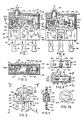
- FIGS. 1, 2 and 3 the components when assembled together form a subminiature unitary snap switch means 40.
- the drawings, Figs. 1, 2 and 3 are shown approximately ten times actual size.
- the snap switch means 40 comprises base means 42, cover means 44, fixed terminal means 46, yoke means 48, combination switch blade and contact means 50, coil spring means 52 and actuator means 54.
- the base means 42 and the fixed terminal means 46 are preferably molded as a unit.
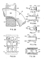
- the fixed terminal means 46 is made as a unit in continuous strip form as shown in Fig. 29,' and when removed from the molding machine are sheared off in a post molding operation to provide a configuration essentially as shown in Figs. 4, 5, 6 and 7 (they are connected together by scrap strip stock to be described respecting Fig. 29 prior to the shearing each from the other).
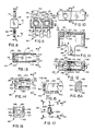
- the cover means 44 is shown in isolation in Figs. 10, 11, 12 and 13.
- the yoke means is shown in isolation and prior to assembly in Figs.
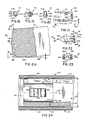
- the actuator (button) means 54 is shown in isolation in Figs. 17, 18, 19 and 20; and the preferred embodiment of the combination switch blade and contact means 50 is shown in isolation in Figs. 21, 21A, 22 and 23.
- the coil spring means is shown only in Figs. 1 - 3 and is not shown in isolation.
- the base means 42 is essentially rectilinear in configuration and has a pair of spaced through bores 56 for mounting purposes.
- the base means 42 has first, second and third fixed terminal/contact means 58, 60 and 62 integrally molded therewith.
- the first fixed terminal/contact means 58 is the upper normally closed switch contact
- the second fixed terminal/contact means 60 is the lower normally open contact of the assembly
- the third fixed terminal/contact means 62 is a part of the common contact/movable contact means of the assembly.
- connection means The exterior portions 64, 68 and 72 of the respectively fixed terminal/contact means 58, 60 and 62 are shown with a double turret type of connection means, it being appreciated that this type of connection means is to be considered illustrative only, there being many types and shape forms of exterior terminals as is well understood in the art.
- each of the fixed terminal/contact means 58, 60 and 62 also have respective interior portions 66, 70 and 74. They are preferably made by stamping from a single ribbon of sheet stock 57 in connected relationship to each other as shown in Fig. 29.
- the exterior ends of turret connection means 64, 68 and 72 for the fixed terminal/contact means are defined by shearing the connections to the sheet stock 57 at points 57a, 57b and 57c as shown.
- the sheet stock 57 is approximately .02 inches thick.
- the first, second and third terminal/contact means, 58, 60 and 62 as aforementioned, are tied together by scrap sheet stock connection strips 59 and 61 so that the three fixed terminals are in precise dimensional and spatial relationship each to the other and to the base means 42 during the molding process.
- the shearing action takes place to separate at the shear/connection points denominated 76a, 76b and 76c, it being appreciated that subsequent to molding, the strips 59 and 61 are cut away so as to leave the three fixed terminal/contact means in the shape and array as best shown in Fig. 9.
- the flat sheet stock 57 of which the terminal/fixed contacts 58, 60 and 62 are made may be, for example, raw coin grade silver (90% silver, 10% copper) and may or may not, depending on user needs, have gold flash or gold plate as called for in various military specifications.
- the connecting point 76a is purposefully located below the plane of surfaces 90a and 90b of the terminal/contact means 62 so as to not interfere with assembly of the yoke means 48 to surfaces 90a and 90b as shall become apparent.
- the interior portion 66 of the first fixed terminal/contact means 58 is formed with a vertical portion 78 and a horizontal portion 80.
- the horizontal portion 80 is the upper fixed normally closed contact of the switch. It will be seen that the vertical extent of the horizontal portion 80 as viewed in Fig. 1 is slightly greater than the material thickness and is relatively sturdy.
- the underside of the vertical portion 80 is the upper contact surface of the snap switch means 40.
- the relatively large mass of silver/copper metal and the composition of the portions 78 and 80 afford relative fast conduction of heat from the portion 80 to the exterior portion 64 and to the wires (not shown) to which the exterior portion will be connected.
- Heat is always associated with non super conducting electrical switch components, both at interruption of the electrical current and due to the resistive aspects (Joules losses) of passage of current. Interruption of the current provides arcing. In tiny switches, getting the heat quickly away from the contact area and into the exterior terminals and the heat sink provided by the exterior wires (not shown) is important to long mechanical and electrical switch life.
- the interior portion 70 of the second fixed terminal/contact means 60 has two portions raised above the horizontal top surface 82 of the base means 42, the lower contact portion 84 and the aforementioned cut off portion 76b. It will be noted that the width of portion 84 as viewed in Fig. 1 is approximately twice the thickness as shown in Fig. 7 to provide contact material mass.
- the upper fixed contact 80 lower surface is spaced from the upper surface of lower fixed contact 84 a dimension on the order of .063 inches which defines the vertical area in which the movable contact means 50 physically occupies the space, however there must also be sufficient margin left over so that the movable contact may move from its "made" position to interrupt and break the current flow during maximum rated electrical stress.
- the unitary combination switch blade and contact means 50 must for dielectric purposes, be spaced from a fixed contact. This spacing is necessary to prevent arcing under extreme vibration, shock, temperature extremes and altitude extremes of the Mil Spec MIL S 9804/94 (AR).
- the .063 inch area between the contacts is very tiny in vertical extent to accommodate both the needed contact mass of the movable contact and the dielectric spacing necessary to prevent arcing after movement thereof.
- the interior portion 74 of the third fixed terminal/contact means 62 as shown in Fig. 9 is initially formed with a rectilinear upstanding portion 90 which in turn has a pair of upstanding ear portions 86 and 88 which are spread apart during assembly to fixedly mount the yoke means 48.
- the interior portion 74 has a planar surface 90a and 90b on either side of the upstanding portion 90, the portions 90a and 90b providing a precision surface to mount the underside of the yoke means 48 for both vertical and for horizontal locational precision.
- the four rectilinear surfaces of portion 90 provide horizontal assembly positional precision to a mating opening in the yoke means 48 as shall be apparent.
- the base means 42 is preferably made of a high grade (Al30) liquid crystal polymer dielectric material which has high strength and may be molded to extraordinar precision. It is necessary that the material hold its dimensions over a wide range of conditions.
- a high grade (Al30) liquid crystal polymer dielectric material which has high strength and may be molded to extraordinar precision. It is necessary that the material hold its dimensions over a wide range of conditions.
- VECTRA trade name
- the cover means 44 is preferably made of this same material.
- the base means 42 is formed with a pair of side surfaces 92-94, end surfaces 96 and 98 and a horizontal cover engaging seat surface 99 which together with top surface 82 defines an offset vertical shoulder 101.
- the surface 99 must be kept in precise relationship to surfaces 82, 90a, 90b and contact portions 80 and 84.
- actuator means 54 mounted on the cover means 44 can have precise movement (pretravel, overtravel and movement differential) relative to contact portions 80 and 84.
- the side surfaces 92 and 94 of the base means 42 are interrupted by shallow oppositely disposed centrally located recesses 100 and 102 coextensive the vertical height of base means 42.
- the recesses 100 and 102 are adapted to receive mating legs 112 and 114 of cover means 44, the legs 112 and 114 having a shape that snugly fits into side recesses 100 and 102.
- Attachment means 104 for assembly/latching/holding the cover means 44 to the base means 42 is shown in enlarged view in Fig. 7A. As shown it has a cylindrical outer surface 106, a downwardly sloping cam surface 108, a back up portion 110 and a location area 109 on the cylindrical surface opposite to the cam surface.
- Location surface area 109 should be held within plus or minus .001 inches tolerance relative to surface 99 to assure tight seating of the cover means 44 to the base means 42.
- cam surface 108 aids in spreading the cover legs 112 and 114 and surface 110 defines the vertical extent of extra back up stock so that there is heft in the latching means 104 so that the assembly of the legs 112 and 114 does not distort surface 109 out of its precision tolerances.
- This construction affords easy mold adjustment for wear. When molds and dies are used over time, some tiny precision areas tend to wear or get out of tolerance.
- This latching pin construction will allow an easy substitution of a slightly larger pin bore to be made in the die and substituted for an existing worn latching pin bore therein. Obviously the pin for molding the latching bore in the cover means 44 legs 112 and 114 for mating coaction with the attachment means 104 would have to be enlarged at the same time.
- the cover means 44 is generally rectilinear in top view as shown in Fig. 10 having a stepped raised top portion 116 and planar portion 118 which is suitable for marking indicia as will be understood.
- a bore 120 for receipt of the actuator means 54 is centrally located in portion 116, the position of bore 120 being dictated more because of specification requirements than by functional requirements.
- the legs 112 and 114 are molded so as to be initially slightly inclined toward each other so that when "sprung" during assembly, they will tightly rest within side recesses 100 and 102 of the base means 42.
- a chamber means 45 Internally of the cover means 44 is a chamber means 45 which, when cover edge surface 130 is seated on shoulder surface 99 of the base means, defines the switch chamber.
- Surface 130 must be held to very close tolerances (plus or minus .001 inches) relative to interior actuator button engaging surface 132 so that the "at rest" vertical position of the actuator means 54 may be precisely locationally defined.
- the interior end/side wall of one end of the cover means 44 may have a pair of spaced strengthening struts 134 and 136 which terminate so as to rest on surface 82 of the base means 42. They add physical strength to the cover means and are spaced apart sufficiently so that vertical portion 78 of the terminal/contact means 58 may fit therebetween as shown in Fig. 3.
- the interior side of the top surface of the cover means is formed with spaced anti rotation depending lugs 138 and 140 for cooperation with the actuator button. Each of the lugs is slightly tapered for dual purposes of allowing mold withdrawal during molding and lead for precisely relocating the button actuator means 54 during each reciprocation.
- the depending bevel surface 144 of the interior of the cover means 44 (see Fig. 12) has similar characteristics.
- Depending interior vertical surfaces 146, 148, 150, 152 in rectangular array provide the major surfaces of the cover means 44 for the key way channel for receipt and movement of complimentary surfaces formed in the actuator means 54 as shown in Figs. 17-20.
- the cover means 44 may be disassembled from the base means 42, if after initial assembly testing discloses some problem, by a spreading of the legs 112 and 114. Thus modification may be made and the switch need not be destroyed.
- the cover means may also be glued to the base means in final assembly. If a sealed switch is required, a hat shaped thin limp rubber or other flexible membrane cover means 55 may be glued to the surface 116 as shown in dotted lines in Fig. 2 without degrading the other Mil. Spec. characteristics.
- the yoke means 48 shown in Figs. 14, 15 and 16 serves the several functions of providing the anchor for one end of coil spring means 52, provides the precision pivotal points of the combination switch blade and contact means 50 and is a part of the electrical common contact means of the switch.
- the Figures 14-16 are drawn in exaggerated size to show details, the relative size being more clearly shown in Figs. 1-3.
- the yoke means 48 is an important structural component and must be relatively strong. It must take the compressive/tensile forces of the movable contact means and the coil spring means 52 through 100,000 actuations without fatigue and maintain its dimensional integrity. It is preferably formed of Be Cu from approximately .0126 inches thick sheet stock which meets Mil C-B1021.
- the yoke means 48 may be formed by precision stamping so as to form the base portion 152 with a rectilinear opening 154 which is made to precisely fit over ears 86 and 88 and rectilinear portion 90 to engage the sides of the opening 154.
- the ears 84 and 86 are spread to provide swaging attachment to terminal/contact means 62 and form a good electrical and mechanical connection of the yoke means 48 to the common terminal means 62.
- opening 154 be made very precisely so that upstanding end tab 156 and spaced side tabs 158 and 160 are located precisely relative to the aforedescribed components.
- the yoke means 48 Given the absolute size of the yoke means (approx. .100 inches long, .073 inches wide (plus or minus .002) and .067 inches high) the yoke means 48 is formed in a quite sturdy manner to perform the anchoring and the pivoting functions.
- a spring anchor bore 162 is formed in end tab 156 and has a curvilinear upper edge spring engagement surface 164 formed in the top edge 165 of tab 156 for cooperation with an end of coil spring means 52. Also a curvilinear margin 163 is formed in bore 162 at the outboard edge 166 as viewed in Fig. 15. The preferred method of forming these curved surfaces 164 and 166 will be described later with respect to Fig. 25. It is the nature of the construction described respecting the bore 162 and the top surface 165 that the anchor end of coil spring means 52 will have a selfcentering action at a fixed location and a reduced "walking" characteristic as well as good pivoting action between the position shown in Figs. 1 and 2 (actuation).
- the forward edges 167 and 169 of side tabs 158 and 160 are formed with V shaped notches 168 and 170 having a divergence angle (a) as shown of approximately 110 degrees for receipt of the spaced pivotal edges of the combination switch blade and contact means 50.
- the notches are located in vertical height below the height of the uppermost edge of the bore 162 as seen in Figs. 1 and 2.
- the outboard edges of tabs 158 and 160 are spaced apart slightly less than the side walls of the interior of the cover means 44, and if the cover is at minimum tolerance and the tabs 158 are spaced at maximum tolerance there is a press fit (no clearance). If the parts are made to exact nominal specification then there is a nominal design clearance of .001 on each side.
- the side walls of the cover means 44 adjacent to the notches 168 and 170 become the stop/centering means to maintain the combination switch blade and contact means in working relationship in notches 168-170.
- the actuator means 54 and its structure and cooperations will be later described.
- the movable combination switch blade and contact means 50 is shown in Figs. 21-23 and is preferably formed from sheet stock. It must be both sturdy, electrically conductive and heat conductive. It must have mass to accept some erosion at the contact surfaces and still be electrically operative to meet specification criteria after electrical and mechanical cycling for many thousands of cycles. It must not be so massive that it cannot withstand shock tests of 100 g forces or the military vibration tests aforenoted.
- One material found satisfactory for the combination switch blade and contact means is an alloy of silver, magnesium and nickel sold under the tradename H & H CONSIL 995 strip, with a sheet thickness .010 plus or minus 5 10/1000ths of one inch, half hard.
- switch blade and contact means 50 As best seen in Figs. 3 and 21 a basic structural characteristic of the switch blade is the uniform size in constructional thickness.
- the blade/contact means 50 after stamping from sheet stock, is formed into a generally U-shaped form having spaced legs 172 and 174 connected by a bail portion 176. It is one axis symmetrical in final construction so as to not require orientation in assembly to the yoke means 48. As shown in Fig. 22 the vertical height of the legs 172 and 174 is several times greater than the thickness.
- the legs 172 and 174 are bent from the major plane of bail portion 176 a few degrees less than 90 degrees (angle c) so that the legs 172 and 174 diverge slightly, angle c being on the order of 6.8 degrees and the tip means 178 and 180 of legs 172 and 174 are spaced apart approximately .073 inches plus or minus .003 inches.
- each tip means 178 and 180 is formed with a generally curvilinear surface 182 joining generally transverse surfaces 186 and 188 so that a curved portion 184 of the tip means 180 is furthest spaced from the center line 190 of the movable switch blade and contact means 50.
- the tip means 178 and 180 of each end of the legs 172 and 174 is V shaped having an included angle (b) which is on the order of 70 degrees.
- the tip means 178 is formed in mirror image to tip means 180 and thus portions 184 of each tip means 178 and 180 become the outboard edges of blade/contact means 50 as measured transversely to center line 190 and become the self centering points for coaction with the cover means 44.
- Points 184 are located only a few thousandths of an inch away from angularly disposed pivotal edge 186 which is the pivotal edge for location in the base of the notches 168 and 170 of the yoke means 48. While surface 186 looks somewhat jagged in Fig. 21A, in ordinary perception it is generally and substantially parallel with bail portion 176 and would appear to be a relatively smooth knife edge to the naked eye. It will mate quite well with the bottom of notches 168 and 170.
- Any fragile extensions on the surface 186 are on the order of tens of thousandths or millionths of an inch and are distorted to a quite smooth surface upon assembly of the blade/contact 50 to the construction shown in Fig. 1.
- Points 184 on the leg tips 178-180, due to their location and shape, will provide a non jagged surface to provide low friction rubbing self centering relationship when engaging the interior side walls of the cover so as to not interfere with the operating characteristics of the switch.
- Fig. 24 is enlarged substantially to show the relationship of the parts and the close packing in horizontal array required for the assembly.
- cover means 44 side wall, clearance, leg 158 and tip means 178, clearance, coil spring means 52 (not shown in Fig. 24, see Fig. 3), and below the coil spring means, a mounting lug 90 of the terminal/contact means 62 and the assembly clearances for the rectilinear aperture 154 in the base 152 of the yoke means 48.
- a mounting lug 90 of the terminal/contact means 62 (not shown in Fig. 24, see Fig. 3), and below the coil spring means, a mounting lug 90 of the terminal/contact means 62 and the assembly clearances for the rectilinear aperture 154 in the base 152 of the yoke means 48.
- an internal chamber means 45 of dimension (d) which is on the order of .076 inches.
- cover means 44 By using the cover means 44 side walls as the centering means for the tips 178 and 180, no separate tolerances are required over those needed to assemble the cover means 44 over the yoke means 48.
- the curved surface points 184 which may engage the side walls of the cover means 44 are closely located (on the order of a few thousandths of an inch) to pivotal end surface 186 and therefore the couple provided by frictional force on the cover is of low amount since it has a very short lever arm. The frictional force in centering is thus negligible in comparison when considered with the force associated with the coil spring means 52 attached to the bail 176 which is operating through a long lever arm.
- the legs 172 and 174 are formed with symmetrical slot means 192 and 194 as shown and which extend into the U-shaped bail portion 176 to define a mirror image hour glass shape curvilinear edged web portion 196 as viewed in Fig. 23 and Fig. 25.
- the outboard surface 197 of the bail 196 is curved at the juncture with the slot means 192 and 194 to provide a saddle like surface with point 200 being the definitive locational point for the pivotal action of the coil spring means end 202.
- a low wear, low friction coil spring pivoting anchor engagement is provided at point 200 during the pivoting action of the switch blade and contact means 50 (see Fig. 25).
- the slot means 192 and 194 reduce the mass of the bail portion 176 and the legs 172 and 174 at the portion of the legs remote from the pivot edges on the tips 178 and 180. This provides less inertia force on the blade/contact means 50 in meeting the needed shock and vibration specification characteristics for this high performance switch.
- the slot means 192 and 194 have a geometry which allows good heat conduction on the portions of the blade/contact means 50 above and below the slot means 192 and 194 to provide good integrity of shape and dimensional stability to the blade and contact means 50 for meeting mechanical and electrical specification requirements.
- the bail portion 176 has raised portions 204 and 206 at the top and bottom which are the upper and lower contact areas and which have "extra stock" for fast conduction of heat and to accommodate to some erosion.
- the slot means 192 and 194 provide the access for assembly of the end 202 of the coil spring means as shown in enlarged view of Fig. 25.
- the similarity of the curved nature of surfaces means engagement point 200 on the bail portion and the curved surfaces on tip means 178 and 180 will be noted. They are caused by making the stamping tool approach the bail portion 176 from the direction of outer surface 197 and then move inwardly. With respect to the tip means 178 and 180, its movement is from the outer surface 188 (see Fig. 21A) toward the inner surface. The shearing action of the stamping tool causes a slight pulling/stretching/rounding of the edge surface. Since the size and geometry of the parts here involved are so minute, the grinding or machining of rounded surfaces would be very difficult and expensive.
- the high precision switch blade and contact means 50 is formed and the curved surfaces such as 182 are made without secondary operations and are available for their aforedescribed multiple functions.
- the upstanding lug 158 of the yoke means is also bent in the burr direction (both the top surface of lug 158 and the bore 162 are formed by having the shearing tool engage the yoke material from the same direction) resulting in an anchor/pivot point for the connection to the coil spring means 52 that is formed in the same manner as the blade/contact means 50.
- This method of forming both the blade contact means 50 and the yoke means 48 is very advantageous in providing a long mechanical life switch in a relatively low cost manner given that they are of such small size and such high precision.
- mechanical contact/pivot point 200 of the blade/contact means 50 with the end 202 of the coil spring is adjacent outer surface 197, but is inwardly of the outer surface area, and puts the pivotal connection with coil spring end 202 within the thickness of the material which defines the upper and lower contact areas 204 and 206.
- the lever action from the tip means 178-180 may be on the edge of being a second class lever or it may be considered that the contact surfaces 204-206 are essentially coplanar with the pivot point 200.
- very high contact force is generated (of a minimum of 15 grams) which provides little or no discernable bounce on make after overcentering of the switch.
- the actuator means 54 has a top surface 208, a rectilinear midportion 210 with end surfaces 214, 216 and 218 and a formed extending portion 220.
- the bottom is formed with a depending slanting surface 223 lug terminating in an end surface 222 which is offset from the center line of portion 208 a dimension (e) toward portion 220.
- the rectilinear portions of the button cooperates with the channel and keyway surfaces of the cover means 44.
- Reciprocation of button actuator 54 causes depending surface 222 to engage a coil and in turn move the line of action of coil spring means 52. This causes the overcentering action required for snap action.
- the over center position as is shown in Fig. 2 causes the switch blade and contact means 50 to move to the lower contact engagement.
- the point where edge 222 engages the coil spring, is the "sweet spot", and the center line of the button top 208 is a user specification requirement. It would be preferable that the center line of 208 and portion 222 were colinear. It should be noted that rather than compromise of the spring lengths to make the engagements of surface 222 colinear with the button, every bit of active length of coils of springs 52 are needed to be able to provide needed characteristics of the high performance switch and thus the offset.
- the coil spring means after assembly is longer than the dimension between the lug 158 of the yoke means and surface 197 of the blade/contact means.
- Coil spring means 52 is in some respects a limiting factor in terms of what can be wound into a precision coil shape using todays technology.
- precision coil shape it is meant that a plurality of coil means 52 can be wound so that they have near identical coil means to coil means similarity so that the characteristics are interchangeable and reliable.
- the coil spring means 52 dominates the width of the interior 45 of the envelope. It occupies close to 50% of the usable total space interiorly of the chamber 45. It also has a length on the order of 83% of the available interior space.
- the spring or coil means 52 is at the near limits of smallness of size presently possible.
- the size of the coil spring means becomes an important and limiting factor.
- high contact force is required along with the low movement differential (.004 inches or less)
- the important influence that the coil spring means 52 plays as a part of the total structure is illustrated.
- switch blade and contact means are shown in Figs. 26 through 28 and similar parts will be shown with similar reference numbers with the addition of suffixes a, b and c to relate to the different alternate embodiments shown.
- the alternate type of switch/blade contact means 50a has the tip means 178a and 180a bent inwardly so that edge 224 becomes the outboard edge for centering of the blade/contact means on the cover means interior side walls. While this moves the centering point a few thousandths of an inch from the pivotal edges it is still overwhelmed by the forces at the contact portions 204a and 206a.
- the type b form of alternate has a hump 226 distorted out of the plane of the leg material in each leg means as shown. It will be observed that the legs 172b and 174b are essentially parallel and the humps 226 extend outwardly only a distance of .002 inches from the plane of the outboard edges.
- Fig. 28 shows a mirror image constructional concept to that shown in Fig. 27A with the humps 228 being on the cover for centering contact with the legs 172c and 174c.
- a relatively large in diameter coil spring means 52 may be used, i.e. it is possible to use a coil spring which occupies approximately 50% of the width of the interior space of the enclosure for the switch (see Fig. 3). It also is possible with each form of switch blade and contact means to have the coil spring occupy approximately 83% of the interior space length.
- a powerful spring means is a key component for the precision characteristics of this tiny switch and by the construction of the blade/contact means 50, 50a, 50b and 50c as discussed, a relatively large spring means 52 may be used.
Landscapes
- Engineering & Computer Science (AREA)
- Manufacturing & Machinery (AREA)
- Push-Button Switches (AREA)
- Tumbler Switches (AREA)
Applications Claiming Priority (2)
| Application Number | Priority Date | Filing Date | Title |
|---|---|---|---|
| US07/366,146 US4929808A (en) | 1989-06-13 | 1989-06-13 | Electrical switch component and switches formed thereby |
| US366146 | 1989-06-13 |
Publications (2)
| Publication Number | Publication Date |
|---|---|
| EP0403218A2 true EP0403218A2 (de) | 1990-12-19 |
| EP0403218A3 EP0403218A3 (de) | 1992-05-06 |
Family
ID=23441838
Family Applications (1)
| Application Number | Title | Priority Date | Filing Date |
|---|---|---|---|
| EP19900306374 Withdrawn EP0403218A3 (de) | 1989-06-13 | 1990-06-12 | Bauteil für elektrische Schalter und damit gebildeter Schalter |
Country Status (2)
| Country | Link |
|---|---|
| US (1) | US4929808A (de) |
| EP (1) | EP0403218A3 (de) |
Families Citing this family (7)
| Publication number | Priority date | Publication date | Assignee | Title |
|---|---|---|---|---|
| US4929808A (en) * | 1989-06-13 | 1990-05-29 | Otto Engineering, Inc. | Electrical switch component and switches formed thereby |
| WO1993023865A1 (en) * | 1992-05-12 | 1993-11-25 | Otto Engineering, Inc. | Rocker switch |
| DE19518824C1 (de) * | 1995-05-23 | 1996-08-14 | Schmidt Feinmech | Schalter |
| US5631455A (en) * | 1995-08-11 | 1997-05-20 | Stenta; Richard A. | Pendulum actuated switch |
| US5671841A (en) * | 1995-08-14 | 1997-09-30 | Calculagraph Co. | Method and apparatus for switching mechanism |
| US6717084B1 (en) * | 2003-04-28 | 2004-04-06 | Zippy Technology Corp. | Contact switch |
| US12138977B2 (en) * | 2020-11-19 | 2024-11-12 | Fox Factory, Inc. | Energy harvesting switch |
Family Cites Families (23)
| Publication number | Priority date | Publication date | Assignee | Title |
|---|---|---|---|---|
| CA464406A (en) * | 1950-04-18 | Louis Gratzmuller Jean | Device for breaking of electrical circuit | |
| CH58076A (fr) * | 1911-10-16 | 1913-02-17 | Ph Morand & Fils | Interrupteur de courant électlrique |
| GB829965A (en) * | 1957-08-08 | 1960-03-09 | Automatic Telephone & Elect | Improvements in or relating to electric switches |
| NL285272A (de) * | 1959-08-20 | |||
| US3337702A (en) * | 1963-02-25 | 1967-08-22 | Cherry Electrical Prod | Non-defeat double snap-acting switch with oscillating contact |
| NL295780A (de) * | 1963-03-01 | |||
| US3265823A (en) * | 1964-02-10 | 1966-08-09 | Illinois Tool Works | Snap action switch with short movement differential |
| US3242281A (en) * | 1964-03-30 | 1966-03-22 | Cherry Electrical Prod | Switch mechanism for a snap-action switch |
| DE1291399B (de) * | 1965-09-23 | 1969-03-27 | Marquardt J & J | Elektrischer Tastschalter mit Doppelschnappfunktion |
| US3497648A (en) * | 1966-07-25 | 1970-02-24 | Burch Parkhurst Associates | Snap action switch |
| US3400234A (en) * | 1967-01-16 | 1968-09-03 | Cherry Eletrical Products Corp | Snap-action switch |
| US3382332A (en) * | 1967-02-13 | 1968-05-07 | Cherry Electrical Prod | Multiposition snap-action switch blade |
| US3449538A (en) * | 1967-08-07 | 1969-06-10 | Cherry Electrical Prod | Snap-action pulse switch |
| US3485975A (en) * | 1967-08-07 | 1969-12-23 | Cherry Electrical Prod | Overtravel switch actuator |
| US3612793A (en) * | 1968-11-25 | 1971-10-12 | Otto Engineering | Electrical switch components and switches formed thereby |
| US3764761A (en) * | 1971-11-12 | 1973-10-09 | J Sameljuk | Instantaneous switch |
| DE7409453U (de) * | 1974-03-18 | 1976-06-16 | Rudolf Schadow Gmbh, 1000 Berlin | |
| US4011419A (en) * | 1976-01-21 | 1977-03-08 | Cherry Electrical Products Corporation | Switch blade |
| US4272660A (en) * | 1979-07-11 | 1981-06-09 | Stewart-Warner Corporation | Vacuum operated switch |
| JPS56136416A (en) * | 1980-03-27 | 1981-10-24 | Matsushita Electric Works Ltd | Limit switch |
| US4673778A (en) * | 1985-02-05 | 1987-06-16 | The Cherry Corporation | Snap action switch |
| EP0260659A3 (de) * | 1986-09-16 | 1988-07-20 | OMRON Corporation | Mikroschalter |
| US4929808A (en) * | 1989-06-13 | 1990-05-29 | Otto Engineering, Inc. | Electrical switch component and switches formed thereby |
-
1989
- 1989-06-13 US US07/366,146 patent/US4929808A/en not_active Expired - Fee Related
-
1990
- 1990-06-12 EP EP19900306374 patent/EP0403218A3/de not_active Withdrawn
Also Published As
| Publication number | Publication date |
|---|---|
| EP0403218A3 (de) | 1992-05-06 |
| US4929808A (en) | 1990-05-29 |
Similar Documents
| Publication | Publication Date | Title |
|---|---|---|
| US3272949A (en) | Bifurcated parallel contacts for relay | |
| EP3477677A1 (de) | Elektrisches relais | |
| US5158172A (en) | Toggle switch | |
| US7705700B2 (en) | Relay with overtravel adjustment | |
| US3612793A (en) | Electrical switch components and switches formed thereby | |
| US6518528B2 (en) | Limit switch with direct opening action | |
| US4929808A (en) | Electrical switch component and switches formed thereby | |
| US3221131A (en) | Push button switch for individual use or in an assembly of similar switches | |
| US2458518A (en) | Snap acting device | |
| CA2184554C (en) | Self-stressing snap spring assembly for electrical contacts | |
| US6570116B2 (en) | Current carrying assembly for a circuit breaker | |
| US2361162A (en) | Circuit interrupter | |
| US3539742A (en) | Electrical snap switch having stressed blade | |
| US3324268A (en) | Integral preloaded contact structure | |
| US5229740A (en) | Thermally responsive switch | |
| US4011419A (en) | Switch blade | |
| US3344250A (en) | Means and method for making electri- cal connections including weld pro- jection means at the distal end sur- face of the shank | |
| US4719325A (en) | Contact arrangement with contact levers pivoted relative to each other in a holder | |
| US7935905B2 (en) | Contact system | |
| US2661408A (en) | Electrical switch | |
| US3454733A (en) | Three position snap-acting toggle switch | |
| US2901575A (en) | Electrical switch | |
| GB2177259A (en) | Electric switches | |
| US5013266A (en) | Twisted terminal for switching device | |
| US4745244A (en) | HF-switch |
Legal Events
| Date | Code | Title | Description |
|---|---|---|---|
| PUAI | Public reference made under article 153(3) epc to a published international application that has entered the european phase |
Free format text: ORIGINAL CODE: 0009012 |
|
| AK | Designated contracting states |
Kind code of ref document: A2 Designated state(s): DE FR GB IT NL |
|
| PUAL | Search report despatched |
Free format text: ORIGINAL CODE: 0009013 |
|
| AK | Designated contracting states |
Kind code of ref document: A3 Designated state(s): DE FR GB IT NL |
|
| 17P | Request for examination filed |
Effective date: 19921106 |
|
| 17Q | First examination report despatched |
Effective date: 19950210 |
|
| GRAH | Despatch of communication of intention to grant a patent |
Free format text: ORIGINAL CODE: EPIDOS IGRA |
|
| STAA | Information on the status of an ep patent application or granted ep patent |
Free format text: STATUS: THE APPLICATION IS DEEMED TO BE WITHDRAWN |
|
| 18D | Application deemed to be withdrawn |
Effective date: 19960618 |