EP0403142B1 - Kompensierter Wärmeübergangsmassendurchflussmesser - Google Patents
Kompensierter Wärmeübergangsmassendurchflussmesser Download PDFInfo
- Publication number
- EP0403142B1 EP0403142B1 EP90306111A EP90306111A EP0403142B1 EP 0403142 B1 EP0403142 B1 EP 0403142B1 EP 90306111 A EP90306111 A EP 90306111A EP 90306111 A EP90306111 A EP 90306111A EP 0403142 B1 EP0403142 B1 EP 0403142B1
- Authority
- EP
- European Patent Office
- Prior art keywords
- sensor
- sensors
- fluid
- gap
- flow
- Prior art date
- Legal status (The legal status is an assumption and is not a legal conclusion. Google has not performed a legal analysis and makes no representation as to the accuracy of the status listed.)
- Expired - Lifetime
Links
- 230000004907 flux Effects 0.000 title claims abstract description 32
- 239000012530 fluid Substances 0.000 claims abstract description 94
- 238000005259 measurement Methods 0.000 claims description 9
- 238000000034 method Methods 0.000 claims description 5
- 238000002955 isolation Methods 0.000 claims description 2
- XLYOFNOQVPJJNP-UHFFFAOYSA-N water Substances O XLYOFNOQVPJJNP-UHFFFAOYSA-N 0.000 description 5
- 239000012212 insulator Substances 0.000 description 4
- 238000011144 upstream manufacturing Methods 0.000 description 4
- 239000000758 substrate Substances 0.000 description 3
- PXHVJJICTQNCMI-UHFFFAOYSA-N Nickel Chemical compound [Ni] PXHVJJICTQNCMI-UHFFFAOYSA-N 0.000 description 2
- 230000000694 effects Effects 0.000 description 2
- 238000010438 heat treatment Methods 0.000 description 2
- 239000008240 homogeneous mixture Substances 0.000 description 2
- 239000002184 metal Substances 0.000 description 2
- 229910052751 metal Inorganic materials 0.000 description 2
- 239000000203 mixture Substances 0.000 description 2
- 238000006243 chemical reaction Methods 0.000 description 1
- 238000012937 correction Methods 0.000 description 1
- 230000002596 correlated effect Effects 0.000 description 1
- 230000007423 decrease Effects 0.000 description 1
- 230000001419 dependent effect Effects 0.000 description 1
- 239000007788 liquid Substances 0.000 description 1
- 239000000463 material Substances 0.000 description 1
- 229910052759 nickel Inorganic materials 0.000 description 1
- 229920003223 poly(pyromellitimide-1,4-diphenyl ether) Polymers 0.000 description 1
- 230000009467 reduction Effects 0.000 description 1
- 230000001105 regulatory effect Effects 0.000 description 1
- 230000004044 response Effects 0.000 description 1
- 230000035945 sensitivity Effects 0.000 description 1
Images

Classifications
-
- G—PHYSICS
- G01—MEASURING; TESTING
- G01F—MEASURING VOLUME, VOLUME FLOW, MASS FLOW OR LIQUID LEVEL; METERING BY VOLUME
- G01F1/00—Measuring the volume flow or mass flow of fluid or fluent solid material wherein the fluid passes through a meter in a continuous flow
- G01F1/68—Measuring the volume flow or mass flow of fluid or fluent solid material wherein the fluid passes through a meter in a continuous flow by using thermal effects
- G01F1/684—Structural arrangements; Mounting of elements, e.g. in relation to fluid flow
- G01F1/688—Structural arrangements; Mounting of elements, e.g. in relation to fluid flow using a particular type of heating, cooling or sensing element
- G01F1/69—Structural arrangements; Mounting of elements, e.g. in relation to fluid flow using a particular type of heating, cooling or sensing element of resistive type
- G01F1/692—Thin-film arrangements
-
- G—PHYSICS
- G01—MEASURING; TESTING
- G01F—MEASURING VOLUME, VOLUME FLOW, MASS FLOW OR LIQUID LEVEL; METERING BY VOLUME
- G01F1/00—Measuring the volume flow or mass flow of fluid or fluent solid material wherein the fluid passes through a meter in a continuous flow
- G01F1/68—Measuring the volume flow or mass flow of fluid or fluent solid material wherein the fluid passes through a meter in a continuous flow by using thermal effects
- G01F1/684—Structural arrangements; Mounting of elements, e.g. in relation to fluid flow
- G01F1/6847—Structural arrangements; Mounting of elements, e.g. in relation to fluid flow where sensing or heating elements are not disturbing the fluid flow, e.g. elements mounted outside the flow duct
-
- G—PHYSICS
- G01—MEASURING; TESTING
- G01F—MEASURING VOLUME, VOLUME FLOW, MASS FLOW OR LIQUID LEVEL; METERING BY VOLUME
- G01F1/00—Measuring the volume flow or mass flow of fluid or fluent solid material wherein the fluid passes through a meter in a continuous flow
- G01F1/68—Measuring the volume flow or mass flow of fluid or fluent solid material wherein the fluid passes through a meter in a continuous flow by using thermal effects
- G01F1/696—Circuits therefor, e.g. constant-current flow meters
-
- G—PHYSICS
- G01—MEASURING; TESTING
- G01P—MEASURING LINEAR OR ANGULAR SPEED, ACCELERATION, DECELERATION, OR SHOCK; INDICATING PRESENCE, ABSENCE, OR DIRECTION, OF MOVEMENT
- G01P5/00—Measuring speed of fluids, e.g. of air stream; Measuring speed of bodies relative to fluids, e.g. of ship, of aircraft
- G01P5/10—Measuring speed of fluids, e.g. of air stream; Measuring speed of bodies relative to fluids, e.g. of ship, of aircraft by measuring thermal variables
-
- G—PHYSICS
- G01—MEASURING; TESTING
- G01P—MEASURING LINEAR OR ANGULAR SPEED, ACCELERATION, DECELERATION, OR SHOCK; INDICATING PRESENCE, ABSENCE, OR DIRECTION, OF MOVEMENT
- G01P5/00—Measuring speed of fluids, e.g. of air stream; Measuring speed of bodies relative to fluids, e.g. of ship, of aircraft
- G01P5/10—Measuring speed of fluids, e.g. of air stream; Measuring speed of bodies relative to fluids, e.g. of ship, of aircraft by measuring thermal variables
- G01P5/12—Measuring speed of fluids, e.g. of air stream; Measuring speed of bodies relative to fluids, e.g. of ship, of aircraft by measuring thermal variables using variation of resistance of a heated conductor
Definitions
- the present relates to devices for measuring fluid flow and in particular to a compensated thermal flux mass flowmeter.
- thermal flowmeters There are many different types of flowmeters for measuring velocity of a fluid.
- the term "fluid” as used in this application refers both to liquid and gas flow.
- One category of flowmeter is known as a “thermal” flowmeter.
- thermal flowmeters There are two general types of thermal flowmeters.
- a flow pipe is employed with a passage for the fluid flow to be measured.
- One or more electric heaters are located in the flow or the sensor pipe. The heaters apply heat to the fluid as it flows through the sensor pipe. The temperature is measured at two different points in the sensor pipe. The difference in the temperature between the upstream and downstream points can be correlated to velocity.
- a heater/temperature sensor is positioned on a boom and immersed into the flowing fluid stream.
- a circuit senses the temperature response of the sensor as a function of the mass fluid flow rate.
- thermal flowmeters have in common the fact that the rate of heat flow into the fluid from the sensor is directly proportional to the mass flow rate of the fluid.
- the accuracy of these conventional thermal mass flowmeters is limited to a relatively narrow range of flow velocities. With low velocities, accuracy is limited by spurious heat losses due to convection and leakage into the environment. For high velocities, accuracy is limited by the finite thermal resistance of the sensor element or elements.
- a common technique is to use a main pipe within which are contained laminar flow elements. These laminar flow elements are arranged to produce a certain pressure drop for the desired range of velocities to be measured.
- the pressure difference upstream and downstream of the laminar flow elements is proportional to the volume flow rate of the fluid to be measured.
- a sensor pipe branches off from the main pipe and re-enters downstream. This sensor pipe carries heating elements and sensors. A much smaller fluid flow will flow through the sensor pipe than the main pipe. The velocity of the flow in the sensor pipe is measured, it being proportional to the main velocity flowing through the main pipe. Even though this is workable, flow rates outside of the design range can still not be accurately measured without modifying the laminar flow elements.
- a heat conducting case is shown.
- the case has a fine groove in a sensor pipe.
- Heating means is mounted in the fine groove so as to measure the fluid flow.
- the small size of the sensor pipe necessitated by such a fine groove further restricts the high fluid velocity measurement capability of the flowmeter.
- the present invention provides a flowmeter for measuring the velocity of a fluid, characterised in that it comprises in combination:
- the invention also provides a method of measuring the velocity of a fluid flow using a flowmeter of the invention, characterised in that it comprises:
- two preferably identical sensors capable of generating heat when supplied with electrical power are placed in the main flow of the fluid.
- a heat sink is placed in the line of flow of the fluid directly across from each sensor, perpendicular to the intended direction of fluid flow.
- the gap separating the first sensor from its heat sink is chosen to be different from the gap separating the second sensor from its heat sink.
- Electrical power supplied to each of the sensors causes a thermal flux to flow from each of the sensors to its respective adjacent heat sink, which absorbs the heat.
- the thermal flux thus generated by each sensor will be modulated by the flowing fluid.
- Circuitry measures the temperature rise of each sensor over the ambient temperature of the flowing fluid.
- a computer computes from these measurements and the power supplied to each of the sensors the velocity of the flowing fluid.
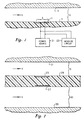
- Figure 1 is a schematic cross-sectional representation of a combination heat source/temperature sensor for use in the invention
- Figure 2 is a schematic cross-sectional representation of an embodiment of the invention
- Figure 3 is a schematic cross-sectional representation of a second embodiment of the invention
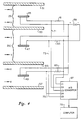
- Figure 4 is a schematic cross-sectional representation of a third embodiment of the invention
- Figure 5 is a schematic view illustrating in exploded form the heat source/sensor for use in the invention.
- FIG 1 shows a combination heat source/ temperature sensor 11 which has an effective radiating area A and is mounted in an insulator 13.
- sensor 11 has a thin layer or substrate 17 of material such as Kapton.
- the substrate 17 is coated or clad with a layer of temperature sensitive conductive metal 15, such as nickel.
- the layer 15 is etched into a sinuous coil pattern in order to develop the desired value of nominal resistance. Sensors of this general type are commercially available.
- a heat sink 19 is mounted directly across from sensor 11 at a predetermined gap or distance G.
- Heat sink 19 is a metal member that readily conducts heat, and thus attracts and absorbs the heat generated from sensor 11.
- the surface of the heat sink 19 is parallel with the surface of sensor 11.
- a measuring circuit 23 measures the power supplied to the sensor 11.
- the measuring circuit 23 also measures the resistance of sensor 11 in a conventional manner.
- the sensor 11 has a resistance which will increase with the increase in temperature. Consequently, a comparison of the resistance at ambient and at an elevated temperature will provide an indication of how much the temperature of the sensor 11 rises above the ambient temperature.
- the heat generated by the sensor 11 creates a thermal flux which flows directly from the sensor 11 to the heat sink 19.
- the space between the heat sink 19 and the sensor 11 is unobstructed so as to avoid impeding thermal flux flow.
- This thermal flux is modulated by the flowing fluid.
- the increase above ambient of the temperature of the sensor 11 and the power supplied to the sensor 11 can be used to compute the velocity V of the flowing fluid.
- TR @ V O fpm will be 30.99 degrees F.
- TR @ V O.1 fpm will be 21.23 degrees F.
- TR @ V 20 fpm will be 0.7 degrees F.
- V (K/CONSTANT2*C*D)*[LN((CONSTANT1*G*W/K*A*TR))/G]SQUARED
- the actual performance of the thermal flux mass flowmeter illustrated in Figure 1 differs somewhat at very high and very low velocities from that predicted by the above analysis.
- One difference is that the fluid velocity profile within the active gap G is not actually constant but is in fact dependent on the velocity and viscosity of the flowing fluids.
- the lines of thermal flux are in fact perpendicular to the sensor 11 and heat sink 19 only at the exact centre of the sensor 11. This has the effect of making the effective radiating area A also function of fluid velocity V rather than constant as assumed in the above analysis.
- two sensors 25, 27 are utilized, both of the same type as sensor 11 of the first embodiment. Both are active sensors in that both generate heat when supplied with power. Sensors 25, 27 are mounted on opposite sides of an insulator 29. Insulator 29 serves as isolation means for isolating each sensor 25, 27 from the heat generated by the other. Sensor 25 is spaced from a heat sink 31 by a gap G. Sensor 27 is considered a compensating sensor and is spaced from another heat sink 33 by a gap GC. Both gaps G and GC are unobstructed so as to allow a thermal flux to flow directly from each sensor 25, 27 to the respective heat sink 31, 33.
- the gap GC between the sensor 27 and the heat sink 33 is different from the gap G between the sensor 25 and heat sink 31.
- TR TRC (CONSTANT1*G*W/K*A)*EXP(-G*SQRT(CONSTANT2*C*D*V/K) (CONSTANT1*GC*WC/K*A)*EXP(-GC*SQRT(CONSTANT2*C*D*V/K)
- FIG. 3 illustrates how to minimize spurious heat losses from the second embodiment shown in Figure 2.
- the insulator 29 has now been discarded.
- Two identical sensors 35, 37 will be used, each identical to the sensors 25, 27 of Figure 2.
- Three parallel heat sinks 39, 41 and 43 are utilized. Both sensors 35, 37 are active in that both generate heat, but sensor 37 will be considered a compensating sensor. Active sensor 35 may be located equidistant between the two heat sinks 39, 41.
- Compensating sensor 37 may be located equidistant between the two heat sinks 41, 43.
- the heat sink 41 serves also as isolating means for isolating the sensors 35, 37 from the heat generated by each other.
- the gap 2G between the heat sinks 39, 41 differs from the gap 2GC between the heat sinks 41, 43.
- a further embodiment, shown in Figure 4, illustrates how to compensate for the varying temperatures of the fluid entering the thermal flux mass flowmeter.
- a pair of active sensors 45, 47 are utilized in the same manner as the sensors 35, 37 of Figure 3. Both are active, but sensor 47 will be considered a compensating sensor.
- a reference sensor 49 will be utilized.
- the reference sensor 49 has thermal properties identical to the active sensors 45, 47, but the power supplied to the reference sensor 49 is much less than that supplied to each of the active sensors 45, 47. Preferably the power is about one hundredth of that supplied to each of the active sensors 45, 47.
- the reference sensor 49 is employed for measuring the ambient temperature of the flowing fluid.
- Active sensor 45 is located between heat sinks 51, 53.
- Compensating active sensor 47 is located between heat sinks 53, 55.
- the gap 2G separating the heat sinks 51, 53 differs from the gap 2GC separating the heat sinks 53, 55.
- the reference sensor 49 is isolated from any heat generated by the active sensors 45, 47. Likewise, each sensor 45, 47 is isolated from any heat generated by the other. Because of the low power supplied to the reference sensor 49, its resistance will be directly proportional to the temperature of the flowing fluid.
- the calculation of the apparent velocity V in this configuration remains the same as before, except that the temperature rise TR is now equal to the temperature of the primary active sensor 45 less the temperature of the reference sensor 49.
- the compensated temperature rise TRC is now equal to the temperature of the compensating active sensor 47 less the temperature of the reference sensor 49.
- a battery 59 or DC power source will have its positive lead connected to one side of each of the sensors 45, 47 or 49.
- Each active sensor 45, 47 has its other side connected respectively to identical resistors 61, 63. In one embodiment, these resistors 61, 63 were chosen to be 20 ohms.
- the reference sensor 49 has its other side connected to a third resistor 65. In one embodiment, resistor 65 is chosen to be 390 ohms.
- the opposite sides of the resistors 61, 63 and 65 are connected to negative side of the power source 59.
- the negative side of the power source 59 is also connected to a terminal C1 of a conventional analog voltage-to-digital data acquisition system or converter 67.
- the terminal C2 of the A/D converter 67 is connected to the junction of resistor 61 and primary active sensor 45.
- the terminal C3 is connected to the positive side of battery 59.
- the terminal C4 is connected to the junction of resistor 65 and reference sensor 49.
- the terminal C5 is connected to the junction of resistor 63 and the compensating active sensor 47.
- the A/D converter 67 is connected to a conventional computer 75.
- the A/D converter 67 collects the analog voltages at its terminal C1, C2, C3, C4 and C5 and supplies these measurements to the computer 75 as digital data and volts for calculating the apparent velocity V.
- the computer has programmed into it the various constants and fluid properties listed above.
- the computer has been programmed to compute the velocity based on the formula above.
- the resulting output velocities were found to have significant improved linearity in the extreme intervals from 1 to 10 fpm and 1000 to 10,000 fpm in the case of air. In the case of water, significant improvements were found in the ranges of .01 to .1 fpm and 3 to 30 fpm.
- the linearity at high and low fluid velocities has significantly improved due to the reduction of the effects of thermal flux distortion and fluid viscosity.
- the velocity of homogeneous mixtures of varying fluid types can now be accurately measured simply by applying a weighting factor representative of the average thermal properties of the mixture to the velocity calculation.
- the performance can be improved even further by utilizing for G and GC values which reflect the active effective gaps. These are gaps which one would use if the fluid velocity profile were in fact uniform.
Landscapes
- Physics & Mathematics (AREA)
- General Physics & Mathematics (AREA)
- Fluid Mechanics (AREA)
- Engineering & Computer Science (AREA)
- Aviation & Aerospace Engineering (AREA)
- Details Of Flowmeters (AREA)
- Measuring Volume Flow (AREA)
- Investigating Or Analyzing Materials Using Thermal Means (AREA)
Claims (12)
- Durchflußmesser zum Messen der Geschwindigkeit eines Strömungsmittels,
dadurch gekennzeichnet,
daß es in Kombination umfaßt:a. erste und zweite Sensoren (25, 27), die dazu ausgebildet sind, in Berührung mit dem Strömungsmittel angeordnet zu werden, wobei die Sensoren (25, 27) bei Speisung mit Energie Wärme erzeugen können;b. eine erste Wärmesenke (31), ausgebildet zur Anordnung in Berührung mit dem Strömungsmittel einen ersten Spalt (G) vom ersten Sensor (25) entfernt in einer Richtung, die im wesentlichen senkrecht zu der Strömungsrichtung verläuft;c. eine zweite Wärmesenke (33), ausgebildet zur Berührung mit dem Strömungsmittel einen zweiten Spalt (GC) vom zweiten Sensor (27) entfernt in einer Richtung, die im wesentlichen senkrecht zur Strömungsrichtung verläuft, wobei die Abmessung des zweiten Spalts (GC) unterschiedlich von der Abmessung des ersten Spalts (G) ist;d. Mittel (21) zum Zuführen von Energie an die Sensoren (25, 27) zum Erzeugen eines Wärmestroms, der über den Spalt von dem ersten Sensor (25) zu der ersten Wärmesenke (31) fließen soll und zum Erzeugen eines Wärmestroms, der von dem zweiten Sensor (27) über den zweiten Spalt (GC) zu der zweiten Wärmesenke (33) fließen soll; unde. Mittel zum Messen des Temperaturanstiegs eines jeden der Sensoren (25, 27) über die Umgebungstemperatur des Strömungsmittels und zur Berechnung der Geschwindigkeit des Strömungsmittels aus den jeweiligen Temperaturanstiegen und der einem jeden Sensor (25, 27) zugeführten Energie. - Durchflußmesser nach Anspruch 1,
dadurch gekennzeichnet,
daß es umfaßt:a. erste und zweite Sensoren (35, 37), wobei die Sensoren bei Speisung mit Energie Wärme erzeugen können, und erste und zweite Wärmesenken (39, 41), welche durch einen ersten Spalt (2G) getrennt sind, wobei der erste Sensor (35) zwischen ihnen angeordnet ist;b. eine dritte Wärmesenke (43) ausgebildet zur Anordnung in Berührung mit dem Strömungsmittel und auf der der zweiten Wärmesenke (41) gegenüberliegenden Seite des zweiten Sensors (37), wobei der zweite Sensor zwischen der zweiten und dritten Wärmesenke (41, 43) angeordnet ist und die zweite und dritte Wärmesenke durch einen zweiten Spalt (2GC) getrennt sind, wobei die Abmessung des zweiten Spalts (2GC) unterschiedlich von der Abmessung des ersten Spalts (2G) ist;c. Mittel zum Zuführen von Energie an die Sensoren (35, 37) zum Erzeugen eines Wärmestroms, der vom ersten Sensor (35) zur ersten und zweiten Wärmesenke (39, 41) fließen soll und zum Erzeugen eines Wärmestroms, der vom zweiten Sensor (37) zu der zweiten und dritten Wärmesenke (41, 43) fließen soll; undd. Mittel zum Bestimmen des Temperaturanstiegs eines jeden der Sensoren (35, 37) über die Umgebungstemperatur des Strömungsmittels durch Messen der Widerstände der Sensoren (35, 37), wenn den Sensoren Energie zugeführt wird und durch Abziehen der jeweiligen Widerstandswerte bei Umgebungstemperatur von diesen Meßwerten, Mittel zum Teilen des Temperaturanstiegs des einen der Sensoren (35 oder 37) durch den Temperaturanstieg des anderen der Sensoren (37 oder 35) zum Bestimmen eines Verhältnisses und Mittel zur Berechnung der Geschwindigkeit des Strömungsmittels aus diesem Verhältnis und der jedem Sensor (35, 37) zugeführten Energie. - Durchflußmesser nach Anspruch 1,
dadurch gekennzeichnet,
daß er umfaßt:a. einen aktiven Sensor (45), einen kompensierenden Sensor (47) und einen Bezugssensor (49), wobei die Sensoren ausgebildet sind zum Erzeugen von Wärme bei Speisung mit Energie;b. erste, zweite und dritte Wärmesenken (51, 53, 55), wobei die erste Wärmesenke (51) in einem gewählten Abstand vom aktiven Sensor (45) angeordnet ist, die zweite Wärmesenke (53) in einem gewählten unterschiedlichen Abstand vom kompensierenden Sensor (47) und die dritte Wärmesenke in einem dritten gewählten Abstand vom Bezugssensor (49);c. Mittel (59) zum Zuführen von Energie an den aktiven und den kompensierenden Sensor (45, 47) zum Erzeugen eines Wärmestroms, der von dem genannten aktiven Sensor (45) zu der genannten ersten Wärmesenke (51) fließen soll, und zur Erzeugung eines Wärmestroms, der von dem genannten kompensierenden Sensor (47) zu der genannten zweiten Wärmesenke (53) fließen soll, und zum Zuführen von Energie an den Bezugssensor (49) auf einem Niveau, das wesentlich niedriger liegt als die Energie, die dem genannten aktiven und kompensierenden Sensor (45, 49) zugeführt wird; undd. Mittel zum Bestimmen der Temperaturanstiege des aktiven und kompensierenden Sensors (45, 47) über Umgebungstemperatur, durch Abziehen der gemessenen Temperatur des genannten Bezugssensors (49) von der gemessenen Temperatur der genannten Sensoren (45 und 47), und zum Bestimmen der Energie, die jedem der genannten Sensoren (45, 47 und 49) zugeführt wird und Berechnungsmittel (75) zur Berechnung der Geschwindigkeit des Strömungsmittels aus den genannten Meßwerten. - Durchflußmesser nach Anspruch 3,
dadurch gekennzeichnet,
daß die Berechnungsmittel (75) zur Bildung eines Verhältnisses der genannten Temperaturanstiege über die Umgebungstemperatur der genannten aktiven und kompensierenden Sensoren (45 und 47) ausgebildet sind und zum Berechnen der Geschwindigkeit des Strömungsmittels aus diesem Verhältnis und der jedem der genannten Sensoren (45, 47 und 49) zugeführten Energie. - Durchflußmesser nach einem der Ansprüche 3 oder 4,
dadurch gekennzeichnet,
daß er weiterhin umfaßt eine erste Wärmesenke (57), die zur Anordnung in Berührung mit dem Strömungsmittel ausgebildet ist, wobei jeder der Sensoren (45, 47, 49) zwischen zwei der Wärmesenken angeordnet und von den anderen Sensoren getrennt ist durch mindestens eine der Wärmesenken, wobei der aktive Sensor (45) zwischen zwei der Wärmesenken (51, 53) angeordnet ist, welche voneinander getrennt sind durch einen gewählten ersten Spalt (2G), wobei der kompensierende Sensor (47) zwischen zwei der Wärmesenken (53, 55) angeordnet ist, welche voneinander getrennt sind durch einen ausgewählten zweiten Spalt (2GC), der sich von dem ersten Spalt (2G) unterscheidet und wobei der Bezugssensor (49) zwischen zwei der Wärmesenken (55, 57) angeordnet ist;
und dadurch, daß die Mittel (59) ausgebildet sind zum Zuführen elektrischer Energie an den aktiven und kompensierenden Sensor (45, 47) derart, daß ein Wärmestrom veranlaßt wird, von dem aktiven Sensor (45) zu den benachbart zu dem aktiven Sensor angeordneten Wärmesenken (51, 53) zu fließen und daß ein Wärmestrom veranlaßt wird, von dem kompensierenden Sensor (47) zu den benachbart zum kompensierenden Sensor (47) angeordneten Wärmesenken (53, 55) zu fließen und zum Zuführen elektrischer Energie an den Referenzsensor (59) auf einem wesentlich niedrigeren Niveau als die dem aktiven und dem kompensierenden Sensor (45, 47) zugeführte Energie. - Durchflußmesser nach einem der Ansprüche 3 oder 4,
dadurch gekennzeichnet,
daß die Berechnungsmittel (75) ausgebildet sind zum Bestimmen des Verhältnisses durch Teilen des Temperaturanstiegs über Umgebungstemperatur des aktiven Sensors (45) durch den Temperaturanstieg des kompensierenden Sensors (47) über Umgebungstemperatur. - Durchflußmesser nach Anspruch 3,
dadurch gekennzeichnet,
daß der Bezugssensor (49) mit gleichem Abstand zwischen zwei der Wärmesenken (51, 53, 55, 57) angeordnet ist. - Durchflußmesser nach einem der Ansprüche 1 bis 7,
dadurch gekennzeichnet,
daß er weiterhin Isoliermittel (9) für ein Isolieren eines Sensors von dem Wärmestrom des anderen Sensors umfaßt. - Durchflußmesser nach einem der Ansprüche 1 bis 8,
dadurch gekennzeichnet,
daß die Sensoren mit Abstand zueinander angeordnet sind in einer Richtung, welche im wesentlichen senkrecht zur Strömungsrichtung verläuft. - Durchflußmesser nach einem der Ansprüche 1 bis 9,
dadurch gekennzeichnet,
daß der Durchflußmesser zur Montage innerhalb einer Leitung ausgebildet ist, die eine Wand aufweist, und daß die Wand der Leitung mindestens eine der Wärmesenken bildet. - Verfahren zum Messen der Geschwindigkeit eines Strömungsmittelflusses unter Verwendung eines Durchflußmessers nach einem der vorhergehenden Ansprüche,
dadurch gekennzeichnet,
daß es umfaßt:a. Zufuhr elektrischer Energie zu den Sensoren (25, 27, 35, 37, 45, 47) des Durchflußmessers derart, daß ein Wärmestrom veranlaßt wird, von den Sensoren zu den benachbarten Wärmesenken (31, 33, 39, 41, 43, 51, 53, 55, 57) zu fließen, welcher Wärmestrom durch das Strömungsmittel verändert wird; undb. Messen des Temperaturanstiegs eines jeden Sensors über die Umgebungstemperatur des Strömungsmittels, wenn die genannte elektrische Energie zugeführt wird, und Berechnen der Strömungsmittelgeschwindigkeit aus dem genannten Temperaturanstieg und der genannten zugeführten elektrischen Energie. - Verfahren nach Anspruch 11,
dadurch gekennzeichnet,
daß der Durchflußmesser ein Durchflußmesser gemäß Anspruch 3 ist und die Berechnungsmittel (45) die Strömungsmittelgeschwindigkeit aufgrund der folgenden Gleichung berechnen: V = Geschwindigkeit des StrömungsmittelsK = thermische Leitfähigkeit des StrömungsmittelsKonstante 2 = eine Konstante, die von den Maßeinheiten abhängtC = thermische Kapazität oder spezifische Wärme des StrömungsmittelsD = Dichte des StrömungsmittelsG = Spaltabstand des ersten SensorsGC = Spaltabstand des zweiten SensorsWC = dem zweiten Sensor zugeführte EnergieW = dem ersten Sensor zugeführte EnergieTRC = Temperaturanstieg des ersten Sensors über Umgebungstemperatur des Strömungsmittels bei Zufuhr von Energie; undTR = Temperaturanstieg des ersten Sensors über Umgebungstemperatur des Strömungsmittels bei Zufuhr von Energie.
Applications Claiming Priority (2)
| Application Number | Priority Date | Filing Date | Title |
|---|---|---|---|
| US07/363,220 US4969357A (en) | 1988-06-27 | 1989-06-08 | Compensated thermal flux mass flowmeter |
| US363220 | 1989-06-08 |
Publications (3)
| Publication Number | Publication Date |
|---|---|
| EP0403142A2 EP0403142A2 (de) | 1990-12-19 |
| EP0403142A3 EP0403142A3 (de) | 1992-11-25 |
| EP0403142B1 true EP0403142B1 (de) | 1995-04-26 |
Family
ID=23429329
Family Applications (1)
| Application Number | Title | Priority Date | Filing Date |
|---|---|---|---|
| EP90306111A Expired - Lifetime EP0403142B1 (de) | 1989-06-08 | 1990-06-05 | Kompensierter Wärmeübergangsmassendurchflussmesser |
Country Status (8)
| Country | Link |
|---|---|
| US (1) | US4969357A (de) |
| EP (1) | EP0403142B1 (de) |
| JP (1) | JP2796174B2 (de) |
| AT (1) | ATE121845T1 (de) |
| CA (1) | CA2018272C (de) |
| DE (1) | DE69018880T2 (de) |
| DK (1) | DK0403142T3 (de) |
| ES (1) | ES2074127T3 (de) |
Families Citing this family (18)
| Publication number | Priority date | Publication date | Assignee | Title |
|---|---|---|---|---|
| US5419190A (en) * | 1992-08-03 | 1995-05-30 | Thermal Instrument Co. | Apparatus and method for measurement of mass flow rates in a large conduit |
| NL9201906A (nl) * | 1992-11-02 | 1994-06-01 | Huiberts Albertus T | Werkwijze en inrichting voor het meten van het debiet van een mediumstroom. |
| US5764539A (en) * | 1994-01-21 | 1998-06-09 | Novartis Nutrition Ag | Non-invasive system and method for a fluid flow monitoring system |
| US5525040A (en) * | 1994-03-31 | 1996-06-11 | B&B Financial Planning Inc. | Controller for oil wells with a thermal dispersion probe |
| US5984641A (en) * | 1997-05-05 | 1999-11-16 | 1273941 Ontario Inc. | Controller for oil wells using a heated probe sensor |
| US6447520B1 (en) * | 2001-03-19 | 2002-09-10 | Advanced Medical Optics, Inc. | IOL insertion apparatus with IOL engagement structure and method for using same |
| NL1017335C2 (nl) * | 2001-02-12 | 2002-08-13 | Tno | Werkwijze en inrichting voor het bepalen van een warmteoverdrachtcoÙfficiÙnt van een sensorsamenstel naar een flu´dum. |
| NL1017334C2 (nl) * | 2001-02-12 | 2002-08-13 | Tno | Werkwijze en inrichting voor het bepalen van een warmtestroom naar een flu´dum. |
| CA2437912A1 (en) * | 2001-03-26 | 2002-10-03 | Sit La Precisa S.P.A. | A device for measuring gas flow-rate, particularly for burners |
| US6796172B2 (en) * | 2002-07-31 | 2004-09-28 | Hewlett-Packard Development Company, L.P. | Flow sensor |
| US6871535B2 (en) | 2002-08-14 | 2005-03-29 | Hewlett-Packard Development Company, L.P. | Flow direction detector |
| US7481213B2 (en) * | 2004-02-11 | 2009-01-27 | Hewlett-Packard Development Company, L.P. | Medicament dispenser |
| US7467630B2 (en) * | 2004-02-11 | 2008-12-23 | Hewlett-Packard Development Company, L.P. | Medicament dispenser |
| US20060159091A1 (en) * | 2005-01-19 | 2006-07-20 | Arjen Boers | Active multicast information protocol |
| US7467545B2 (en) * | 2007-05-09 | 2008-12-23 | Yaron Ankori | Method and device for measuring water currents |
| US7860667B2 (en) * | 2008-10-03 | 2010-12-28 | Ruskin Company | Gas measurement system |
| US9568349B2 (en) | 2013-03-15 | 2017-02-14 | Ruskin Company | Gas flow measurement system and method of operation |
| CA3103598A1 (fr) | 2020-12-21 | 2022-06-21 | Federico Torriano | Debitmetre electronique a bilan thermique |
Family Cites Families (5)
| Publication number | Priority date | Publication date | Assignee | Title |
|---|---|---|---|---|
| JPS5752866A (en) * | 1980-09-13 | 1982-03-29 | Tokyo Keiso Kk | Flow speed measuring device |
| JPS5988622A (ja) * | 1982-11-12 | 1984-05-22 | Ohkura Electric Co Ltd | 熱式質量流量計 |
| US4691566A (en) * | 1984-12-07 | 1987-09-08 | Aine Harry E | Immersed thermal fluid flow sensor |
| US4790181A (en) * | 1983-12-01 | 1988-12-13 | Aine Harry E | Thermal mass flow meter and method of making same |
| US4735086A (en) * | 1987-06-26 | 1988-04-05 | Ford Motor Company | Thick film mass airflow meter with minimal thermal radiation loss |
-
1989
- 1989-06-08 US US07/363,220 patent/US4969357A/en not_active Expired - Fee Related
-
1990
- 1990-06-05 EP EP90306111A patent/EP0403142B1/de not_active Expired - Lifetime
- 1990-06-05 AT AT90306111T patent/ATE121845T1/de not_active IP Right Cessation
- 1990-06-05 DK DK90306111.7T patent/DK0403142T3/da active
- 1990-06-05 ES ES90306111T patent/ES2074127T3/es not_active Expired - Lifetime
- 1990-06-05 DE DE69018880T patent/DE69018880T2/de not_active Expired - Fee Related
- 1990-06-05 CA CA002018272A patent/CA2018272C/en not_active Expired - Fee Related
- 1990-06-06 JP JP2146399A patent/JP2796174B2/ja not_active Expired - Lifetime
Also Published As
| Publication number | Publication date |
|---|---|
| ATE121845T1 (de) | 1995-05-15 |
| JPH03103722A (ja) | 1991-04-30 |
| CA2018272C (en) | 1996-10-01 |
| EP0403142A3 (de) | 1992-11-25 |
| CA2018272A1 (en) | 1990-12-08 |
| EP0403142A2 (de) | 1990-12-19 |
| DK0403142T3 (da) | 1995-10-02 |
| ES2074127T3 (es) | 1995-09-01 |
| DE69018880D1 (de) | 1995-06-01 |
| US4969357A (en) | 1990-11-13 |
| JP2796174B2 (ja) | 1998-09-10 |
| DE69018880T2 (de) | 1995-09-21 |
Similar Documents
| Publication | Publication Date | Title |
|---|---|---|
| US4969357A (en) | Compensated thermal flux mass flowmeter | |
| JP3229168B2 (ja) | 流量検出装置 | |
| US6169965B1 (en) | Fluid property and flow sensing via a common frequency generator and FFT | |
| US3800592A (en) | Flowmeter | |
| US5463899A (en) | Simultaneous measurement of gas thermal conductivity and mass flow | |
| KR100326479B1 (ko) | 차동전류열질량유동변환기 | |
| CA2433159C (en) | Flow sensor | |
| CA2044655C (en) | Thermal type flowmeter | |
| US7000464B2 (en) | Measuring and control of low fluid flow rates with heated conduit walls | |
| US4494406A (en) | Means for measuring large area mass flow | |
| WO1989012803A1 (en) | Flow sensor | |
| Ferreira et al. | Hot-wire anemometer with temperature compensation using only one sensor | |
| CA1193471A (en) | Non-intrusive thermal power monitor and method | |
| Bruun | Hot-film anemometry in liquid flows | |
| US6668642B2 (en) | Apparatus and method for thermal isolation of thermal mass flow sensor | |
| EP0349174B1 (de) | Wärmefluss-Durchflussmesser | |
| Rehn et al. | Dual-element, solid-state fluid flow sensor | |
| CA1187719A (en) | Non-obstructive thermodynamic flow meter | |
| Sherif et al. | Temperature correction for the output response of a constant-temperature hot-film anemometer in nonisothermal flows with strong property-temperature dependence | |
| Sherif | On the propagation of random errors of constant-temperature anemometers in nonisothermal flows | |
| JPS61167820A (ja) | 流量検出器 | |
| KR100262225B1 (ko) | 유속측정회로 | |
| JPS61231415A (ja) | マスフロ−検出装置 | |
| SU1012101A1 (ru) | Тепловой газодинамический анализатор состава | |
| Harris | A cold tip velocity meter for the measurement of turbulence in water. Volumes 1 & 2. April 1967. |
Legal Events
| Date | Code | Title | Description |
|---|---|---|---|
| PUAI | Public reference made under article 153(3) epc to a published international application that has entered the european phase |
Free format text: ORIGINAL CODE: 0009012 |
|
| AK | Designated contracting states |
Kind code of ref document: A2 Designated state(s): AT BE CH DE DK ES FR GB GR IT LI LU NL SE |
|
| PUAL | Search report despatched |
Free format text: ORIGINAL CODE: 0009013 |
|
| AK | Designated contracting states |
Kind code of ref document: A3 Designated state(s): AT BE CH DE DK ES FR GB GR IT LI LU NL SE |
|
| 17P | Request for examination filed |
Effective date: 19930524 |
|
| 17Q | First examination report despatched |
Effective date: 19931124 |
|
| GRAA | (expected) grant |
Free format text: ORIGINAL CODE: 0009210 |
|
| RAP3 | Party data changed (applicant data changed or rights of an application transferred) |
Owner name: MICKLER, BRIAN ELLIS |
|
| AK | Designated contracting states |
Kind code of ref document: B1 Designated state(s): AT BE CH DE DK ES FR GB GR IT LI LU NL SE |
|
| PG25 | Lapsed in a contracting state [announced via postgrant information from national office to epo] |
Ref country code: GR Free format text: LAPSE BECAUSE OF FAILURE TO SUBMIT A TRANSLATION OF THE DESCRIPTION OR TO PAY THE FEE WITHIN THE PRESCRIBED TIME-LIMIT Effective date: 19950426 |
|
| REF | Corresponds to: |
Ref document number: 121845 Country of ref document: AT Date of ref document: 19950515 Kind code of ref document: T |
|
| REF | Corresponds to: |
Ref document number: 69018880 Country of ref document: DE Date of ref document: 19950601 |
|
| ITF | It: translation for a ep patent filed | ||
| ET | Fr: translation filed | ||
| REG | Reference to a national code |
Ref country code: ES Ref legal event code: FG2A Ref document number: 2074127 Country of ref document: ES Kind code of ref document: T3 |
|
| REG | Reference to a national code |
Ref country code: DK Ref legal event code: T3 |
|
| PLBE | No opposition filed within time limit |
Free format text: ORIGINAL CODE: 0009261 |
|
| STAA | Information on the status of an ep patent application or granted ep patent |
Free format text: STATUS: NO OPPOSITION FILED WITHIN TIME LIMIT |
|
| 26N | No opposition filed | ||
| PGFP | Annual fee paid to national office [announced via postgrant information from national office to epo] |
Ref country code: GB Payment date: 19990517 Year of fee payment: 10 |
|
| PGFP | Annual fee paid to national office [announced via postgrant information from national office to epo] |
Ref country code: FR Payment date: 19990610 Year of fee payment: 10 |
|
| PGFP | Annual fee paid to national office [announced via postgrant information from national office to epo] |
Ref country code: DK Payment date: 19990614 Year of fee payment: 10 Ref country code: DE Payment date: 19990614 Year of fee payment: 10 Ref country code: CH Payment date: 19990614 Year of fee payment: 10 Ref country code: AT Payment date: 19990614 Year of fee payment: 10 |
|
| PGFP | Annual fee paid to national office [announced via postgrant information from national office to epo] |
Ref country code: ES Payment date: 19990624 Year of fee payment: 10 |
|
| PGFP | Annual fee paid to national office [announced via postgrant information from national office to epo] |
Ref country code: SE Payment date: 19990628 Year of fee payment: 10 Ref country code: NL Payment date: 19990628 Year of fee payment: 10 |
|
| PGFP | Annual fee paid to national office [announced via postgrant information from national office to epo] |
Ref country code: LU Payment date: 19990702 Year of fee payment: 10 |
|
| PGFP | Annual fee paid to national office [announced via postgrant information from national office to epo] |
Ref country code: BE Payment date: 19990819 Year of fee payment: 10 |
|
| PG25 | Lapsed in a contracting state [announced via postgrant information from national office to epo] |
Ref country code: LU Free format text: LAPSE BECAUSE OF NON-PAYMENT OF DUE FEES Effective date: 20000605 Ref country code: GB Free format text: LAPSE BECAUSE OF NON-PAYMENT OF DUE FEES Effective date: 20000605 Ref country code: DK Free format text: LAPSE BECAUSE OF NON-PAYMENT OF DUE FEES Effective date: 20000605 Ref country code: AT Free format text: LAPSE BECAUSE OF NON-PAYMENT OF DUE FEES Effective date: 20000605 |
|
| PG25 | Lapsed in a contracting state [announced via postgrant information from national office to epo] |
Ref country code: SE Free format text: LAPSE BECAUSE OF NON-PAYMENT OF DUE FEES Effective date: 20000606 Ref country code: ES Free format text: THE PATENT HAS BEEN ANNULLED BY A DECISION OF A NATIONAL AUTHORITY Effective date: 20000606 |
|
| PG25 | Lapsed in a contracting state [announced via postgrant information from national office to epo] |
Ref country code: LI Free format text: LAPSE BECAUSE OF NON-PAYMENT OF DUE FEES Effective date: 20000630 Ref country code: CH Free format text: LAPSE BECAUSE OF NON-PAYMENT OF DUE FEES Effective date: 20000630 Ref country code: BE Free format text: LAPSE BECAUSE OF NON-PAYMENT OF DUE FEES Effective date: 20000630 |
|
| BERE | Be: lapsed |
Owner name: MICKLER BRIAN ELLIS Effective date: 20000630 |
|
| PG25 | Lapsed in a contracting state [announced via postgrant information from national office to epo] |
Ref country code: NL Free format text: LAPSE BECAUSE OF NON-PAYMENT OF DUE FEES Effective date: 20010101 |
|
| GBPC | Gb: european patent ceased through non-payment of renewal fee |
Effective date: 20000605 |
|
| REG | Reference to a national code |
Ref country code: CH Ref legal event code: PL |
|
| EUG | Se: european patent has lapsed |
Ref document number: 90306111.7 |
|
| PG25 | Lapsed in a contracting state [announced via postgrant information from national office to epo] |
Ref country code: FR Free format text: LAPSE BECAUSE OF NON-PAYMENT OF DUE FEES Effective date: 20010228 |
|
| NLV4 | Nl: lapsed or anulled due to non-payment of the annual fee |
Effective date: 20010101 |
|
| REG | Reference to a national code |
Ref country code: DK Ref legal event code: EBP |
|
| REG | Reference to a national code |
Ref country code: FR Ref legal event code: ST |
|
| PG25 | Lapsed in a contracting state [announced via postgrant information from national office to epo] |
Ref country code: DE Free format text: LAPSE BECAUSE OF NON-PAYMENT OF DUE FEES Effective date: 20010403 |
|
| REG | Reference to a national code |
Ref country code: ES Ref legal event code: FD2A Effective date: 20020204 |
|
| PG25 | Lapsed in a contracting state [announced via postgrant information from national office to epo] |
Ref country code: IT Free format text: LAPSE BECAUSE OF NON-PAYMENT OF DUE FEES Effective date: 20050605 |