EP0403076B1 - Magnetic medium for longitudinal recording - Google Patents
Magnetic medium for longitudinal recording Download PDFInfo
- Publication number
- EP0403076B1 EP0403076B1 EP90305149A EP90305149A EP0403076B1 EP 0403076 B1 EP0403076 B1 EP 0403076B1 EP 90305149 A EP90305149 A EP 90305149A EP 90305149 A EP90305149 A EP 90305149A EP 0403076 B1 EP0403076 B1 EP 0403076B1
- Authority
- EP
- European Patent Office
- Prior art keywords
- magnetic
- layer
- magnetic recording
- head
- magnetic layer
- Prior art date
- Legal status (The legal status is an assumption and is not a legal conclusion. Google has not performed a legal analysis and makes no representation as to the accuracy of the status listed.)
- Expired - Lifetime
Links
Images
Classifications
-
- G—PHYSICS
- G11—INFORMATION STORAGE
- G11B—INFORMATION STORAGE BASED ON RELATIVE MOVEMENT BETWEEN RECORD CARRIER AND TRANSDUCER
- G11B5/00—Recording by magnetisation or demagnetisation of a record carrier; Reproducing by magnetic means; Record carriers therefor
- G11B5/62—Record carriers characterised by the selection of the material
- G11B5/64—Record carriers characterised by the selection of the material comprising only the magnetic material without bonding agent
- G11B5/66—Record carriers characterised by the selection of the material comprising only the magnetic material without bonding agent the record carriers consisting of several layers
- G11B5/676—Record carriers characterised by the selection of the material comprising only the magnetic material without bonding agent the record carriers consisting of several layers having magnetic layers separated by a nonmagnetic layer, e.g. antiferromagnetic layer, Cu layer or coupling layer
-
- Y—GENERAL TAGGING OF NEW TECHNOLOGICAL DEVELOPMENTS; GENERAL TAGGING OF CROSS-SECTIONAL TECHNOLOGIES SPANNING OVER SEVERAL SECTIONS OF THE IPC; TECHNICAL SUBJECTS COVERED BY FORMER USPC CROSS-REFERENCE ART COLLECTIONS [XRACs] AND DIGESTS
- Y10—TECHNICAL SUBJECTS COVERED BY FORMER USPC
- Y10S—TECHNICAL SUBJECTS COVERED BY FORMER USPC CROSS-REFERENCE ART COLLECTIONS [XRACs] AND DIGESTS
- Y10S428/00—Stock material or miscellaneous articles
- Y10S428/90—Magnetic feature
-
- Y—GENERAL TAGGING OF NEW TECHNOLOGICAL DEVELOPMENTS; GENERAL TAGGING OF CROSS-SECTIONAL TECHNOLOGIES SPANNING OVER SEVERAL SECTIONS OF THE IPC; TECHNICAL SUBJECTS COVERED BY FORMER USPC CROSS-REFERENCE ART COLLECTIONS [XRACs] AND DIGESTS
- Y10—TECHNICAL SUBJECTS COVERED BY FORMER USPC
- Y10T—TECHNICAL SUBJECTS COVERED BY FORMER US CLASSIFICATION
- Y10T428/00—Stock material or miscellaneous articles
- Y10T428/12—All metal or with adjacent metals
- Y10T428/12465—All metal or with adjacent metals having magnetic properties, or preformed fiber orientation coordinate with shape
-
- Y—GENERAL TAGGING OF NEW TECHNOLOGICAL DEVELOPMENTS; GENERAL TAGGING OF CROSS-SECTIONAL TECHNOLOGIES SPANNING OVER SEVERAL SECTIONS OF THE IPC; TECHNICAL SUBJECTS COVERED BY FORMER USPC CROSS-REFERENCE ART COLLECTIONS [XRACs] AND DIGESTS
- Y10—TECHNICAL SUBJECTS COVERED BY FORMER USPC
- Y10T—TECHNICAL SUBJECTS COVERED BY FORMER US CLASSIFICATION
- Y10T428/00—Stock material or miscellaneous articles
- Y10T428/24—Structurally defined web or sheet [e.g., overall dimension, etc.]
- Y10T428/24942—Structurally defined web or sheet [e.g., overall dimension, etc.] including components having same physical characteristic in differing degree
- Y10T428/2495—Thickness [relative or absolute]
-
- Y—GENERAL TAGGING OF NEW TECHNOLOGICAL DEVELOPMENTS; GENERAL TAGGING OF CROSS-SECTIONAL TECHNOLOGIES SPANNING OVER SEVERAL SECTIONS OF THE IPC; TECHNICAL SUBJECTS COVERED BY FORMER USPC CROSS-REFERENCE ART COLLECTIONS [XRACs] AND DIGESTS
- Y10—TECHNICAL SUBJECTS COVERED BY FORMER USPC
- Y10T—TECHNICAL SUBJECTS COVERED BY FORMER US CLASSIFICATION
- Y10T428/00—Stock material or miscellaneous articles
- Y10T428/26—Web or sheet containing structurally defined element or component, the element or component having a specified physical dimension
- Y10T428/263—Coating layer not in excess of 5 mils thick or equivalent
- Y10T428/264—Up to 3 mils
- Y10T428/265—1 mil or less
Definitions
- This invention relates to a magnetic medium for longitudinal recording which suppresses off-track fringing signals.
- the present invention provides magnetic media and methods for the providing thereof according to the appendant claims.
- a magnetic medium for longitudinal recording includes a magnetic image layer cooperating with a hard magnetic recording layer.
- the layers may be separated by a nonmagnetic buffer layer.
- the image layer may be an underlayer.
- the magnetic thickness of the magnetic image layer be greater than the magnetic thickness of the hard magnetic recording layer.
- a suitable magnetic thickness for the magnetic image layer is approximately 30% thicker than the hard magnetic layer, where the magnetic thickness is equal to the product of the geometric thickness and the remanent magnetization.
- the nonmagnetic layer thickness be in the range of 0.5 to 2 times the effective fly height of the magnetic head.
- the magnetic image layer has low permeability to avoid shorting out the head poles which reduces head efficiency.
- the image layer in this aspect may also have high coercivity.
- the magnetic image layer has still lower permeability and higher coercivity so as to reduce the negative dip in the signal caused by the leading and trailing edges off the head.
- the head generates magnetic fields during read to saturate the magnetic image layer in the medium so as to cancel the effect of the image charges below the head. This technique will allow the use of very thin buffer layers and will facilitate using a two-pole head to read.
- a uniaxial anisotropy may be induced in a radial direction in the magnetic image layer of the medium of this invention.
- the uniaxial anisotropy may be induced by an applied magnetic field during deposition by annealing the medium in a magnetic field after deposition by controlling the angle of incidence during vacuum deposition, or by pretexturing the substrate on which the magnetic image layer is deposited.
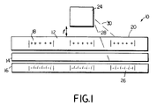
- Fig. 1 of the drawing is a cross-sectional view of the magnetic medium, and a head thereover.
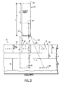
- Fig. 2 is an expanded diagram of the embodiment shown in Fig. 1.
- a magnetic medium 10 which includes a hard magnetic recording layer 12 of thickness (t m ), a nonmagnetic buffer layer 14 of thickness (t b ), and a magnetic image layer 16.
- a hard magnetic recording layer 12 of thickness (t m ) the hard magnetic recording layer 12 of thickness (t m )
- a nonmagnetic buffer layer 14 of thickness (t b ) the nonmagnetic buffer layer 14 of thickness (t b )
- a magnetic image layer 16 of thickness (t x )
- the magnetization of the hard magnetic layer 12 is treated as a series of discrete magnetic charges 18, 21 located at the center (t m /2) from either surface of the hard magnetic layer 12.
- These "actual charges" 18, 21 (+) located in the hard magnetic layer 12 behave as if they induce negative image charges 19, 26 (-) within the magnetic image layer 16.
- the magnetic image layer 16, located below the hard layer 12, is separated from the hard layer 12 by the nonmagnetic buffer layer 14.
- the distance from the actual charges 18, 21 to the surface 17 of the magnetic image layer layer 16 is (d) and is equal to (t m /2) (the distance into the hard layer 12 at which the actual charges are located) plus (t b ) (the thickness of the nonmagnetic buffer layer 14).
- the presence of charges in the hard layer 12, distance (d) away from the surface 17 of the magnetic image layer 16, induces the opposite image charges at the same distance (d) from the surface 17 into the image layer 16.
- charges in a track 20 adjacent to a track 22 beneath a head 24 can interfere with the ability of the head 24 to read the track 22 information accurately.
- the medium 10 is generally configured as a disk, and motion of the medium 10 is into or out of the plane of the figure.
- charges in the hard magnetic layer 12 at the track 20 induce negative image charges 26 in the magnetic image layer 16.
- the distance from the negative image charges 26 related to track 20 to the head 24 is only slightly greater than the distance to the head 24 from the related charges 18 in the hard magnetic layer 12. These distances are illustrated by the dashed lines 28 and 30, respectively.
- the signal from the magnetic image layer 16 image charges 26 is almost as strong as that from the actual charges 18 in hard layer 12 but opposite in sign. The two signals nearly cancel any effect on the adjacent track 22 which is being read by the head 24.
- the situation becomes very complex. This is the case because the head is made from a soft, or low coercivity, magnetic material and will have image charges induced in it.
- the head 24 flies above the surface 32 at an effective height (h) above the charges 21 in the hard magnetic layer 12.
- the presence of magnetic charges 21 in the hard magnetic layer 12 will induce almost equal and opposite image charges 25 in the head 24 at a distance (h) into the head 24 equal to the distance from the head surface 27 to the actual charges 21. Therefore, the image charges 25 in the head will be located at a distance (2h) from the actual charges 21.
- induced image charges 19 in the magnetic image layer 16 will induce a second set of image charges 29 in the head 24.
- Induced virtual charges 25, 29 in the head 24 in turn induce further virtual charges in the magnetic image layer 16 but not shown.
- the net effect of the new magnetic medium 10 is that off-track interference is reduced while the signal from the track of interest is only slightly affected.
- the suppression of low frequency signals is much greater than that of high frequency signals so the resolution (high frequency amplitude divided by low frequency amplitude) is also improved without resorting to electronic equalization which usually amplifies the noise as well.
- the thickness of the nonmagnetic buffer layer 14 may range from zero to roughly the distance of closest approach of the head to an adjacent track. Optimum performance under ordinary conditions will be obtained if the thickness of the nonmagnetic buffer layer ranges from 0.5 to two times the effective fly height. As the nonmagnetic layer is made thinner, off-track signal suppression increases but on-track high frequency amplitude decreases. An engineering tradeoff must be made between these two effects.
- the magnetic image layer 16 should be greater in magnetic thickness (geometric thickness x remanence) than that of the hard layer (e.g., 30% greater) so that it can absorb a substantial amount of the flux from the off-track signal without saturating. If it is made too thick, however, this layer suppresses the write process in proportion to its thickness.
- a two-pole head When a two-pole head is used to read (a three-pole head is preferred), two potential problems may arise.
- a first problem is that the pole corners will generate strong negative dips (e.g., 25% of the isolated signal for buffer thickness equal to effective fly height). This situation can be remedied either by electronic equalization or by beveling the pole corners so that the dips are softened.
- a second problem is that the magnetic image layer 16 may tend to short out the poles and reduce the head efficiency. To overcome this problem and reduce the negative dip problem, the permeability of the magnetic image layer 16 can be deliberately reduced. This will decrease the strength of the high order images but will also reduce the pole shorting effect.
- the magnetic properties of the magnetic image layer can be varied to both meet the requirements of the recording head in order to reduce the off track fringing and to reduce the dip caused by the trailing edge of the head.
- a hard layer has a permeability of about 1 and a coercivity of 1200 or greater; a semi-hard layer has a permeability of about 1 and a coercivity of between 64 and 500; a semi-soft layer has a permeability of about 20 and a coercivity of less than 2; and a soft layer has a permeability of about 1000 and a coercivity of less than 2.
- the effect of the image layer varies from cancelling all fringing but having a strong signal attenuation and inducing a strong negative trailing edge dip (in the case of a 2 pole head using a medium with soft-magnetic image layer) to allowing some fringing to occur but reducing the signal attenuation and the negative trailing edge dip (in the case of semi-hard magnetic image layer with a 2 pole head).
- the soft underlayer is preferred.
- a weak magnetic field may be applied to the medium during a read, at a strength large enough to saturate the magnetic image layer and so to cancel the effect of the image charges below the head, but not strong enough to affect the hard magnetic recording layer.
- This technique would allow the use of very thin buffer layers and would also help with the problems associated with using a two-pole head to read.
- the magnetic medium according to the invention is made by beginning with a polished Ni-P on aluminum standard substrate.
- a magnetic image layer such as NiFe is deposited on the substrate.
- the thickness of the magnetic image layer should be approximately 30% greater than the hard magnetic layer to be deposited later.
- a uniaxial anisotropy is induced in a radial direction (the medium will normally be disc-shaped) in the magnetic image layer by applying a field during deposit, by performing an anneal in a magnetic field later, by controlling the angle of incidence in the case of vacuum deposition or by pretexturing the substrate. If a soft magnetic image layer is desired then NiFe is deposited.
- a semi-soft magnetic image layer is desired (for two-pole head operation) then a high Hk alloy such as NiFeCo, NiCo, or CoZr is used. Finally, if a semi-hard magnetic image layer is desired, an alloy such as NiCoP is deposited.
- a nonmagnetic buffer layer (e.g., Ni-P for plating or Cr for sputtering) is next deposited.
- the thickness of this layer is in the range of 0.5 to two times the effective fly height.
- a hard longitudinal magnetic layer is then deposited by conventional means and finally an overcoat is deposited.
- the magnetic medium of the present invention reduces fringing at high track density and improves resolution.
- the fringing may be so strongly suppressed that the bottom pole can be made significantly oversized. In this way the need for on-wafer track trimming of the whole head is eliminated.
Landscapes
- Magnetic Record Carriers (AREA)
- Manufacturing Of Magnetic Record Carriers (AREA)
- Paints Or Removers (AREA)
- Magnetic Heads (AREA)
Abstract
Description
- This application corresponds to a continuation-in-part of application U.S.S.N. 103,965, filed October 5, 1987, which itself corresponds to PCT application WO89/03112.
- This invention relates to a magnetic medium for longitudinal recording which suppresses off-track fringing signals.
- As a recording head flies over a track of data, flux from this track and adjacent tracks is detected during a read operation. In many cases, adjacent tracks are separated by a wide enough intertrack space to make the flux reaching the head from an adjacent track insignificant compared to the flux from the track of interest. Adjacent track interference becomes more problematic when track density is high. In this latter case, the track adjacent to the track of interest is sufficiently close that its flux becomes significant.
- The present invention provides magnetic media and methods for the providing thereof according to the appendant claims.
- According to one aspect of the invention a magnetic medium for longitudinal recording includes a magnetic image layer cooperating with a hard magnetic recording layer. The layers may be separated by a nonmagnetic buffer layer. The image layer may be an underlayer.
- It is preferred that the magnetic thickness of the magnetic image layer be greater than the magnetic thickness of the hard magnetic recording layer. A suitable magnetic thickness for the magnetic image layer is approximately 30% thicker than the hard magnetic layer, where the magnetic thickness is equal to the product of the geometric thickness and the remanent magnetization. It is also preferred that the nonmagnetic layer thickness be in the range of 0.5 to 2 times the effective fly height of the magnetic head. In yet another aspect of the invention, the magnetic image layer has low permeability to avoid shorting out the head poles which reduces head efficiency. The image layer in this aspect may also have high coercivity.
- In still another aspect of the invention the magnetic image layer has still lower permeability and higher coercivity so as to reduce the negative dip in the signal caused by the leading and trailing edges off the head.
- In another aspect of the invention, the head generates magnetic fields during read to saturate the magnetic image layer in the medium so as to cancel the effect of the image charges below the head. This technique will allow the use of very thin buffer layers and will facilitate using a two-pole head to read.
- A uniaxial anisotropy may be induced in a radial direction in the magnetic image layer of the medium of this invention. The uniaxial anisotropy may be induced by an applied magnetic field during deposition by annealing the medium in a magnetic field after deposition by controlling the angle of incidence during vacuum deposition, or by pretexturing the substrate on which the magnetic image layer is deposited.
- Fig. 1 of the drawing is a cross-sectional view of the magnetic medium, and a head thereover.
- Fig. 2 is an expanded diagram of the embodiment shown in Fig. 1.
- In narrow track, high density magnetic readback systems, it is desirable to reduce fringing from tracks adjacent to a track being read. As shown in Figs. 1 and 2, this can be achieved in a
magnetic medium 10 which includes a hardmagnetic recording layer 12 of thickness (tm), anonmagnetic buffer layer 14 of thickness (tb), and amagnetic image layer 16. To understand the effect of themagnetic image layer 16 of thickness (tx), it is best to think in terms of the theory of virtual images. The magnetization of the hardmagnetic layer 12 is treated as a series of discretemagnetic charges magnetic layer 12. These "actual charges" 18, 21 (+) located in the hardmagnetic layer 12 behave as if they inducenegative image charges 19, 26 (-) within themagnetic image layer 16. - The
magnetic image layer 16, located below thehard layer 12, is separated from thehard layer 12 by thenonmagnetic buffer layer 14. The distance from theactual charges surface 17 of the magneticimage layer layer 16 is (d) and is equal to (tm/2) (the distance into thehard layer 12 at which the actual charges are located) plus (tb) (the thickness of the nonmagnetic buffer layer 14). The presence of charges in thehard layer 12, distance (d) away from thesurface 17 of themagnetic image layer 16, induces the opposite image charges at the same distance (d) from thesurface 17 into theimage layer 16. - In a conjunction with a conventional medium, charges in a
track 20 adjacent to atrack 22 beneath ahead 24 can interfere with the ability of thehead 24 to read thetrack 22 information accurately. (Themedium 10 is generally configured as a disk, and motion of themedium 10 is into or out of the plane of the figure.) As explained above, because of themagnetic image layer 16, charges in the hardmagnetic layer 12 at thetrack 20 inducenegative image charges 26 in themagnetic image layer 16. When the thicknesses of the layers 14 (tb) and 16 are small, the distance from the negative image charges 26 related totrack 20 to thehead 24 is only slightly greater than the distance to thehead 24 from therelated charges 18 in the hardmagnetic layer 12. These distances are illustrated by thedashed lines magnetic image layer 16image charges 26 is almost as strong as that from theactual charges 18 inhard layer 12 but opposite in sign. The two signals nearly cancel any effect on theadjacent track 22 which is being read by thehead 24. - When the
head 24 is directly above thetrack 22 of interest, the situation becomes very complex. This is the case because the head is made from a soft, or low coercivity, magnetic material and will have image charges induced in it. - Assume that the
head 24 flies above thesurface 32 at an effective height (h) above thecharges 21 in the hardmagnetic layer 12. The presence ofmagnetic charges 21 in the hardmagnetic layer 12 will induce almost equal and opposite image charges 25 in thehead 24 at a distance (h) into thehead 24 equal to the distance from thehead surface 27 to theactual charges 21. Therefore, the image charges 25 in the head will be located at a distance (2h) from theactual charges 21. - Further, induced
image charges 19 in themagnetic image layer 16 will induce a second set ofimage charges 29 in thehead 24. This second set ofhead image charges 29 will be nearly equal to and opposite the image charges in theimage layer 16, and located at a distance (n) into thehead 24 from thesurface 27 of thehead 24 where (n) is equal to the distance (g) fromsurface 27 to the image charges in themagnetic image layer 16, where g=h + 2d, from thesurface 27 of thehead 24. Inducedvirtual charges head 24 in turn induce further virtual charges in themagnetic image layer 16 but not shown. - Such inducing of image charges can go on indefinitely with each set of image charges inducing other image charges in its opposite magnetic material. The head thus sees an infinite series of repeating image charges similar in effect to the infinite series of images seen when one looks at the reflection of a mirror in another mirror. Although one would expect such an effect to result in cancellation of the signal from the track of interest, the applicant herein has determined this not to be the case. Analysis indicates only a weak suppression of the high frequency on-track signal (e.g., at 30 kfri, with an effective fly height of 0.25µm (10 microinches) and a
nonmagnetic buffer layer 14 thickness of 0.25µm (10 microinches), the loss of high frequency amplitude due to the buffer layer is about 12%). - The net effect of the new
magnetic medium 10 is that off-track interference is reduced while the signal from the track of interest is only slightly affected. The suppression of low frequency signals is much greater than that of high frequency signals so the resolution (high frequency amplitude divided by low frequency amplitude) is also improved without resorting to electronic equalization which usually amplifies the noise as well. - The thickness of the
nonmagnetic buffer layer 14 may range from zero to roughly the distance of closest approach of the head to an adjacent track. Optimum performance under ordinary conditions will be obtained if the thickness of the nonmagnetic buffer layer ranges from 0.5 to two times the effective fly height. As the nonmagnetic layer is made thinner, off-track signal suppression increases but on-track high frequency amplitude decreases. An engineering tradeoff must be made between these two effects. Themagnetic image layer 16 should be greater in magnetic thickness (geometric thickness x remanence) than that of the hard layer (e.g., 30% greater) so that it can absorb a substantial amount of the flux from the off-track signal without saturating. If it is made too thick, however, this layer suppresses the write process in proportion to its thickness. - When a two-pole head is used to read (a three-pole head is preferred), two potential problems may arise. A first problem is that the pole corners will generate strong negative dips (e.g., 25% of the isolated signal for buffer thickness equal to effective fly height). This situation can be remedied either by electronic equalization or by beveling the pole corners so that the dips are softened. A second problem is that the
magnetic image layer 16 may tend to short out the poles and reduce the head efficiency. To overcome this problem and reduce the negative dip problem, the permeability of themagnetic image layer 16 can be deliberately reduced. This will decrease the strength of the high order images but will also reduce the pole shorting effect. - The magnetic properties of the magnetic image layer can be varied to both meet the requirements of the recording head in order to reduce the off track fringing and to reduce the dip caused by the trailing edge of the head. Categorizing the combination of permeability (µ) and coercivity (Hc) of the magnetic image layer with reference to the "hardness" of the hard recording layer allows the following chart to be created, where permeability (µ) is equal to the ratio of the magnetic saturation field (Ms) to anistropy field (Hk), where MR is in Gauss, where Hc is in Oersteds (1 Oersted = 79.58 A/m) and where the values of Hc in the case of a semi-hard magnetic image layer is determinined by the formula:

- Here it will be appreciated that a hard layer has a permeability of about 1 and a coercivity of 1200 or greater; a semi-hard layer has a permeability of about 1 and a coercivity of between 64 and 500; a semi-soft layer has a permeability of about 20 and a coercivity of less than 2; and a soft layer has a permeability of about 1000 and a coercivity of less than 2.
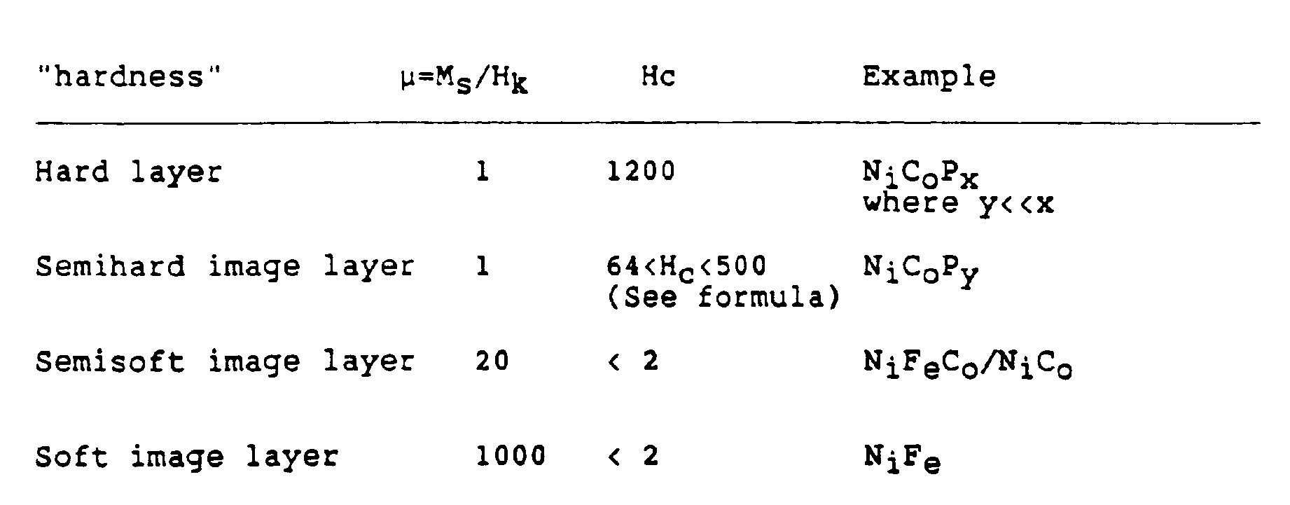
- As one moves down the chart, the effect of the image layer varies from cancelling all fringing but having a strong signal attenuation and inducing a strong negative trailing edge dip (in the case of a 2 pole head using a medium with soft-magnetic image layer) to allowing some fringing to occur but reducing the signal attenuation and the negative trailing edge dip (in the case of semi-hard magnetic image layer with a 2 pole head). With a 3 pole head, the soft underlayer is preferred.
- Finally, as another alternative, a weak magnetic field may be applied to the medium during a read, at a strength large enough to saturate the magnetic image layer and so to cancel the effect of the image charges below the head, but not strong enough to affect the hard magnetic recording layer. This technique would allow the use of very thin buffer layers and would also help with the problems associated with using a two-pole head to read.
- The magnetic medium according to the invention is made by beginning with a polished Ni-P on aluminum standard substrate. A magnetic image layer such as NiFe is deposited on the substrate. As stated above, the thickness of the magnetic image layer should be approximately 30% greater than the hard magnetic layer to be deposited later. A uniaxial anisotropy is induced in a radial direction (the medium will normally be disc-shaped) in the magnetic image layer by applying a field during deposit, by performing an anneal in a magnetic field later, by controlling the angle of incidence in the case of vacuum deposition or by pretexturing the substrate. If a soft magnetic image layer is desired then NiFe is deposited. If a semi-soft magnetic image layer is desired (for two-pole head operation) then a high Hk alloy such as NiFeCo, NiCo, or CoZr is used. Finally, if a semi-hard magnetic image layer is desired, an alloy such as NiCoP is deposited.
- A nonmagnetic buffer layer (e.g., Ni-P for plating or Cr for sputtering) is next deposited. The thickness of this layer is in the range of 0.5 to two times the effective fly height. A hard longitudinal magnetic layer is then deposited by conventional means and finally an overcoat is deposited.
- The magnetic medium of the present invention reduces fringing at high track density and improves resolution. When a three-pole head is used, the fringing may be so strongly suppressed that the bottom pole can be made significantly oversized. In this way the need for on-wafer track trimming of the whole head is eliminated.
- It is recognized that modifications and variations of the present invention will occur to those skilled in the art and it is intended that all such modifications and variations be included within the scope of the appended claims.
Claims (10)
- A magnetic medium comprising a magnetic recording layer, a second magnetic layer disposed beneath said magnetic recording layer and being magnetically soft relative to said magnetic recording layer, and a non-magnetic layer disposed between said magnetic recording layer and said second magnetic layer, characterized in that said second magnetic layer is semi-hard, having a magnetic field coercivity Hc between 64-500 oersteds (5093-39789 A/m).
- The medium of claim 1 wherein said second magnetic layer has a permeability of about 1.
- The medium of claim 1 wherein the second magnetic layer is NiCoP.
- A method for making a longitudinal recording medium comprising providing a first magnetic layer constructed to record information in a longitudinal direction therein depositing a non-magnetic layer on said first magnetic layer, and depositing a second magnetic layer on said non-magnetic layer, characterized in that said second magnetic layer is semi-hard having a magnetic field strength coercivity between 64-500 oersteds (5093-39789 A/m).
- The method of claim 4, wherein the permeability of said second magnetic layer is about 1.
- The method of claim 5, wherein said second magnetic layer is NiCoP.
- Magnetic recording apparatus comprising a magnetic recording head and a magnetic recording medium, said magnetic recording head adapted to operate at an effective flying height (h) over said magnetic recording medium, the magnetic recording medium comprising:
a magnetic recording layer;
a second magnetic layer disposed beneath said magnetic recording layer and being magnetically soft relative to said magnetic recording layer; and
a non-magnetic layer disposed between said magnetic recording layer and said second magnetic layer;
characterized in that:
said magnetic recording layer has a geometric thickness (tm) and a magnetic remanence (MR) and said second magnetic layer is semi-hard, having a magnetic field strength HC such that it meets the relationship:
- Magnetic recording apparatus as claimed in claim 7 in which Hc ranges between approximately 64 oersteds and 500 oersteds (5093-39789 A/m).
- Magnetic recording apparatus as claimed in claim 8 in which the permeability of said second magnetic layer is about 1.
- Magnetic recording apparatus as claimed in claim 9 wherein said second magnetic layer is NiCoP.
Applications Claiming Priority (2)
| Application Number | Priority Date | Filing Date | Title |
|---|---|---|---|
| US07/364,900 US5176965A (en) | 1987-10-05 | 1989-06-12 | Magnetic medium for longitudinal recording |
| US364900 | 1989-06-12 |
Publications (3)
| Publication Number | Publication Date |
|---|---|
| EP0403076A2 EP0403076A2 (en) | 1990-12-19 |
| EP0403076A3 EP0403076A3 (en) | 1991-07-03 |
| EP0403076B1 true EP0403076B1 (en) | 1995-10-25 |
Family
ID=23436583
Family Applications (1)
| Application Number | Title | Priority Date | Filing Date |
|---|---|---|---|
| EP90305149A Expired - Lifetime EP0403076B1 (en) | 1989-06-12 | 1990-05-14 | Magnetic medium for longitudinal recording |
Country Status (5)
| Country | Link |
|---|---|
| US (2) | US5176965A (en) |
| EP (1) | EP0403076B1 (en) |
| JP (1) | JPH0775070B2 (en) |
| AT (1) | ATE129590T1 (en) |
| DE (1) | DE69023170T2 (en) |
Families Citing this family (18)
| Publication number | Priority date | Publication date | Assignee | Title |
|---|---|---|---|---|
| US5587235A (en) * | 1993-02-19 | 1996-12-24 | Hitachi, Ltd. | Magnetic recording medium and magnetic recording apparatus |
| US5851643A (en) * | 1993-11-11 | 1998-12-22 | Hitachi, Ltd. | Magnetic recording media and magnetic recording read-back system which uses such media |
| US5750270A (en) * | 1995-02-07 | 1998-05-12 | Conner Peripherals, Inc. | Multi-layer magnetic recording media |
| US5830590A (en) * | 1996-06-28 | 1998-11-03 | Ampex Corporation | Magnetic storage and reproducing system with a low permeability keeper and a self-biased magnetoresistive reproduce head |
| US5861220A (en) * | 1996-08-06 | 1999-01-19 | Ampex Corporation | Method and apparatus for providing a magnetic storage and reproducing media with a keeper layer having a longitudinal anisotropy |
| US5843565A (en) * | 1996-10-31 | 1998-12-01 | Ampex Corporation | Particulate magnetic medium utilizing keeper technology and methods of manufacture |
| US6031682A (en) * | 1997-07-14 | 2000-02-29 | Iomega Corporation | Track trimming and orthogonal recording for cartridge tape |
| US6495252B1 (en) * | 1999-07-22 | 2002-12-17 | Seagate Technology Llc | Magnetic recording medium with superparamagnetic underlayer |
| JP2002288817A (en) * | 2001-03-26 | 2002-10-04 | Fuji Photo Film Co Ltd | Magnetic recording medium |
| US6842313B1 (en) | 2002-04-08 | 2005-01-11 | Maxtor Corporation | Floating down stream perpendicular write head shield |
| US7075756B1 (en) | 2002-11-07 | 2006-07-11 | Maxtor Corporation | Shielded pole writer |
| US7149045B1 (en) | 2002-11-07 | 2006-12-12 | Maxtor Corporation | Longitudinal media with soft underlayer and perpendicular write head |
| US7729092B1 (en) | 2002-11-07 | 2010-06-01 | Seagate Technology Llc | Shielded pole writer under reader |
| US7189583B2 (en) * | 2003-07-02 | 2007-03-13 | Micron Technology, Inc. | Method for production of MRAM elements |
| US7092209B2 (en) * | 2004-03-01 | 2006-08-15 | Hitachi Global Storage Technologies Netherlands B.V. | Longitudinal magnetic recording using magnetic media with a soft underlayer |
| US7927724B2 (en) | 2004-05-28 | 2011-04-19 | Hitachi Global Storage Technologies Netherlands B.V. | Magnetic recording media with orthogonal anisotropy enhancement or bias layer |
| US7425377B2 (en) * | 2005-02-04 | 2008-09-16 | Hitachi Global Storage Technologies Netherlands B.V. | Incoherently-reversing magnetic laminate with exchange coupled ferromagnetic layers |
| JP4113879B2 (en) * | 2005-02-04 | 2008-07-09 | Tdk株式会社 | Perpendicular magnetic recording head and magnetic recording apparatus |
Family Cites Families (25)
| Publication number | Priority date | Publication date | Assignee | Title |
|---|---|---|---|---|
| DE1153069B (en) * | 1960-02-06 | 1963-08-22 | Grundig Max | Arrangement for recording any signals with a transverse magnetization magnetic head |
| US3393982A (en) * | 1962-11-08 | 1968-07-23 | Ncr Co | Ferromagnetic storage devices having uniaxial anisotropy |
| FR1438563A (en) * | 1965-04-02 | 1966-05-13 | Bull General Electric | Improvements to coupled ferromagnetic blades or layers |
| FR2428886A1 (en) * | 1978-06-13 | 1980-01-11 | Cii Honeywell Bull | MAGNETIC INFORMATION MEDIUM WITH PERPENDICULAR RECORDING |
| JPS5771518A (en) * | 1980-10-22 | 1982-05-04 | Dainippon Printing Co Ltd | Magnetic recording medium |
| JPS5864634A (en) * | 1981-10-13 | 1983-04-18 | Hitachi Maxell Ltd | Magnetic recording medium |
| JPS58129032A (en) * | 1982-01-28 | 1983-08-01 | Toyo Tire & Rubber Co Ltd | Composition for pneumatic tire |
| US4621030A (en) * | 1982-07-19 | 1986-11-04 | Hitachi, Ltd. | Perpendicular magnetic recording medium and manufacturing method thereof |
| JPS5972644A (en) * | 1982-10-19 | 1984-04-24 | Nec Corp | Magnetic double layer recording medium |
| JPH061729B2 (en) * | 1983-01-17 | 1994-01-05 | 株式会社日立製作所 | Magnetic film and magnetic head using the same |
| JPS6052919A (en) * | 1983-09-01 | 1985-03-26 | Nec Corp | Vertical magnetic recording medium and its production |
| US4687712A (en) * | 1983-12-12 | 1987-08-18 | Matsushita Electric Industrial Co., Ltd. | Vertical magnetic recording medium |
| JPH0622170B2 (en) * | 1983-12-16 | 1994-03-23 | 株式会社日立製作所 | Magnetic head |
| DE3346876A1 (en) * | 1983-12-23 | 1985-07-11 | Siemens AG, 1000 Berlin und 8000 München | COMBINED WRITING AND READING MAGNET HEAD FOR THE UPPER MAGNETIZATION OF AN APPROPRIATE RECORDING MEDIA |
| DE3566848D1 (en) * | 1984-05-04 | 1989-01-19 | Siemens Ag | Thin-layer double-gap magnetic head for a perpendicularly magnetized recording medium |
| JPS6199932A (en) * | 1984-10-19 | 1986-05-19 | Sony Corp | Production of vertical magnetic recording medium |
| GB2175400B (en) * | 1984-10-31 | 1989-07-19 | Unilever Plc | Apparatus for use in electrical,e.g.electrochemical,measurement procedures,and its production and use,and composite assemblies incorporating the apparatus |
| US4656546A (en) * | 1985-01-22 | 1987-04-07 | Digital Equipment Corporation | Vertical magnetic recording arrangement |
| JPS61177633A (en) * | 1985-01-31 | 1986-08-09 | Fujitsu Ltd | Production of vertical magnetic recording medium |
| JPS61187125A (en) * | 1985-02-14 | 1986-08-20 | Hitachi Ltd | Magnetic field orientation method for magnetic disks |
| US4729805A (en) * | 1985-03-14 | 1988-03-08 | Minnesota Mining And Manufacturing Company | Recording medium annealing process |
| US4677032A (en) * | 1985-09-23 | 1987-06-30 | International Business Machines Corporation | Vertical magnetic recording media with multilayered magnetic film structure |
| US4735840A (en) * | 1985-11-12 | 1988-04-05 | Cyberdisk, Inc. | Magnetic recording disk and sputtering process and apparatus for producing same |
| JPS62204429A (en) * | 1986-03-04 | 1987-09-09 | Nippon Hoso Kyokai <Nhk> | Magnetic recording medium and magnetic head |
| JPH01503262A (en) * | 1987-10-05 | 1989-11-02 | ディジタル イクイプメント コーポレーション | Magnetic recording media for longitudinal recording |
-
1989
- 1989-06-12 US US07/364,900 patent/US5176965A/en not_active Expired - Lifetime
-
1990
- 1990-05-14 AT AT90305149T patent/ATE129590T1/en active
- 1990-05-14 EP EP90305149A patent/EP0403076B1/en not_active Expired - Lifetime
- 1990-05-14 DE DE69023170T patent/DE69023170T2/en not_active Expired - Fee Related
- 1990-06-11 JP JP2152520A patent/JPH0775070B2/en not_active Expired - Lifetime
-
1992
- 1992-09-16 US US07/945,706 patent/US5431969A/en not_active Expired - Lifetime
Also Published As
| Publication number | Publication date |
|---|---|
| US5176965A (en) | 1993-01-05 |
| DE69023170D1 (en) | 1995-11-30 |
| ATE129590T1 (en) | 1995-11-15 |
| JPH0775070B2 (en) | 1995-08-09 |
| DE69023170T2 (en) | 1996-04-18 |
| EP0403076A3 (en) | 1991-07-03 |
| US5431969A (en) | 1995-07-11 |
| JPH0363932A (en) | 1991-03-19 |
| EP0403076A2 (en) | 1990-12-19 |
Similar Documents
| Publication | Publication Date | Title |
|---|---|---|
| US5176965A (en) | Magnetic medium for longitudinal recording | |
| EP0400970B1 (en) | Perpendicular magnetic recording medium and production method thereof | |
| US4814921A (en) | Multilayered magnetic films and thin-film magnetic heads using the same as a pole | |
| US7378164B1 (en) | Soft underlayer structure for magnetic recording | |
| EP0301823A2 (en) | Three-pole magnetic recording head | |
| US6660357B1 (en) | Perpendicular magnetic recording media with laminated soft magnetic underlayer | |
| KR20050002805A (en) | Anti-ferromagnetically coupled perpendicular magnetic recording media | |
| US5103553A (en) | Method of making a magnetic recording head | |
| US6645647B1 (en) | Magnetic recording media including magnetically soft composite layer and method of making same | |
| JPH07503337A (en) | Magnetic recording media using soft magnetic materials | |
| EP0333843B1 (en) | Magnetic medium for longitudinal recording | |
| JPS61258323A (en) | Magneto-resistance effect head | |
| JPH08221734A (en) | Magnetic recording medium and magnetic recording device | |
| JPS63166008A (en) | Magnetic anisotropic recording medium | |
| US7092209B2 (en) | Longitudinal magnetic recording using magnetic media with a soft underlayer | |
| JP3222141B2 (en) | Magnetic recording medium and magnetic storage device | |
| JPH0916905A (en) | Thin-film magnetic transducer | |
| JP2000222715A (en) | Magnetic recording medium | |
| JP3022206B2 (en) | Magnetic head | |
| JPH10255227A (en) | Thin film magnetic head and magnetic recording / reproducing apparatus using the same | |
| JPS61158017A (en) | Thin film magnetic head | |
| JPS59162610A (en) | Vertical magnetic head | |
| JPS61131228A (en) | Vertical magnetic recording medium | |
| JPH05282647A (en) | Magnetic recording medium | |
| JPS59188829A (en) | Double-layered magnetic recording medium |
Legal Events
| Date | Code | Title | Description |
|---|---|---|---|
| PUAI | Public reference made under article 153(3) epc to a published international application that has entered the european phase |
Free format text: ORIGINAL CODE: 0009012 |
|
| 17P | Request for examination filed |
Effective date: 19900525 |
|
| AK | Designated contracting states |
Kind code of ref document: A2 Designated state(s): AT BE CH DE DK ES FR GB GR IT LI LU NL SE |
|
| PUAL | Search report despatched |
Free format text: ORIGINAL CODE: 0009013 |
|
| AK | Designated contracting states |
Kind code of ref document: A3 Designated state(s): AT BE CH DE DK ES FR GB GR IT LI LU NL SE |
|
| 17Q | First examination report despatched |
Effective date: 19930401 |
|
| RAP1 | Party data changed (applicant data changed or rights of an application transferred) |
Owner name: QUANTUM CORPORATION |
|
| GRAA | (expected) grant |
Free format text: ORIGINAL CODE: 0009210 |
|
| AK | Designated contracting states |
Kind code of ref document: B1 Designated state(s): AT BE CH DE DK ES FR GB GR IT LI LU NL SE |
|
| PG25 | Lapsed in a contracting state [announced via postgrant information from national office to epo] |
Ref country code: GR Free format text: LAPSE BECAUSE OF FAILURE TO SUBMIT A TRANSLATION OF THE DESCRIPTION OR TO PAY THE FEE WITHIN THE PRESCRIBED TIME-LIMIT Effective date: 19951025 Ref country code: ES Free format text: THE PATENT HAS BEEN ANNULLED BY A DECISION OF A NATIONAL AUTHORITY Effective date: 19951025 Ref country code: DK Effective date: 19951025 |
|
| REF | Corresponds to: |
Ref document number: 129590 Country of ref document: AT Date of ref document: 19951115 Kind code of ref document: T |
|
| REF | Corresponds to: |
Ref document number: 69023170 Country of ref document: DE Date of ref document: 19951130 |
|
| REG | Reference to a national code |
Ref country code: CH Ref legal event code: NV Representative=s name: KIRKER & CIE SA |
|
| ITF | It: translation for a ep patent filed | ||
| PG25 | Lapsed in a contracting state [announced via postgrant information from national office to epo] |
Ref country code: SE Effective date: 19960125 |
|
| ET | Fr: translation filed | ||
| PG25 | Lapsed in a contracting state [announced via postgrant information from national office to epo] |
Ref country code: LU Free format text: LAPSE BECAUSE OF NON-PAYMENT OF DUE FEES Effective date: 19960531 |
|
| PLBE | No opposition filed within time limit |
Free format text: ORIGINAL CODE: 0009261 |
|
| STAA | Information on the status of an ep patent application or granted ep patent |
Free format text: STATUS: NO OPPOSITION FILED WITHIN TIME LIMIT |
|
| 26N | No opposition filed | ||
| PGFP | Annual fee paid to national office [announced via postgrant information from national office to epo] |
Ref country code: AT Payment date: 19980422 Year of fee payment: 9 |
|
| PGFP | Annual fee paid to national office [announced via postgrant information from national office to epo] |
Ref country code: CH Payment date: 19980505 Year of fee payment: 9 |
|
| PGFP | Annual fee paid to national office [announced via postgrant information from national office to epo] |
Ref country code: BE Payment date: 19980513 Year of fee payment: 9 |
|
| PGFP | Annual fee paid to national office [announced via postgrant information from national office to epo] |
Ref country code: GB Payment date: 19990421 Year of fee payment: 10 Ref country code: FR Payment date: 19990421 Year of fee payment: 10 |
|
| PGFP | Annual fee paid to national office [announced via postgrant information from national office to epo] |
Ref country code: DE Payment date: 19990422 Year of fee payment: 10 |
|
| PGFP | Annual fee paid to national office [announced via postgrant information from national office to epo] |
Ref country code: NL Payment date: 19990427 Year of fee payment: 10 |
|
| PG25 | Lapsed in a contracting state [announced via postgrant information from national office to epo] |
Ref country code: AT Free format text: LAPSE BECAUSE OF NON-PAYMENT OF DUE FEES Effective date: 19990514 |
|
| PG25 | Lapsed in a contracting state [announced via postgrant information from national office to epo] |
Ref country code: LI Free format text: LAPSE BECAUSE OF NON-PAYMENT OF DUE FEES Effective date: 19990531 Ref country code: CH Free format text: LAPSE BECAUSE OF NON-PAYMENT OF DUE FEES Effective date: 19990531 Ref country code: BE Free format text: LAPSE BECAUSE OF NON-PAYMENT OF DUE FEES Effective date: 19990531 |
|
| BERE | Be: lapsed |
Owner name: QUANTUM CORP. Effective date: 19990531 |
|
| REG | Reference to a national code |
Ref country code: CH Ref legal event code: PL |
|
| PG25 | Lapsed in a contracting state [announced via postgrant information from national office to epo] |
Ref country code: GB Free format text: LAPSE BECAUSE OF NON-PAYMENT OF DUE FEES Effective date: 20000514 |
|
| PG25 | Lapsed in a contracting state [announced via postgrant information from national office to epo] |
Ref country code: NL Free format text: LAPSE BECAUSE OF NON-PAYMENT OF DUE FEES Effective date: 20001201 |
|
| GBPC | Gb: european patent ceased through non-payment of renewal fee |
Effective date: 20000514 |
|
| PG25 | Lapsed in a contracting state [announced via postgrant information from national office to epo] |
Ref country code: FR Free format text: LAPSE BECAUSE OF NON-PAYMENT OF DUE FEES Effective date: 20010131 |
|
| NLV4 | Nl: lapsed or anulled due to non-payment of the annual fee |
Effective date: 20001201 |
|
| PG25 | Lapsed in a contracting state [announced via postgrant information from national office to epo] |
Ref country code: DE Free format text: LAPSE BECAUSE OF NON-PAYMENT OF DUE FEES Effective date: 20010301 |
|
| REG | Reference to a national code |
Ref country code: FR Ref legal event code: ST |
|
| PG25 | Lapsed in a contracting state [announced via postgrant information from national office to epo] |
Ref country code: IT Free format text: LAPSE BECAUSE OF NON-PAYMENT OF DUE FEES;WARNING: LAPSES OF ITALIAN PATENTS WITH EFFECTIVE DATE BEFORE 2007 MAY HAVE OCCURRED AT ANY TIME BEFORE 2007. THE CORRECT EFFECTIVE DATE MAY BE DIFFERENT FROM THE ONE RECORDED. Effective date: 20050514 |