EP0402842B1 - Substance vaporizing apparatus - Google Patents
Substance vaporizing apparatus Download PDFInfo
- Publication number
- EP0402842B1 EP0402842B1 EP90111049A EP90111049A EP0402842B1 EP 0402842 B1 EP0402842 B1 EP 0402842B1 EP 90111049 A EP90111049 A EP 90111049A EP 90111049 A EP90111049 A EP 90111049A EP 0402842 B1 EP0402842 B1 EP 0402842B1
- Authority
- EP
- European Patent Office
- Prior art keywords
- container
- tube
- vapor
- substance
- holes
- Prior art date
- Legal status (The legal status is an assumption and is not a legal conclusion. Google has not performed a legal analysis and makes no representation as to the accuracy of the status listed.)
- Expired - Lifetime
Links
Images



Classifications
-
- H—ELECTRICITY
- H01—ELECTRIC ELEMENTS
- H01S—DEVICES USING THE PROCESS OF LIGHT AMPLIFICATION BY STIMULATED EMISSION OF RADIATION [LASER] TO AMPLIFY OR GENERATE LIGHT; DEVICES USING STIMULATED EMISSION OF ELECTROMAGNETIC RADIATION IN WAVE RANGES OTHER THAN OPTICAL
- H01S3/00—Lasers, i.e. devices using stimulated emission of electromagnetic radiation in the infrared, visible or ultraviolet wave range
- H01S3/02—Constructional details
- H01S3/03—Constructional details of gas laser discharge tubes
- H01S3/031—Metal vapour lasers, e.g. metal vapour generation
Definitions
- the present invention relates to a substance vaporizing apparatus for generating a vapor of a substance to be used as an ionizing medium or an exciting medium and, more specifically, to a structure capable of functioning to vaporize a substance.
- Fig. 1 shows a conventional metal vapor laser as, for example, published in 6th Nenji Taikai Koen Yoko-shu, 21aIIB3, pp. 60-63 (1986). As shown in Fig.
- the metal vapor laser comprises discharge electrodes 1a and 1b, a cylindrical discharge tube 2 defining a discharge space 3 in which a metal vapor 5 produced by vaporizing metal pieces 4, such as copper pieces, is excited, a heat shield 6 formed of a heat-insulating material, such as wool, resonant mirrors 7a and 7b for laser oscillation, flanges 8a and 8b defining a sealed space including a vacuum chamber 9, an insulating tube 10, a sealing tube 11, a gas inlet port 12a, and a gas outlet port 12b.
- a pulse voltage is applied across the electrodes 1a and 1b to form a discharge within the discharge space 3, and then a buffer gas filling the discharge space 3 is heated by the energy of accelerated ions and electrons to vaporize the metal pieces 4.
- the ions and electrons accelerated by a pulse discharge and having high energy and high-temperature atoms of the heated buffer gas collide with the atoms of the vaporized metal and transfer their energy, so that the atoms of the vaporized metal is excited to a higher energy level.
- the heat shield 6 serves for maintaining the gas at a desired temperature to maintain a predetermined vapor density in the discharge space 3.
- the function of the vacuum chamber 9 is similar to that of the heat shield; the vacuum chamber 9 suppresses particularly convection heat loss. Light is emitted when the energy level of the atoms of the vaporized metal drops to a lower energy level or the ground energy level.
- the light thus emitted is amplified optically by the resonant mirrors 7a and 7b to emit a laser beam outside for industrial uses, such as laser machining.
- Fig. 2 shows the buffer gas temperature distribution and the vapor density distribution with respect to the diametrical and axial directions of the discharge space 3 in the metal vapor laser thus constructed.
- X-axis and Y-axis coincide respectively with the diametrical direction and the axial direction of the discharge space 3; temperature is measured upward on T-axis; indicated at 3a is the center axis of the discharge space 3 and at 3b are diametrically opposite ends of the discharge space.
- a curve l represented by a dotted line indicates temperature distribution with respect to the axial direction
- curves n1, n2 and n3 represented by alternate long and short dash line indicate vapor distribution with respect to the diametrical direction
- curves m1, m2 and m3 represented by continuous lines indicated temperature distribution with respect to the diametrical direction.
- the temperature of the buffer gas decreases from the central portion of the discharge space 3 around the center axis 3a toward the periphery of the discharge space 3 represented by the diametrically opposite ends 3b.
- the temperature of the buffer gas in the vicinity of the axial ends of the discharge space 3 is lower than that in the central portion of the same.
- a substance vaporizing apparatus for generating a vapor of a substance for use as an excited medium or an ionized medium in a vapor ion laser, wherein the vapor is generated by heating the substance in a container with holes in a gas-filled discharge tube.
- the substance vaporizing apparatus according to the invention is defined in independent claim 1. Preferable embodiments are defined in the dependent claims.
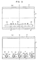
- Figs. 3(a) and 3(b) Shown in Figs. 3(a) and 3(b) is a substance vaporizing apparatus in a first embodiment according to the present invention.
- the substance vaporizing apparatus is provided with a container 22 provided with a plurality of through holes 24.
- the diameters of the through holes 24 nearer to the opposite ends of a discharge tube 2 are greater than those of the through holes 24 nearer to the middle of the discharge tube 2.
- the diameter of the through hole 24 at the middle of the container 22 is on the order of 0.5 mm, and that of the through hole 24 adjacent to the extremity of the container 22 is on the order of 2 mm. Therefore, the metal vapor emitting rate per unit length of the container 22 is lower in the middle portion of the discharge space 3 than in the end portions of the discharge space 3 where the gas temperature Tg gas is lower than that in the middle portion.
- the vapor density is distributed uniformly with respect to the axial direction of the discharge space 3, so that the laser oscillation efficiency per unit length is enhanced.
- the first embodiment has been described on an assumption that the gas temperature Tg in the middle portion of the discharge space 3 is the highest, but a portion where the gas temperature Tg is the highest is not necessarily the middle portion depending on the construction of the substance vaporizing apparatus and the mode of pulse discharge. In such a case, the distribution of the metal vapor emitting rate per unit length may be changed according to the axial distribution of the gas temperature Tg in the discharge tube 2.
- the substance vaporizing apparatus is provided with a plurality of spherical containers 22 respectively having through holes 24 of different diameters.
- the spherical containers 22 are arranged so that the metal vapor is emitted into the end portions of the discharge space 3 at a higher emitting rate per unit length and into the middle portion of the discharge space 3 at a lower emitting rate per unit length. It is also possible to distribute spherical containers 22 provided respectively with through holes 24 of the same diameter so that the density of the through holes 24 increases toward the opposite ends of the discharge space 3.
- Annular containers may be used instead of the spherical containers 22. The annular containers emit the metal vapor into the circumference of the discharge space 3.
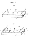
- FIGs. 4(a) and 4(b) are modifications of the container employed in the substance vaporizing apparatus in the first embodiment.
- a container 221 shown in Fig. 4(a) has the shape of a box and is provided with a plurality of through holes 24 differing from each other in diameter. The diameters of the through holes 24 nearer to the opposite ends of the container 221 are greater than those of the through holes 24 nearer to the middle of the container 221.
- a container 221 shown in Fig. 4(b) is provided with a plurality of through holes 24 of the same diameter. The density of the through holes 24 is increased with axial distance from a predetermined axial position in the discharge tube 2.
- These modifications are the same in effect as the container 22 employed in the substance vaporizing apparatus in the second embodiment.
- the first embodiment and its modifications has an effect of increasing the space utilization efficiency, enabling the substance vaporizing apparatus to be formed in a compact construction and enhancing the output of the substance vaporizing apparatus.
- a substance vaporizing apparatus in a second embodiment comprises a gas-filled discharge tube 2 defining a discharge space 3, and a container 222 formed of a porous material, such as a porous ceramic, and provided within the discharge tube 2.
- a vapor generated in the container 222 is emitted from the container 222 through pores into the discharge space 3.
- the metal vapor emitting rate is suppressed by using a porous ceramic material having an appropriate pore density.
- the vapor is emitted in a uniform density distribution into the discharge space 2, so that the laser output is enhanced.
- a laminated porous sheet 223 is formed by laminating a meshed or porous sheet 30, a metal sheet 4 and a substrate 31 in that order, and fastening the sheet 30 and the metal sheet 4 to the substrate 31 with pins 32.
- the laminated porous sheet 223 is wound in a tubular shape with the porous sheet 30 inside so as to surround the discharge space 3.
- the vapor 5 of the metal sheet 4 is emitted through the porous sheet 30 into the discharge space 3.
- the porous sheet 223 has pores formed therein in a small pore density to suppress the vapor emitting rate.
- the substrate 31 may be formed so as to function as a discharge tube 2 as well as the substrate proper.
- the container of the second embodiment has the effect of the second embodiment.
- Fig. 7 shows a substance vaporizing apparatus in a third embodiment according to the present invention.
- the substance vaporizing apparatus comprises a discharge tube 2 defining a discharge space 3, and a plurality of tubular containers 224 and 225 disposed in the periphery of the discharge space 3 and provided with through holes 24.
- Metal vapors 5 generated in the containers 224 and 225 are emitted radially inward through the through holes 24 into the discharge space 3.
- the vapor density in the discharge space is adjusted properly and the vapor is emitted into the discharge space 3 in a uniform vapor density distribution by selectively determining the respective diameters of the through holes 24.
- the containers 224 and 225 may be substituted by the laminated porous sheet employed in the third embodiment.
- the metal vapor is supplied from the periphery of the discharge space 3 so that the metal vapor can uniformly be distributed in the central region of the discharge space 3.
- the vapor emitting rate can be adjusted by selectively determining the respective diameters of the through holes 24, so that the efficiency of utilization can be increased and the substance vaporizing apparatus can be formed in a compact construction.
- Fig. 8 shows a substance vaporizing apparatus in a fourth embodiment according to the present invention.
- This substance vaporizing apparatus comprises a discharge tube 2 defining a discharge space 3, a plurality of containers 224 and 225, and a holding ring 33 for fixedly holding the containers 224 and 225 in the discharge space 3.
- the holding ring 33 is formed of a heat-resistant material, such as a ceramic, molybdenum or tungsten, and is fitted in one end of the discharge tube 2.
- the holding ring 33 is provided with, for example, four holes 33a in which the plurality of containers 224 and 225 are fitted.
- the holding ring 33 fixedly holding the containers 224 and 225 in the end of the discharge tube 2 to disposed the containers 224 and 225 at desired positions within the discharge space 3 so that the efficiency of utilization is increased.
- the substance vaporizing apparatus is able to operate at an improved efficiency.
Landscapes
- Physics & Mathematics (AREA)
- Electromagnetism (AREA)
- Engineering & Computer Science (AREA)
- Plasma & Fusion (AREA)
- Optics & Photonics (AREA)
- Lasers (AREA)
Description
- The present invention relates to a substance vaporizing apparatus for generating a vapor of a substance to be used as an ionizing medium or an exciting medium and, more specifically, to a structure capable of functioning to vaporize a substance.
- A metal vapor laser and a vapor ion laser incorporate such a substance vaporizing apparatus. Fig. 1 shows a conventional metal vapor laser as, for example, published in 6th Nenji Taikai Koen Yoko-shu, 21aIIB3, pp. 60-63 (1986). As shown in Fig. 1, the metal vapor laser comprises discharge electrodes 1a and 1b, a
cylindrical discharge tube 2 defining adischarge space 3 in which ametal vapor 5 produced by vaporizingmetal pieces 4, such as copper pieces, is excited, aheat shield 6 formed of a heat-insulating material, such as wool,resonant mirrors 7a and 7b for laser oscillation,flanges 8a and 8b defining a sealed space including avacuum chamber 9, aninsulating tube 10, asealing tube 11, a gas inlet port 12a, and agas outlet port 12b. - In operation, a pulse voltage is applied across the electrodes 1a and 1b to form a discharge within the
discharge space 3, and then a buffer gas filling thedischarge space 3 is heated by the energy of accelerated ions and electrons to vaporize themetal pieces 4. The ions and electrons accelerated by a pulse discharge and having high energy and high-temperature atoms of the heated buffer gas collide with the atoms of the vaporized metal and transfer their energy, so that the atoms of the vaporized metal is excited to a higher energy level. Theheat shield 6 serves for maintaining the gas at a desired temperature to maintain a predetermined vapor density in thedischarge space 3. The function of thevacuum chamber 9 is similar to that of the heat shield; thevacuum chamber 9 suppresses particularly convection heat loss. Light is emitted when the energy level of the atoms of the vaporized metal drops to a lower energy level or the ground energy level. - The light thus emitted is amplified optically by the
resonant mirrors 7a and 7b to emit a laser beam outside for industrial uses, such as laser machining. - Fig. 2 shows the buffer gas temperature distribution and the vapor density distribution with respect to the diametrical and axial directions of the
discharge space 3 in the metal vapor laser thus constructed. In Fig. 2, X-axis and Y-axis coincide respectively with the diametrical direction and the axial direction of thedischarge space 3; temperature is measured upward on T-axis; indicated at 3a is the center axis of thedischarge space 3 and at 3b are diametrically opposite ends of the discharge space. A curve ℓ represented by a dotted line indicates temperature distribution with respect to the axial direction, curves n₁, n₂ and n₃ represented by alternate long and short dash line indicate vapor distribution with respect to the diametrical direction, and curves m₁, m₂ and m₃ represented by continuous lines indicated temperature distribution with respect to the diametrical direction. As seen in Fig. 2, the temperature of the buffer gas decreases from the central portion of thedischarge space 3 around thecenter axis 3a toward the periphery of thedischarge space 3 represented by the diametricallyopposite ends 3b. The temperature of the buffer gas in the vicinity of the axial ends of thedischarge space 3 is lower than that in the central portion of the same. Since the vapor density distribution within thedischarge tube 2 can be approximated by saturation vapor density n₀, which is a function of buffer gas temperature, the relation between the vapor density distribution curves n₁, n₂ and n₃ is expressed by: n₁ > n₂ = n₃. - On the other hand, when the vapor density increases relative to the buffer gas density (buffer gas pressure), the mean free path of electrons, and the ions and neutral atoms of the buffer gas decreases, and hence the kinetic energy acquired by the electrons and ions from the electric field created by a pulse discharge before colliding against the atoms of the vapor decreases and when the temperature of the atoms of the vapor increase too much, the atoms of the vapor of lower energy level increase, therefore, the population inversion between the number of atoms of the vapor of a higher energy level and that of atoms of the vapor of a lower one is not created, consequently, the electrons and the ions are unable to excite the atoms of the vapor to an energy level high enough to a give a sufficient laser gain. This conventional metal vapor laser has a disadvantage that the vapor density is high in the central portion of the
discharge space 3 and hence the laser power density is low in the central portion of thedischarge space 3. - From DE-A-28 24 761, a substance vaporizing apparatus is known for generating a vapor of a substance for use as an excited medium or an ionized medium in a vapor ion laser, wherein the vapor is generated by heating the substance in a container with holes in a gas-filled discharge tube.
- It is an object of the present invention to provide a substance vaporizing apparatus capable of enhancing the acceleration energy of a laser or an ion beam through the enhancement of laser power by maintaining the density of a vapor of a substance at a value optimum for laser oscillation, which is a relatively low vapor density as compared with the density of a buffer gas filling a discharge space, by suppressing the vaporization of the substance in the discharge space so that the mean free path of the atoms of the vaporized substance is increased thereby increasing the number of atoms of the vaporized substance excited to a higher energy level. The substance vaporizing apparatus according to the invention is defined in
independent claim 1. Preferable embodiments are defined in the dependent claims. - The present invention will become more apparent from the reading of the following description with reference to the accompanying drawings, which, however, are intended only to illustrate the invention and are not to be construed to limit the scope of the present invention.
- Figure 1 is a schematic sectional view of a conventional metal vapor laser;
- Figure 2 is a graph showing the diametrical temperature distribution and the diametrical vapor density distribution in the discharge tube of a conventional substance vaporizing apparatus;
- Figures 3(a) and 3(b) are sectional views of an essential portion of a substance vaporizing apparatus in a first embodiment according to the present invention;
- Figure 4(a) and 4(b) are perspective views respectively showing modifications of the substance vaporizing apparatus in the first embodiment according to the present invention;
- Figure 5 is a sectional view of an essential portion of a substance vaporizing apparatus in a second embodiment according to the present invention;
- Figure 6 is a perspective view of a porous member employed in the substance vaporizing apparatus in the second embodiment according to the present invention;
- Figure 7 is a sectional view of an essential portion of a substance vaporizing apparatus in a third embodiment according to the present invention;
- Figure 8 is a sectional view of an essential portion of a substance vaporizing apparatus in a fourth embodiment according to the present invention; and
- Figure 9 is a perspective view of a ring employed in the substance vaporizing apparatus in the fourth embodiment according to the present invention;
- Shown in Figs. 3(a) and 3(b) is a substance vaporizing apparatus in a first embodiment according to the present invention.
- In a construction shown in Fig. 3(a), the substance vaporizing apparatus is provided with a
container 22 provided with a plurality of throughholes 24. The diameters of the throughholes 24 nearer to the opposite ends of adischarge tube 2 are greater than those of the throughholes 24 nearer to the middle of thedischarge tube 2. For example, the diameter of thethrough hole 24 at the middle of thecontainer 22 is on the order of 0.5 mm, and that of the throughhole 24 adjacent to the extremity of thecontainer 22 is on the order of 2 mm. Therefore, the metal vapor emitting rate per unit length of thecontainer 22 is lower in the middle portion of thedischarge space 3 than in the end portions of thedischarge space 3 where the gas temperature Tg gas is lower than that in the middle portion. Thus, the vapor density is distributed uniformly with respect to the axial direction of thedischarge space 3, so that the laser oscillation efficiency per unit length is enhanced. The first embodiment has been described on an assumption that the gas temperature Tg in the middle portion of thedischarge space 3 is the highest, but a portion where the gas temperature Tg is the highest is not necessarily the middle portion depending on the construction of the substance vaporizing apparatus and the mode of pulse discharge. In such a case, the distribution of the metal vapor emitting rate per unit length may be changed according to the axial distribution of the gas temperature Tg in thedischarge tube 2. - In a construction shown in Fig. 3(b), the substance vaporizing apparatus is provided with a plurality of
spherical containers 22 respectively having throughholes 24 of different diameters. Thespherical containers 22 are arranged so that the metal vapor is emitted into the end portions of thedischarge space 3 at a higher emitting rate per unit length and into the middle portion of thedischarge space 3 at a lower emitting rate per unit length. It is also possible to distributespherical containers 22 provided respectively with throughholes 24 of the same diameter so that the density of the throughholes 24 increases toward the opposite ends of thedischarge space 3. Annular containers may be used instead of thespherical containers 22. The annular containers emit the metal vapor into the circumference of thedischarge space 3. - Shown in Figs. 4(a) and 4(b) are modifications of the container employed in the substance vaporizing apparatus in the first embodiment. A
container 221 shown in Fig. 4(a) has the shape of a box and is provided with a plurality of throughholes 24 differing from each other in diameter. The diameters of the throughholes 24 nearer to the opposite ends of thecontainer 221 are greater than those of the throughholes 24 nearer to the middle of thecontainer 221. Acontainer 221 shown in Fig. 4(b) is provided with a plurality of throughholes 24 of the same diameter. The density of thethrough holes 24 is increased with axial distance from a predetermined axial position in thedischarge tube 2. These modifications are the same in effect as thecontainer 22 employed in the substance vaporizing apparatus in the second embodiment. The first embodiment and its modifications has an effect of increasing the space utilization efficiency, enabling the substance vaporizing apparatus to be formed in a compact construction and enhancing the output of the substance vaporizing apparatus. - Referring to Figs. 5 and 6, a substance vaporizing apparatus in a second embodiment according to the present invention comprises a gas-filled
discharge tube 2 defining adischarge space 3, and acontainer 222 formed of a porous material, such as a porous ceramic, and provided within thedischarge tube 2. A vapor generated in thecontainer 222 is emitted from thecontainer 222 through pores into thedischarge space 3. The metal vapor emitting rate is suppressed by using a porous ceramic material having an appropriate pore density. Thus, the vapor is emitted in a uniform density distribution into thedischarge space 2, so that the laser output is enhanced. - Referring to Fig. 6, a laminated
porous sheet 223 is formed by laminating a meshed orporous sheet 30, ametal sheet 4 and asubstrate 31 in that order, and fastening thesheet 30 and themetal sheet 4 to thesubstrate 31 withpins 32. The laminatedporous sheet 223 is wound in a tubular shape with theporous sheet 30 inside so as to surround thedischarge space 3. Thevapor 5 of themetal sheet 4 is emitted through theporous sheet 30 into thedischarge space 3. Theporous sheet 223 has pores formed therein in a small pore density to suppress the vapor emitting rate. Thesubstrate 31 may be formed so as to function as adischarge tube 2 as well as the substrate proper. The container of the second embodiment has the effect of the second embodiment. - Fig. 7 shows a substance vaporizing apparatus in a third embodiment according to the present invention. As shown in Fig. 7, the substance vaporizing apparatus comprises a
discharge tube 2 defining adischarge space 3, and a plurality oftubular containers discharge space 3 and provided with throughholes 24.Metal vapors 5 generated in thecontainers holes 24 into thedischarge space 3. The vapor density in the discharge space is adjusted properly and the vapor is emitted into thedischarge space 3 in a uniform vapor density distribution by selectively determining the respective diameters of the through holes 24. Thecontainers discharge space 3 so that the metal vapor can uniformly be distributed in the central region of thedischarge space 3. The vapor emitting rate can be adjusted by selectively determining the respective diameters of the throughholes 24, so that the efficiency of utilization can be increased and the substance vaporizing apparatus can be formed in a compact construction. - Fig. 8 shows a substance vaporizing apparatus in a fourth embodiment according to the present invention. This substance vaporizing apparatus comprises a
discharge tube 2 defining adischarge space 3, a plurality ofcontainers ring 33 for fixedly holding thecontainers discharge space 3. As shown in Fig. 8, the holdingring 33 is formed of a heat-resistant material, such as a ceramic, molybdenum or tungsten, and is fitted in one end of thedischarge tube 2. As shown in Fig. 9, the holdingring 33 is provided with, for example, fourholes 33a in which the plurality ofcontainers ring 33 fixedly holding thecontainers discharge tube 2 to disposed thecontainers discharge space 3 so that the efficiency of utilization is increased. Thus, the substance vaporizing apparatus is able to operate at an improved efficiency.
Claims (4)
- A substance vaporizing apparatus for generating a vapor of a substance for use as an excited medium or an ionized medium in a vapor ion laser and wherein the vapor (5) is generated by heating the substance (4) in a gas-filled tube (2) defining a discharge space (3) and having discharge electrodes (1a, 1b), comprising at least one container (22) containing the substance (4), said at least one container (22) being disposed within the gas-filled tube (2) and in the case of said apparatus comprising only one container (22), said one container being provided with a plurality of holes (24) extending through its wall and in the case of said apparatus comprising a plurality of containers (22), each container being provided with one or a plurality of holes (24) extending through its wall; whereby said holes serve to connect the interior of said at least one container (22) with the interior of said gas-filled tube (2), thereby forming a flow passage for vapor (5) generated within said at least one container (22) to flow from the interior of said at least one container (22) into the interior of said gas-filled tube (2); whereina) the respective diameters of said holes (24) nearer to the axially opposite ends of the tube (2) are greater than the diameters of said holes (24) nearer to the middle of the tube (2) orb) the distances between said holes (24) nearer to the axially opposite ends of the tube (2) are smaller than the distances between said holes (24) nearer to the middle of the tube (2),whereby the combined area of said holes (24) per unit length of said tube (2) is greater nearer to the axially opposite ends of the tube (2) than nearer to the middle of the tube (2) and the vapor (5) emitting rate of the container (22) is thereby varied with respect to the axial direction of the gas-filled tube (2) so that a substantially uniformly distributed vapor density is established in the axial direction within the tube (2).
- A substance vaporizing apparatus according to claim 1 comprising only one container (22), wherein the container (22) is a porous member positioned to extend around said substance (4) whereby the pores of said porous member constitute said holes, said porous member being positioned within the gas-filled tube (2) and providing a porous flow path for the vapor (5) generated within said porous member to flow from the interior of said porous member into the interior of said gas-filled tube (2).
- A substance vaporizing apparatus according to claim 1, comprising a plurality of said containers (22) containing the substance (4), said containers (22) being arranged around said discharge space (3), each of said containers (22) being provided with a plurality of holes (24) extending through its wall to connect the interior of each of said containers (22) with said discharge space (3), thereby forming a flow passage for the vapor (5) generated within each of said containers (22) to flow from the interior of each of said containers (22) into said discharge space (3) of said gas-filled tube (2).
- A substance vaporizing apparatus according to claim 1 or claim 3, comprising:
one or a plurality of containers (224, 225) containing the substance (4) disposed within the gas-filled tube (2); and a holding member (33) fixedly holding the container or containers (224, 225) in a fixed position within the gas-filled tube (2).
Priority Applications (1)
| Application Number | Priority Date | Filing Date | Title |
|---|---|---|---|
| EP94111354A EP0622875B1 (en) | 1989-06-14 | 1990-06-12 | Substance vaporizing apparatus |
Applications Claiming Priority (6)
| Application Number | Priority Date | Filing Date | Title |
|---|---|---|---|
| JP15192789A JPH0317260A (en) | 1989-06-14 | 1989-06-14 | Material vapor generator |
| JP151933/89 | 1989-06-14 | ||
| JP15193389A JPH0318076A (en) | 1989-06-14 | 1989-06-14 | Metal vapor laser device |
| JP152675/89 | 1989-06-14 | ||
| JP1152675A JP2760059B2 (en) | 1989-06-14 | 1989-06-14 | Material vapor generator |
| JP151927/89 | 1989-06-14 |
Related Child Applications (2)
| Application Number | Title | Priority Date | Filing Date |
|---|---|---|---|
| EP94111354A Division EP0622875B1 (en) | 1989-06-14 | 1990-06-12 | Substance vaporizing apparatus |
| EP94111354.0 Division-Into | 1994-07-21 |
Publications (3)
| Publication Number | Publication Date |
|---|---|
| EP0402842A2 EP0402842A2 (en) | 1990-12-19 |
| EP0402842A3 EP0402842A3 (en) | 1992-02-26 |
| EP0402842B1 true EP0402842B1 (en) | 1995-09-20 |
Family
ID=27320189
Family Applications (2)
| Application Number | Title | Priority Date | Filing Date |
|---|---|---|---|
| EP94111354A Expired - Lifetime EP0622875B1 (en) | 1989-06-14 | 1990-06-12 | Substance vaporizing apparatus |
| EP90111049A Expired - Lifetime EP0402842B1 (en) | 1989-06-14 | 1990-06-12 | Substance vaporizing apparatus |
Family Applications Before (1)
| Application Number | Title | Priority Date | Filing Date |
|---|---|---|---|
| EP94111354A Expired - Lifetime EP0622875B1 (en) | 1989-06-14 | 1990-06-12 | Substance vaporizing apparatus |
Country Status (3)
| Country | Link |
|---|---|
| US (1) | US5150375A (en) |
| EP (2) | EP0622875B1 (en) |
| DE (2) | DE69031430T2 (en) |
Cited By (1)
| Publication number | Priority date | Publication date | Assignee | Title |
|---|---|---|---|---|
| DE102010055285A1 (en) | 2010-12-21 | 2012-06-21 | Solarion Ag Photovoltaik | Evaporator source, evaporator chamber and coating process |
Families Citing this family (9)
| Publication number | Priority date | Publication date | Assignee | Title |
|---|---|---|---|---|
| GB2262184B (en) * | 1991-11-07 | 1995-06-07 | Mitsubishi Electric Corp | Pulse laser apparatus |
| JPH0613196A (en) * | 1992-06-25 | 1994-01-21 | Matsushita Electric Ind Co Ltd | Plasma generation method and generator |
| US5327446A (en) * | 1993-03-26 | 1994-07-05 | The United States Of America As Represented By The Secretary Of The Department Of Health And Human Services | Method of exciting laser action and delivering laser energy for medical and scientific applications |
| US6738400B1 (en) * | 1993-07-07 | 2004-05-18 | The United States Of America As Represented By The United States Department Of Energy | Large diameter lasing tube cooling arrangement |
| DE4422697C1 (en) * | 1994-06-29 | 1996-01-25 | Zsw | Vapour coating device for prodn. of thin filmed solar cells |
| FR2743204B1 (en) * | 1996-01-03 | 1998-02-13 | Commissariat Energie Atomique | METAL VAPOR LASER DEVICE |
| FR2836772B1 (en) * | 2002-03-04 | 2004-07-09 | Absys | GAS GENERATOR FOR A STERILIZATION SYSTEM |
| US20030168013A1 (en) * | 2002-03-08 | 2003-09-11 | Eastman Kodak Company | Elongated thermal physical vapor deposition source with plural apertures for making an organic light-emitting device |
| RU2618477C1 (en) * | 2015-12-24 | 2017-05-03 | Федеральное государственное автономное образовательное учреждение высшего образования "Национальный исследовательский Томский государственный университет" (ТГУ, НИ ТГУ) | Impulse-periodic laser on pairs of chemical elements |
Family Cites Families (12)
| Publication number | Priority date | Publication date | Assignee | Title |
|---|---|---|---|---|
| FR2092912B1 (en) * | 1970-06-30 | 1973-12-21 | Comp Generale Electricite | |
| US4021845A (en) * | 1975-10-16 | 1977-05-03 | Xerox Corporation | Laser for generating white light |
| US4052680A (en) * | 1976-07-01 | 1977-10-04 | Xerox Corporation | Metal vapor laser having cataphoresis means |
| DE2824761A1 (en) * | 1977-06-08 | 1978-12-14 | Gen Electric | DISCHARGE HEATED COPPER VAPOR LASER |
| US4639926A (en) * | 1980-06-09 | 1987-01-27 | Xerox Corporation | Efficient cathode assembly for metal vapor laser |
| JPS5835992A (en) * | 1981-08-28 | 1983-03-02 | Mita Ind Co Ltd | Laser tube utilizing negative glow |
| JPS61244081A (en) * | 1985-04-23 | 1986-10-30 | Koito Mfg Co Ltd | Metal ion laser |
| JPH06101605B2 (en) * | 1985-07-22 | 1994-12-12 | 株式会社小糸製作所 | Metal ion laser |
| US4677636A (en) * | 1985-10-23 | 1987-06-30 | The United States Of America As Represented By The Administrator Of The National Aeronautics And Space Administration | Multiplex electric discharge gas laser system |
| GB8711212D0 (en) * | 1987-05-12 | 1987-06-17 | English Electric Valve Co Ltd | Laser apparatus |
| JPS63281484A (en) * | 1987-05-13 | 1988-11-17 | Ushio Inc | Hollow cathode metal vapor laser tube |
| US4975924A (en) * | 1987-08-13 | 1990-12-04 | Mitsubishi Denki Kabushiki Kaisha | Metallic vapor laser apparatus |
-
1990
- 1990-06-11 US US07/535,615 patent/US5150375A/en not_active Expired - Fee Related
- 1990-06-12 EP EP94111354A patent/EP0622875B1/en not_active Expired - Lifetime
- 1990-06-12 EP EP90111049A patent/EP0402842B1/en not_active Expired - Lifetime
- 1990-06-12 DE DE69031430T patent/DE69031430T2/en not_active Expired - Fee Related
- 1990-06-12 DE DE69022487T patent/DE69022487T2/en not_active Expired - Fee Related
Cited By (2)
| Publication number | Priority date | Publication date | Assignee | Title |
|---|---|---|---|---|
| DE102010055285A1 (en) | 2010-12-21 | 2012-06-21 | Solarion Ag Photovoltaik | Evaporator source, evaporator chamber and coating process |
| WO2012084165A1 (en) | 2010-12-21 | 2012-06-28 | Solarion Ag - Photovoltaik | Vaporization source, vaporization chamber, coating method and nozzle plate |
Also Published As
| Publication number | Publication date |
|---|---|
| DE69031430D1 (en) | 1997-10-16 |
| EP0402842A2 (en) | 1990-12-19 |
| US5150375A (en) | 1992-09-22 |
| DE69022487T2 (en) | 1996-02-08 |
| EP0622875A1 (en) | 1994-11-02 |
| EP0402842A3 (en) | 1992-02-26 |
| EP0622875B1 (en) | 1997-09-10 |
| DE69022487D1 (en) | 1995-10-26 |
| DE69031430T2 (en) | 1998-01-22 |
Similar Documents
| Publication | Publication Date | Title |
|---|---|---|
| US2755014A (en) | Ionic vacuum pump device | |
| US4942588A (en) | Laser device | |
| KR100586050B1 (en) | Improved device for charged particle beam | |
| JPH0337277B2 (en) | ||
| GB2079523A (en) | Metal vapour laser | |
| JP3738181B2 (en) | Plasma injector | |
| EP0095311B1 (en) | Ion source apparatus | |
| US5150375A (en) | Substance vaporizing apparatus | |
| JP2595188B2 (en) | Compact high-current crossed-field plasma switch | |
| EP0204060B1 (en) | A compact low-pressure mercury vapour discharge lamp | |
| US4991180A (en) | Metallic vapor laser apparatus | |
| JPS6355987A (en) | Laser device | |
| US4825446A (en) | Laser apparatus having cathode bore directing electron beam onto anode | |
| US4041415A (en) | Coaxial electron beam pumped laser | |
| JP2760059B2 (en) | Material vapor generator | |
| US3250947A (en) | Discharge device having electron grids with heights rising substantially above the grid support rims | |
| US3750047A (en) | Gas laser having excitation chambers with multiple channels | |
| US3338506A (en) | Vacuum pump apparatus | |
| JPS63199470A (en) | Metallic vapor laser oscillating tube | |
| JPH0635487Y2 (en) | Metal vapor laser discharge tube | |
| JPH07307505A (en) | Gas laser device | |
| JPH0317256A (en) | Material vapor generator | |
| JP4436003B2 (en) | Vacuum deposition system | |
| JPH0554812A (en) | Ion source | |
| JPS6139593A (en) | Metallic vapor laser |
Legal Events
| Date | Code | Title | Description |
|---|---|---|---|
| PUAI | Public reference made under article 153(3) epc to a published international application that has entered the european phase |
Free format text: ORIGINAL CODE: 0009012 |
|
| AK | Designated contracting states |
Kind code of ref document: A2 Designated state(s): DE FR GB |
|
| PUAL | Search report despatched |
Free format text: ORIGINAL CODE: 0009013 |
|
| AK | Designated contracting states |
Kind code of ref document: A3 Designated state(s): DE FR GB |
|
| RHK1 | Main classification (correction) |
Ipc: H01S 3/227 |
|
| 17P | Request for examination filed |
Effective date: 19920819 |
|
| 17Q | First examination report despatched |
Effective date: 19931025 |
|
| GRAA | (expected) grant |
Free format text: ORIGINAL CODE: 0009210 |
|
| AK | Designated contracting states |
Kind code of ref document: B1 Designated state(s): DE FR GB |
|
| XX | Miscellaneous (additional remarks) |
Free format text: TEILANMELDUNG 94111354.0 EINGEREICHT AM 12/06/90. |
|
| REF | Corresponds to: |
Ref document number: 69022487 Country of ref document: DE Date of ref document: 19951026 |
|
| ET | Fr: translation filed | ||
| PLBE | No opposition filed within time limit |
Free format text: ORIGINAL CODE: 0009261 |
|
| STAA | Information on the status of an ep patent application or granted ep patent |
Free format text: STATUS: NO OPPOSITION FILED WITHIN TIME LIMIT |
|
| 26N | No opposition filed | ||
| PGFP | Annual fee paid to national office [announced via postgrant information from national office to epo] |
Ref country code: GB Payment date: 20000607 Year of fee payment: 11 |
|
| PGFP | Annual fee paid to national office [announced via postgrant information from national office to epo] |
Ref country code: FR Payment date: 20000612 Year of fee payment: 11 |
|
| PGFP | Annual fee paid to national office [announced via postgrant information from national office to epo] |
Ref country code: DE Payment date: 20000614 Year of fee payment: 11 |
|
| REG | Reference to a national code |
Ref country code: FR Ref legal event code: D6 |
|
| PG25 | Lapsed in a contracting state [announced via postgrant information from national office to epo] |
Ref country code: GB Free format text: LAPSE BECAUSE OF NON-PAYMENT OF DUE FEES Effective date: 20010612 |
|
| GBPC | Gb: european patent ceased through non-payment of renewal fee |
Effective date: 20010612 |
|
| PG25 | Lapsed in a contracting state [announced via postgrant information from national office to epo] |
Ref country code: FR Free format text: LAPSE BECAUSE OF NON-PAYMENT OF DUE FEES Effective date: 20020228 |
|
| PG25 | Lapsed in a contracting state [announced via postgrant information from national office to epo] |
Ref country code: DE Free format text: LAPSE BECAUSE OF NON-PAYMENT OF DUE FEES Effective date: 20020403 |