EP0402829A2 - Method and device for detecting an intruder using a passive infra-red motion detector - Google Patents
Method and device for detecting an intruder using a passive infra-red motion detector Download PDFInfo
- Publication number
- EP0402829A2 EP0402829A2 EP90111007A EP90111007A EP0402829A2 EP 0402829 A2 EP0402829 A2 EP 0402829A2 EP 90111007 A EP90111007 A EP 90111007A EP 90111007 A EP90111007 A EP 90111007A EP 0402829 A2 EP0402829 A2 EP 0402829A2
- Authority
- EP
- European Patent Office
- Prior art keywords
- heat source
- sensor
- intruder
- signals
- sensor elements
- Prior art date
- Legal status (The legal status is an assumption and is not a legal conclusion. Google has not performed a legal analysis and makes no representation as to the accuracy of the status listed.)
- Withdrawn
Links
Images


Classifications
-
- G—PHYSICS
- G08—SIGNALLING
- G08B—SIGNALLING SYSTEMS, e.g. PERSONAL CALLING SYSTEMS; ORDER TELEGRAPHS; ALARM SYSTEMS
- G08B13/00—Burglar, theft or intruder alarms
- G08B13/18—Actuation by interference with heat, light, or radiation of shorter wavelength; Actuation by intruding sources of heat, light, or radiation of shorter wavelength
- G08B13/189—Actuation by interference with heat, light, or radiation of shorter wavelength; Actuation by intruding sources of heat, light, or radiation of shorter wavelength using passive radiation detection systems
- G08B13/19—Actuation by interference with heat, light, or radiation of shorter wavelength; Actuation by intruding sources of heat, light, or radiation of shorter wavelength using passive radiation detection systems using infrared-radiation detection systems
- G08B13/193—Actuation by interference with heat, light, or radiation of shorter wavelength; Actuation by intruding sources of heat, light, or radiation of shorter wavelength using passive radiation detection systems using infrared-radiation detection systems using focusing means
-
- G—PHYSICS
- G08—SIGNALLING
- G08B—SIGNALLING SYSTEMS, e.g. PERSONAL CALLING SYSTEMS; ORDER TELEGRAPHS; ALARM SYSTEMS
- G08B13/00—Burglar, theft or intruder alarms
- G08B13/18—Actuation by interference with heat, light, or radiation of shorter wavelength; Actuation by intruding sources of heat, light, or radiation of shorter wavelength
- G08B13/189—Actuation by interference with heat, light, or radiation of shorter wavelength; Actuation by intruding sources of heat, light, or radiation of shorter wavelength using passive radiation detection systems
- G08B13/19—Actuation by interference with heat, light, or radiation of shorter wavelength; Actuation by intruding sources of heat, light, or radiation of shorter wavelength using passive radiation detection systems using infrared-radiation detection systems
Definitions
- the invention relates to a method for detecting an intruder, which is a moving heat source, by means of a passive infrared motion detector with a sensor head which has a plurality of sensor elements, each of which detects a lobe-shaped area and emits a signal when the heat source enters, and an apparatus for performing this method.
- Passive infrared motion detectors or sensors are known per se; they generally have facet mirrors or facet lenses so that they can be used as motion detectors.
- the facet optic creates several narrow zones in the field of view of the sensor and maps them to a differential element that is sensitive to infrared radiation. If a heat source crosses one of the zones, a typical signal pattern results, with positive and negative signal pulses which are used for evaluation.
- these known infrared sensors which have a very different design, have certain disadvantages.
- the evaluation strategies for avoiding false alarms are usually based on the selection of certain signal patterns for triggering the alarm.
- EP-A-0 107 042 In order to reduce false alarms, it has already been proposed in EP-A-0 107 042 to provide two sensor elements.
- the current signal obtained from a first sensor element is continuously compared in a correlator with reference signals which are stored in a read-only memory and with the current signals obtained from a second sensor element monitoring the close range.
- the correlator emits an output signal which corresponds to the correlation of the two signals compared with one another.
- An alarm signal is triggered when the correlation exceeds a predetermined value and the amplitude reaches the threshold.
- the second sensor is here used for reference only. Spatial imaging is not possible with the known infrared detector. It is also not possible to determine the typical course of a measured value curve caused by an intruder.
- the object of the invention is to avoid the disadvantages mentioned above and to provide a method and a device which ensures precise spatial monitoring of the area to be protected and permits reliable alarming, false alarms and tampering being largely excluded.
- the area to be protected is monitored by two angle-selective passive infrared sensor heads with different locations.
- two pyrodectors can be used as angle-sensitive sensor heads, as are known from EP-A-0 245 842.
- a PVDF film with a row of sensor elements is attached in the focal plane of a spherical or spherical-parabolic mirror. This mirror optic assigns a corresponding lobe in the detection range to each individual sensor element, so that angle-selective detection of an infrared radiation source is possible.
- Such a heat source is aimed from two different directions and its location can be continuously determined by triangulation.
- the movement path of the heat source and thus the track of the intruder can be recorded in the common detection area of both sensor heads and a reliable alarm criterion for a movement detector can be derived from this movement path or track.
- false alarms such as can be caused, for example, by radiators switching on, air movement or solar radiation, are virtually excluded. Due to the spatial resolution is advantageously clearly recognized whether the intruder has actually traveled a certain distance in the surveillance area.
- a radial movement ie a movement directly towards one of the sensor heads, is also clearly identified, such as a small animal which cannot be detected and which is in the immediate vicinity of a sensor, is recognized as a non-intruder and does not give rise to an alarm.
- signals of different heights are generated in the individual sensor elements, which are separately amplified and digitized for each sensor element.
- the signals obtained in this way are expediently processed further in a microprocessor, a direction vector to the heat source being calculated for each sensor head by geometrically correct weighting of the individual digitized signals. From the intersection of two corresponding direction vectors, the current position of the heat source is continuously determined and from this the track that the intruder travels is formed. In this case, an alarm criterion is advantageously derived from the shape and length of the track and an alarm signal is emitted.
- the direction of movement or position of the intruder can also be displayed as additional information.
- a conventional facet detector is shown as a drawing in plan view.
- Such a detector is e.g. known from DE-OS 2 103 909.
- a new type of infrared sensor is shown schematically, which is designed as an angle-selective passive sensor head SK, an optical arrangement being used in which an array of electrically and thermally separated sensor elements SE lies in the focal plane of a spherical mirror KS, as it is is known from the above-mentioned European patent application 0 245 842.
- Each sensor element SE is assigned a club-shaped detection area KB by the mirror optics (KS).
- the geometry of the individual beam lobes KB is determined by the focal length of the spherical mirror KS and the number, shape and size of the selective zones.
- a sensor head SK1 has at least four sensor elements (SE) which form four lobe-shaped monitoring areas KB.
- a heat source in the present case an intruder EN
- enters the detection area EB of the sensor heads SK1 and SK2 signals of different heights occur in the individual sensor elements SE depending on the position and extent of the heat source.
- a direction vector RV1, RV2 to the heat source EN is calculated with a computer by geometrically correct weighting of the individual signals for each sensor head SK1, SK2.
- the current position of the heat source EN results from the intersection of the two direction detectors RV1, RV2. By continuously calculating this position, the trace of the object is traced in the computer and the alarm trigger is derived from it. In addition, the.
- the display device Trajectory or the position of the intruder can be graphed or otherwise displayed.
- Each sensor head SK1 and SK2 here has, for example, four sensor elements SE, the signals of which are each fed to an analog-digital converter AD via an amplifier VER.
- the digitized signals of both sensor heads SK1, SK2 and all sensor elements SE are fed to a microcomputer ⁇ R, which carries out the corresponding processing of these signals.
- the microcomputer ⁇ R has a control panel BF and a display device ANZ, via which an alarm signal is displayed, which can be output optically or acoustically as alarm AL.
- the movement path or position of the intruder can also be displayed on a colored screen BS connected to the display device ANZ.
- the invention not only has the advantage that fixed temperature changes do not lead to a false alarm, it also has the advantage that false alarms are reduced by better delimitation of the monitoring area. Small animals in the close range of the sensor cannot trigger false alarms either, because the distance information enables a better estimate of the intensity of the heat source and can thus be recognized whether it is an actual intruder or a fly.
Landscapes
- Physics & Mathematics (AREA)
- General Physics & Mathematics (AREA)
- Burglar Alarm Systems (AREA)
Abstract
Ein Sensorkopf (SK) weist mehrere Sensorelemente auf, welche jeweils einen keulenförmigen Bereich (KB) erfassen und bei Eintritt der Wärmequelle (EN) ein Signal abgeben. Es sind zumindest zwei Infrarot-Sensorköpfe (SK1, SK2) in einem bestimmten Abstand (a) zueinander angeordnet und auf einen gemeinsamen Erfassungsbereich (EB) ausgerichtet. Aus den abgegebenen Signalen wird durch Triangulation die Bewegungsbahn der Wärmequelle (EN) ermittelt und hieraus ein Alarmkriterium abgeleitet. Dabei werden die in Abhängigkeit von der Position und der Ausdehnung der Wärmequelle (EN) unterschiedlich hohen, in den einzelnen Sensorelementen auftretenden Signale jeweils verstärkt und digitalisiert. Durch geometrisch richtige Richtung der einzelnen digitalisierten Signale wird für jeden Sensorkopf (SK1, SK2) ein Richtungsvektor zur Wärmequelle (EN) berechnet und fortlaufend aus den Schnittpunkten zweier entsprechender Richtungsvektoren die momentane Position der Wärmequelle ermittelt. Hieraus wird die Spur der sich bewegenden Wärmequelle gebildet und aus der Form und Länge der Spur ein Alarmkriterium abgeleitet.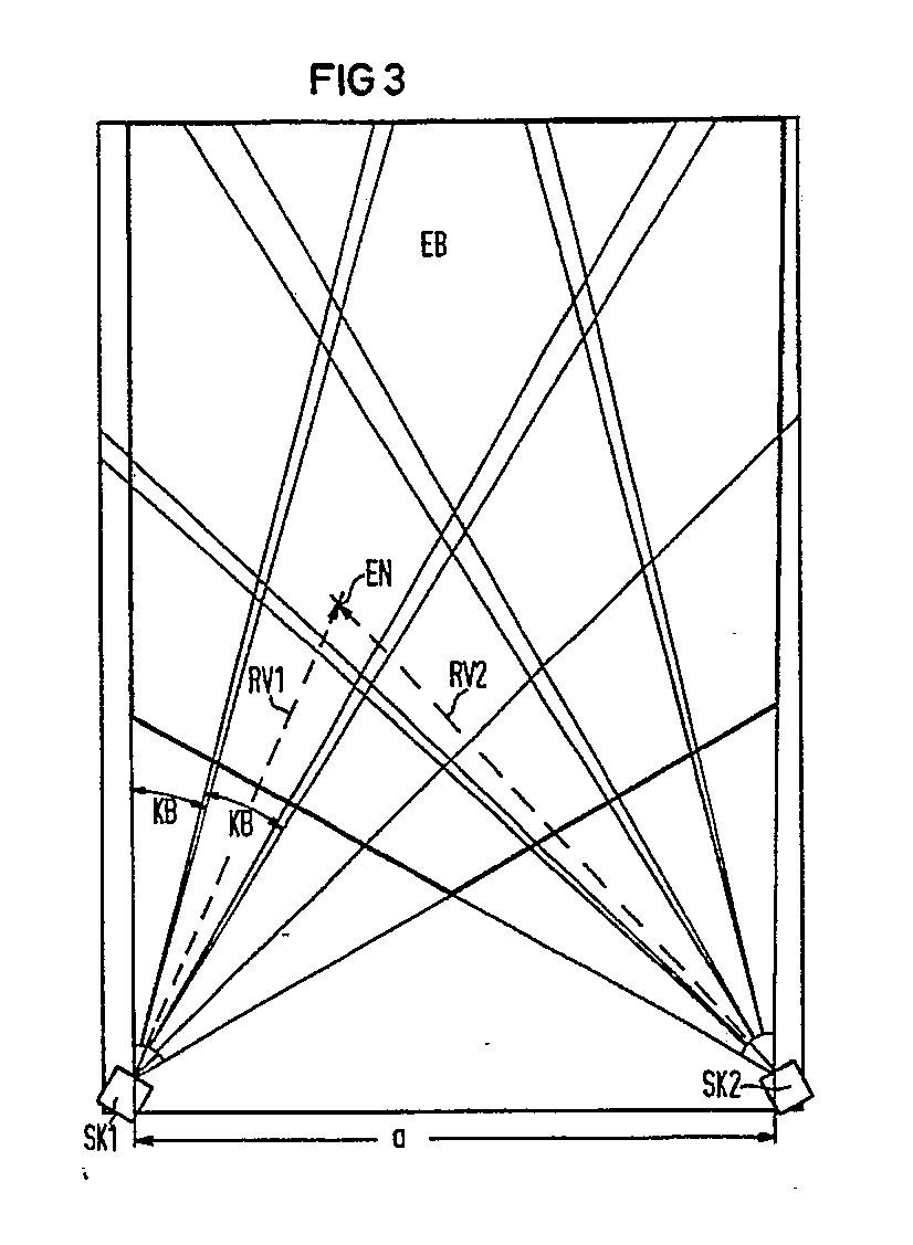
Description
Die Erfindung bezieht sich auf ein Verfahren zum Detektieren eines Eindringlings, der eine sich bewegende Wärmequelle darstellt, mittels eines passiven Infrarot-Bewegungsmelders mit einem Sensorkopf, der mehrere Sensorelemente aufweist, welche jeweils einen keulenförmigen Bereich erfassen und bei Eintritt der Wärmequelle ein Signal abgeben, und eine Vorrichtung zur Durchführung dieses Verfahrens.The invention relates to a method for detecting an intruder, which is a moving heat source, by means of a passive infrared motion detector with a sensor head which has a plurality of sensor elements, each of which detects a lobe-shaped area and emits a signal when the heat source enters, and an apparatus for performing this method.
Zum Schutz von Räumen gegen unerlaubtes Eindringen von Personen wird die Tatsache genutzt, daß der Mensch als Wärmequelle eine höhere Temperatur als seine Umgebung aufweist. Die dadurch bedingte erhöhte Abstrahlung von langwelligen Infrarotstrahlen wird durch an sich bekannte Passiv-Infrarot-Detektoren erfaßt. Bei derartigen Überwachungsvorrichtungen tritt häufig das Problem auf, daß beim Einschalten von Heizungen und Klimaanlagen oder bei plötzlicher Sonneneinstrahlung oder Luftbewegung ebenfalls Temperaturänderungen im Gesichtsfeld des Infrarot-Detektors erzeugt werden. Bei der Erfassung von Eindringlingen mittels passiven Infrarot-Bewegungsmeldern besteht grundsätzlich das Problem, solche ortsfesten Temperaturänderungen mit großer Sicherheit von einer sich bewegenden Wärmequelle unterscheiden zu können, wie sie eine in den Erfassungsbereich eindringende Person darstellt.To protect rooms against unauthorized intrusion of people, the fact is used that the human being as a heat source is at a higher temperature than its surroundings. The resulting increased radiation of long-wave infrared rays is detected by known passive infrared detectors. Such monitoring devices frequently have the problem that when heating and air conditioning systems are switched on or when there is sudden exposure to sunlight or air movement, temperature changes are also generated in the field of view of the infrared detector. When capturing intruders using passive infrared motion detectors, there is basically the problem of being able to distinguish with certainty such fixed temperature changes from a moving heat source as is represented by a person entering the detection area.
Passive Infrarot-Bewegungsmelder bzw. -sensoren sind an sich bekannt; sie weisen im allgemeinen Facettenspiegel oder Facettenlinsen auf, um als Bewegungsmelder eingesetzt werden zu können. Die Facetten-Optik erzeugt im Gesichtsfeld des Sensors mehrere enge Zonen und bildet diese auf ein für Infrarot-Strahlung empfindliches Differenz-Element ab.
Durchquert eine Wärmequelle eine der Zonen, so ergibt sich ein typisches Signalmuster, mit positiven und negativen Signalpul sen, welche zur Auswertung herangezogen werden. Dennoch haben diese bekannten, im Aufbau sehr unterschiedlich gestalteten Infrarot-Sensoren gewisse Nachteile. Die Auswertestrategien zur Vermeidung von Falschalarmen beruhen in der Regel auf der Auswahl von bestimmten Signalmustern zur Alarmauslösung. Dabei ist es jedoch nicht möglich, eine Aussage über den zurückgelegten Weg der Wärmequelle zu machen, da entsprechende Signalmuster auch erzeugt werden, wenn die Wärmequelle nur in ihrer Temperatur schwankt oder auch nur geringfügige Pendelbewegungen macht. Dies kommt daher, weil die gesamte Wärmebild-Information des Raumes bei diesem Verfahren auf ein einziges Signal reduziert wird, welches keinen eindeutigen Rückschluß auf die Situation im Überwachungsbereich mehr zuläßt. Begrenzt man daher zur Vermeidung von Falschalarmen die Alarmauslösung auf eine kleine Klasse von eng definierten Signalmustern, so ergeben sich daraus für einen intelligenten Eindringling erfolgreiche Überwindungsstrategien.Passive infrared motion detectors or sensors are known per se; they generally have facet mirrors or facet lenses so that they can be used as motion detectors. The facet optic creates several narrow zones in the field of view of the sensor and maps them to a differential element that is sensitive to infrared radiation.
If a heat source crosses one of the zones, a typical signal pattern results, with positive and negative signal pulses which are used for evaluation. Nevertheless, these known infrared sensors, which have a very different design, have certain disadvantages. The evaluation strategies for avoiding false alarms are usually based on the selection of certain signal patterns for triggering the alarm. However, it is not possible to make a statement about the distance covered by the heat source, since corresponding signal patterns are also generated when the heat source only fluctuates in temperature or makes only slight pendulum movements. This is because the entire thermal image information of the room is reduced to a single signal with this method, which no longer allows a clear conclusion to be drawn about the situation in the monitored area. Therefore, if you limit the alarm triggering to a small class of narrowly defined signal patterns to avoid false alarms, this results in successful overcoming strategies for an intelligent intruder.
Diese Mehrdeutigkeit eines solches Verfahrens zeigt sich auch darin, daß nicht unterschieden werden kann, ob ein Objekt wärmer oder kälter als die Umgebung ist, oder ob es von links nach rechts oder von rechts nach links den Erfassungsbereich durchquert. Ferner können durch eine übergroße Empfindlichkeit im Nahbereich des Sensors Kleintiere zu Falschalarmen führen. Ebensowenig ist der Sensor verhältnismäßig unempfindlich bei radialen Bewegungen.This ambiguity of such a method is also evident in the fact that it cannot be distinguished whether an object is warmer or colder than the environment, or whether it traverses the detection area from left to right or from right to left. Furthermore, small animals can cause false alarms due to excessive sensitivity in the vicinity of the sensor. Nor is the sensor relatively insensitive to radial movements.
Zur Reduzierung von Fehlalarmen wurde bereits in der EP-A-0 107 042 vorgeschlagen, zwei Sensorelemente vorzusehen. Dabei wird das aktuelle, von einem ersten Sensorelement erhaltene Signal in einem Korrelator laufend mit Referenzsignalen, die in einem Festwertspeicher gespeichert sind, und mit dem aktuellen, von einem zweiten, den Nahbereich überwachenden Sensorelement erhaltenen Signalen verglichen. Der Korrelator gibt ein Ausgangssignal ab, das der Korrelation der beiden miteinander verglichenen Signale entspricht. Ein Alarmsignal wird ausgelöst, wenn die Korrelation einen vorbestimmten Wert überschreitet und die Amplitude die Schwelle erreicht. Der zweite Sensor wird hierbei lediglich als Referenz verwendet. Eine räumliche Abbildung ist mit dem bekannten Infrarot-Detektor nicht möglich. Es läßt sich hiermit auch nicht der typische Verlauf einer Meßwertkurve, die von einem Eindringling verursacht wird, ermitteln.In order to reduce false alarms, it has already been proposed in EP-A-0 107 042 to provide two sensor elements. The current signal obtained from a first sensor element is continuously compared in a correlator with reference signals which are stored in a read-only memory and with the current signals obtained from a second sensor element monitoring the close range. The correlator emits an output signal which corresponds to the correlation of the two signals compared with one another. An alarm signal is triggered when the correlation exceeds a predetermined value and the amplitude reaches the threshold. The second sensor is here used for reference only. Spatial imaging is not possible with the known infrared detector. It is also not possible to determine the typical course of a measured value curve caused by an intruder.
Aufgabe der Erfindung ist es, die oben genannten Nachteile zu vermeiden und ein Verfahren und eine Vorrichtung anzugeben, das bzw. die eine genaue räumliche Überwachung des zu schützenden Bereichs gewährleistet und eine zuverlässige Alarmgabe gestattet, wobei Fehlalarme und Überlistung weitgehendst ausgeschlossen werden sollen.The object of the invention is to avoid the disadvantages mentioned above and to provide a method and a device which ensures precise spatial monitoring of the area to be protected and permits reliable alarming, false alarms and tampering being largely excluded.
Diese Aufgabe wird erfindungsgemäß bezüglich des Verfahrens mit den Merkmalen des Anspruchs 1 und bezüglich der Vorrichtung mit den Merkmalen des Anspruchs 4 gelöst.This object is achieved according to the invention with respect to the method with the features of claim 1 and with respect to the device with the features of claim 4.
Bei dem erfindungsgemäßen Verfahren wird der zu schützende Bereich durch zwei winkelselektive Passiv-Infrarot-Sensorköpfe mit unterschiedlichen Standorten überwacht. Als winkelsensitive Sensorköpfe können zum Beispiel zwei Pyrodektoren verwendet werden, wie sie aus der EP-A-0 245 842 bekannt sind. Bei diesem Sensorkopf ist eine PVDF-Folie mit einer Reihe von Sensorelementen in der Brennebene eines sphärischen bzw. sphärisch-parabolischen Spiegels angebracht. Durch diese Spiegeloptik wird jedem einzelnen Sensorelement eine entsprechende Keule im Erfassungsbereich zugewiesen, so daß eine winkelselektive Detektion einer Infrarot-Strahlenquelle möglich ist.In the method according to the invention, the area to be protected is monitored by two angle-selective passive infrared sensor heads with different locations. For example, two pyrodectors can be used as angle-sensitive sensor heads, as are known from EP-A-0 245 842. In this sensor head, a PVDF film with a row of sensor elements is attached in the focal plane of a spherical or spherical-parabolic mirror. This mirror optic assigns a corresponding lobe in the detection range to each individual sensor element, so that angle-selective detection of an infrared radiation source is possible.
Eine solche Wärmequelle wird dabei aus zwei verschiedenen Richtungen angepeilt und ihr Ort kann durch Triangulation laufend ermittelt werden. Dadurch läßt sich die Bewegungsbahn der Wärmequelle und somit die Spur des Eindringlings im gemeinsamen Erfassungsbereich beider Sensorköpfe aufzeichnen und aus dieser Bewegungsbahn bzw. -spur ein verläßliches Alarmkriterium für einen Bewegungsmelder ableiten. Mit dem erfindungsgemäßen Verfahren werden Fehlalarme, wie sie beispielsweise durch sich einschaltende Heizkörper, Luftbewegung oder Sonneneinstrahlung hervorgerufen werden können, nahezu ausgeschlossen. Aufgrund der räumlichen Auflösung wird in vorteilhafter Weise eindeutig erkannt, ob der Eindringling im Überwachungsbereich tatsächlich eine gewisse Strecke zurückgelegt hat. Auch eine radiale Bewegung, d.h. eine Bewegung direkt auf einen der Sensorköpfe zu, wird eindeutig erkannt, so wie ein nicht zu detektierendes Kleintier, welches in unmittelbarer Nähe eines Sensors ist, als Nichteindringling erkannt wird und nicht zu einer Alarmgabe führt.Such a heat source is aimed from two different directions and its location can be continuously determined by triangulation. As a result, the movement path of the heat source and thus the track of the intruder can be recorded in the common detection area of both sensor heads and a reliable alarm criterion for a movement detector can be derived from this movement path or track. With the method according to the invention, false alarms, such as can be caused, for example, by radiators switching on, air movement or solar radiation, are virtually excluded. Due to the spatial resolution is advantageously clearly recognized whether the intruder has actually traveled a certain distance in the surveillance area. A radial movement, ie a movement directly towards one of the sensor heads, is also clearly identified, such as a small animal which cannot be detected and which is in the immediate vicinity of a sensor, is recognized as a non-intruder and does not give rise to an alarm.
In Abhängigkeit von der Position und der Ausdehnung der Wärmequelle bzw. des Eindringlings werden in den einzelnen Sensorelementen unterschiedlich hohe Signale erzeugt, die für jedes Sensorelement getrennt verstärkt und digitalisiert werden. Die so erhaltenen Signale werden zweckmäßigerweise in einem Mikroprozessor weiterverarbeitet, wobei durch eine geometrisch richtige Wichtung der einzelnen digitalisierten Signale für jeden Sensorkopf ein Richtungsvektor zur Wärmequelle berechnet wird. Aus den Schnittpunkten zweier entsprechender Richtungsvektoren wird fortlaufend die momentane Position der Wärmequelle ermittelt und hieraus die Spur, die der Eindringling zurücklegt, gebildet. Dabei wird in vorteilhafter Weise aus der Form und Länge der Spur ein Alarmkriterium abgeleitet und ein Alarmsignal abgegeben.Depending on the position and the extent of the heat source or the intruder, signals of different heights are generated in the individual sensor elements, which are separately amplified and digitized for each sensor element. The signals obtained in this way are expediently processed further in a microprocessor, a direction vector to the heat source being calculated for each sensor head by geometrically correct weighting of the individual digitized signals. From the intersection of two corresponding direction vectors, the current position of the heat source is continuously determined and from this the track that the intruder travels is formed. In this case, an alarm criterion is advantageously derived from the shape and length of the track and an alarm signal is emitted.
In einer Weiterbildung des erfindungsgemäßen Verfahrens kann darüber hinaus die Bewegungsrichtung bzw. Position des Eindringlings als zusätzliche Information angezeigt werden.In a further development of the method according to the invention, the direction of movement or position of the intruder can also be displayed as additional information.
Bezüglich der Vorrichtung zur Durchführung des erfindungsgemäßens Verfahrens wird die Aufgabe mit den Merkmalen des Anspruchs 4 gelöst.With regard to the device for carrying out the method according to the invention, the object is achieved with the features of claim 4.
Die Erfindung wird anhand der Zeichnung im folgenden erläutert. Dabei zeigen
- Fig. 1 einen konventionellen PID-Detektor mit Facettenoptik,
- Fig. 2 einen bekannten IR-Sensor mit PVDF-Folie,
- Fig. 3 prinzipielle Anordnung von zwei IR-Sensoren für das erfindungsgemäße Verfahren und
- Fig. 4 ein Blockschaltbild eines möglichen Ausführungsbeispiels.
- 1 shows a conventional PID detector with facet optics,
- 2 shows a known IR sensor with PVDF film,
- Fig. 3 basic arrangement of two IR sensors for the inventive method and
- Fig. 4 is a block diagram of a possible embodiment.
In Fig. 1 ist ein konventioneller Facetten-Melder als Schriftzeichnung in Draufsicht gezeigt. Ein derartiger Melder ist z.B. aus der DE-OS 2 103 909 bekannt.In Fig. 1, a conventional facet detector is shown as a drawing in plan view. Such a detector is e.g. known from DE-OS 2 103 909.
In Fig. 2 ist schematisch ein neuartiger Infrarot-Sensor dargestellt, der als winkelselektiver passiver Sensorkopf SK ausgebildet ist, wobei eine optische Anordnung verwendet wird, bei der ein Array von elektrisch und thermisch getrennten Sensorelementen SE in der Brennebene eines Kugelspiegels KS liegt, wie er aus der bereits oben erwähnten europäischen Patentanmeldung 0 245 842 bekannt ist. Jedem Sensorelement SE wird dabei durch die Spiegeloptik (KS) ein keulenförmiger Erfassungsbereich KB zugewiesen. Die Geometrie der einzelnen Strahlenkeulen KB wird durch die Brennweite des Kugelspiegels KS und die Zahl, Form und Größe der selektiven Zonen bestimmt.In Fig. 2, a new type of infrared sensor is shown schematically, which is designed as an angle-selective passive sensor head SK, an optical arrangement being used in which an array of electrically and thermally separated sensor elements SE lies in the focal plane of a spherical mirror KS, as it is is known from the above-mentioned European patent application 0 245 842. Each sensor element SE is assigned a club-shaped detection area KB by the mirror optics (KS). The geometry of the individual beam lobes KB is determined by the focal length of the spherical mirror KS and the number, shape and size of the selective zones.
Gemäß Fig. 3 werden zwei derartige Sensorköpfe SK1, SK2 verwendet, die in einem bestimmten Abstand a, z.B. vier Meter, voneinander entfernt angeordnet sind und den zu schützenden Bereich EB gemeinsam überwachen. Ein Sensorkopf SK1 weist mindestens vier Sensorelemente (SE) auf, die vier keulenförmige Überwachungsbereiche KB bilden.According to Fig. 3 two such sensor heads SK1, SK2 are used, which are at a certain distance a, e.g. four meters away from each other and jointly monitor the area to be protected. A sensor head SK1 has at least four sensor elements (SE) which form four lobe-shaped monitoring areas KB.
Tritt eine Wärmequelle, im vorliegenden Fall ein Eindringling EN, in den Erfassungsbereich EB der Sensorköpfe SK1 und SK2, so treten je nach Position und Ausdehnung der Wärmequelle unterschiedlich hohe Signale in den einzelnen Sensorelementen SE auf. Nach Digitalisierung der Signale wird mit einem Rechner durch geometrisch richtige Wichtung der einzelnen Signale für jeden Sensorkopf SK1, SK2 ein Richtungsvektor RV1, RV2 zur Wärmequelle EN berechnet. Aus dem Schnittpunkt der beiden Richtungsdetektoren RV1, RV2 ergibt sich die momentane Position der Wärmequelle EN. Durch die laufende Berechnung dieser Position wird die Spur des Objekts im Rechner nachgezeichnet und daraus die Alarmauslösung abgeleitet. Darüberhinaus kann auch auf einem Bildschirm, der dem Rechner und der Anzeigeeinrichtung zugeordnet ist, die Bewegungsbahn oder die Position des Eindringlings grafisch dargestellt oder anderweitig angezeigt werden.If a heat source, in the present case an intruder EN, enters the detection area EB of the sensor heads SK1 and SK2, signals of different heights occur in the individual sensor elements SE depending on the position and extent of the heat source. After digitizing the signals, a direction vector RV1, RV2 to the heat source EN is calculated with a computer by geometrically correct weighting of the individual signals for each sensor head SK1, SK2. The current position of the heat source EN results from the intersection of the two direction detectors RV1, RV2. By continuously calculating this position, the trace of the object is traced in the computer and the alarm trigger is derived from it. In addition, the. On a screen that is assigned to the computer and the display device Trajectory or the position of the intruder can be graphed or otherwise displayed.
In Fig. 4 ist schematisch in einem Blockschaltbild eine Ausführungsform zur Durchführung des erfindungsgemäßen Verfahrens gezeigt. Jeder Sensorkopf SK1 und SK2 weist hier beispielsweise vier Sensorelemente SE auf, deren Signale jeweils über einen Verstärker VER einem Analog-Digital-Wandler AD zugeführt werden. Die digitalisierten Signale beider Sensorköpfe SK1, SK2 bzw. sämtlicher Sensorelemente SE werden einem Mikrorechner µR Zugeführt, der die entsprechende Verarbeitung dieser Signale vornimmt. Der Mikrorechner µR weist ein Bedienfeld BF und eine Anzeigeeinrichtung ANZ auf, über die eine Alarmgabe angezeigt wird, die als Alarm AL optisch oder akustisch ausgegeben werden kann. Es kann auch an einem an die Anzeigeeinrichtung ANZ angeschlossenen farbigen Bildschirm BS die Bewegungsbahn oder Position des Eindringlings dargestellt werden.4 schematically shows an embodiment for carrying out the method according to the invention in a block diagram. Each sensor head SK1 and SK2 here has, for example, four sensor elements SE, the signals of which are each fed to an analog-digital converter AD via an amplifier VER. The digitized signals of both sensor heads SK1, SK2 and all sensor elements SE are fed to a microcomputer μR, which carries out the corresponding processing of these signals. The microcomputer μR has a control panel BF and a display device ANZ, via which an alarm signal is displayed, which can be output optically or acoustically as alarm AL. The movement path or position of the intruder can also be displayed on a colored screen BS connected to the display device ANZ.
Die Erfindung hat nicht nur den Vorteil, daß ortsfeste Temperaturänderungen zu keinem Falschalarm führen, sie hat auch noch den Vorteil, daß durch eine bessere Abgrenzung des Überwachungsbereiches Falschalarme reduziert werden. Ebensowenig können Kleintiere im Nahbereich des Sensors Fehlalarme auslösen, weil aufgrund der Entfernungsinformation eine bessere Abschätzung der Intensität der Wärmequelle möglich ist und somit erkannt werden kann, ob es sich um einen tatsächlichen Eindringling oder um eine Fliege handelt.The invention not only has the advantage that fixed temperature changes do not lead to a false alarm, it also has the advantage that false alarms are reduced by better delimitation of the monitoring area. Small animals in the close range of the sensor cannot trigger false alarms either, because the distance information enables a better estimate of the intensity of the heat source and can thus be recognized whether it is an actual intruder or a fly.
Claims (5)
dadurch gekennzeichnet,
daß zumindest zwei Infrarot-Sensorköpfe (SK1, SK2) in einem bestimmten Abstand (a) zueinander angeordnet und auf einen gemeinsamen Erfassungsbereich (EB) ausgerichtet sind, und daß aus den abgegebenen Signalen durch Triangulation die Bewegungsbahn der Wärmequelle ermittelt und hieraus ein Alarmkriterium abgeleitet wird.1. Method for detecting an intruder, which is a moving heat source, by means of a passive infrared motion detector with a sensor head which has a plurality of sensor elements, each of which detects a lobe-shaped area and emits a signal when the heat source enters,
characterized,
that at least two infrared sensor heads (SK1, SK2) are arranged at a certain distance (a) from each other and aligned with a common detection area (EB), and that the movement path of the heat source is determined from the signals emitted by triangulation and an alarm criterion is derived from this .
dadurch gekennzeichnet,
daß die in Abhängigkeit von der Position und der Ausdehnung der Wärmequelle unterschiedlich hohen, in den einzelnen Sensorelementen (SE) auftretenden Signale jeweils verstärkt und digitalisiert werden, daß durch geometrisch richtige Richtung der einzelnen digitalisierten Signale für jeden Sensorkopf (SK1, SK2) ein Richtungsvektor (RV1, RV2) zur Wärmequelle (EN) berechnet wird, daß fortlaufend aus den Schnittpunkten zweier entsprechender Richtungsvektoren (RV1, RV2) die momentane Position der Wärmequelle (EN) ermittelt wird, daß hieraus die Spur der sich bewegenden Wärmequelle gebildet wird, und daß aus der Form und Länge der Spur ein Alarmkriterium abgeleitet wird.2. The method according to claim 1,
characterized,
that the signals occurring in the individual sensor elements (SE), which are of different heights depending on the position and the extent of the heat source, are amplified and digitized, that a direction vector (SK1, SK2) for each sensor head (SK1, SK2) RV1, RV2) to the heat source (EN) is calculated so that the instantaneous position of the heat source (EN) is determined continuously from the intersections of two corresponding direction vectors (RV1, RV2), that from this the trace of the moving heat source is formed, and that an alarm criterion is derived from the shape and length of the track.
dadurch gekennzeichnet,
daß neben der Ableitung eines Alarmkriteriums die Bewegungsrichtung bzw. die Position des Eindringlings als zusätzliche Information angegeben wird.3. The method according to claim 1 or 2,
characterized,
that in addition to the derivation of an alarm criterion, the direction of movement or the position of the intruder is given as additional information.
dadurch gekennzeichnet,
daß die zwei Sensorköpfe (SK1, SK2) von zwei Sensor-Arrays aus PVDF-Folie mit jeweils mindestens vier Sensorelementen (SE) gebildet sind, deren jeweilige Signale einem Verstärker (VER) und einem nachgeschalteten Analog-Digital-Wandler (A/D) zugeführt werden, daß dem Analog-Digital-Wandler (A/D) ein Mikrorechner (µR) nachgeschaltet ist, in dem die einzelnen Signale verarbeitet und ausgegeben werden, und daß dem Mikrorechner (µR) eine Anzeigeeinrichtung (ANZ) für die Alarmgabe (AL) und -darstellung zugeordnet ist.4. Apparatus for carrying out the method according to claim 1, 2 or 3,
characterized,
that the two sensor heads (SK1, SK2) are formed by two sensor arrays made of PVDF film, each with at least four sensor elements (SE), the respective signals of which are an amplifier (VER) and a downstream analog-to-digital converter (A / D) be supplied that the analog-to-digital converter (A / D) is followed by a microcomputer (µR) in which the individual signals are processed and output, and that the microcomputer (µR) has a display device (ANZ) for the alarm (AL ) and display is assigned.
dadurch gekennzeichnet,
daß der Anzeigeeinrichtung (ANZ) ein Bildschirm (BS) zugeordnet ist, auf dem die Bewegungsbahn (Spur) oder die Position des Eindringlings anzeigbar ist.5. The device according to claim 4,
characterized,
that the display device (ANZ) is assigned a screen (BS) on which the path of movement (track) or the position of the intruder can be displayed.
Applications Claiming Priority (2)
| Application Number | Priority Date | Filing Date | Title |
|---|---|---|---|
| DE3919488 | 1989-06-14 | ||
| DE3919488 | 1989-06-14 |
Publications (2)
| Publication Number | Publication Date |
|---|---|
| EP0402829A2 true EP0402829A2 (en) | 1990-12-19 |
| EP0402829A3 EP0402829A3 (en) | 1991-06-12 |
Family
ID=6382750
Family Applications (1)
| Application Number | Title | Priority Date | Filing Date |
|---|---|---|---|
| EP19900111007 Withdrawn EP0402829A3 (en) | 1989-06-14 | 1990-06-11 | Method and device for detecting an intruder using a passive infra-red motion detector |
Country Status (1)
| Country | Link |
|---|---|
| EP (1) | EP0402829A3 (en) |
Cited By (11)
| Publication number | Priority date | Publication date | Assignee | Title |
|---|---|---|---|---|
| FR2693011A1 (en) * | 1992-06-29 | 1993-12-31 | Matra Sep Imagerie Inf | Method and device for monitoring a three-dimensional scene, using imagery sensors. |
| GB2286074A (en) * | 1994-01-31 | 1995-08-02 | C & K Systems Inc | Location independent intrusion detection system |
| NL9400670A (en) * | 1994-04-26 | 1995-12-01 | Marinus Bernardus De Goeij | Alarm system and a motion detector suitable therefor |
| WO1995034056A1 (en) * | 1994-06-09 | 1995-12-14 | Edouard Menoud | Alarm and monitoring device for the presumption of bodies in danger in a swimming pool |
| EP0747868A1 (en) * | 1995-06-08 | 1996-12-11 | ABBPATENT GmbH | Arrangement with emission seal structure in infrared region |
| EP0747865A3 (en) * | 1995-06-08 | 1998-09-30 | ABBPATENT GmbH | Apparatus to determine the sense of movement of a person |
| DE19548578C2 (en) * | 1995-12-27 | 2001-02-08 | Elbau Elektronik Bauelemente G | Position-selective passive infrared intrusion sensor |
| GB2375251A (en) * | 2001-04-30 | 2002-11-06 | Infrared Integrated Syst Ltd | Monitoring a region using PIR detectors |
| EP1361553A1 (en) * | 2002-05-08 | 2003-11-12 | Infrared Integrated Systems Ltd. | Surveillance system for locating events in a three-dimensional space |
| EP2541519A1 (en) * | 2011-06-30 | 2013-01-02 | Xtralis AG | Method for operating systems with PIR detectors |
| WO2016016900A1 (en) * | 2014-07-30 | 2016-02-04 | Tyco Fire & Security Gmbh | Method and system for passive tracking of moving objects |
Family Cites Families (5)
| Publication number | Priority date | Publication date | Assignee | Title |
|---|---|---|---|---|
| DE2402204C3 (en) * | 1974-01-17 | 1980-03-20 | Ficht, Reinhold, 8011 Kirchseeon | Device for determining the position of a point on a ballistic curve, in particular an explosive flash, within a predetermined measuring plane |
| DE3023290C2 (en) * | 1980-06-21 | 1983-11-17 | Messerschmitt-Bölkow-Blohm GmbH, 8000 München | Device for target acquisition of moving and stationary ground targets from low-flying aircraft |
| DE3404402C1 (en) * | 1984-02-08 | 1985-04-25 | Messerschmitt-Bölkow-Blohm GmbH, 8012 Ottobrunn | Device for the optical angular detection of a moving target |
| DE3642196A1 (en) * | 1986-12-10 | 1988-06-23 | Mel Mikro Elektronik Gmbh | Optoelectronic collision protection device for vehicles |
| EP0396609A1 (en) * | 1988-01-19 | 1990-11-14 | BRADBEER, Peter, Frederick | Direction sensitive energy detecting apparatus |
-
1990
- 1990-06-11 EP EP19900111007 patent/EP0402829A3/en not_active Withdrawn
Cited By (19)
| Publication number | Priority date | Publication date | Assignee | Title |
|---|---|---|---|---|
| EP0577491A1 (en) * | 1992-06-29 | 1994-01-05 | Matra Cap Systemes | Process and device for monitoring a three-dimensional scene using imagery sensors |
| FR2693011A1 (en) * | 1992-06-29 | 1993-12-31 | Matra Sep Imagerie Inf | Method and device for monitoring a three-dimensional scene, using imagery sensors. |
| GB2286074A (en) * | 1994-01-31 | 1995-08-02 | C & K Systems Inc | Location independent intrusion detection system |
| NL9400670A (en) * | 1994-04-26 | 1995-12-01 | Marinus Bernardus De Goeij | Alarm system and a motion detector suitable therefor |
| CH691151A5 (en) * | 1994-06-09 | 2001-04-30 | Edouard Menoud | Device monitoring and alerting to the presence of the body in danger in a pool. |
| WO1995034056A1 (en) * | 1994-06-09 | 1995-12-14 | Edouard Menoud | Alarm and monitoring device for the presumption of bodies in danger in a swimming pool |
| US5886630A (en) * | 1994-06-09 | 1999-03-23 | Menoud; Edouard | Alarm and monitoring device for the presumption of bodies in danger in a swimming pool |
| EP0747868A1 (en) * | 1995-06-08 | 1996-12-11 | ABBPATENT GmbH | Arrangement with emission seal structure in infrared region |
| EP0747865A3 (en) * | 1995-06-08 | 1998-09-30 | ABBPATENT GmbH | Apparatus to determine the sense of movement of a person |
| DE19548578C2 (en) * | 1995-12-27 | 2001-02-08 | Elbau Elektronik Bauelemente G | Position-selective passive infrared intrusion sensor |
| GB2375251A (en) * | 2001-04-30 | 2002-11-06 | Infrared Integrated Syst Ltd | Monitoring a region using PIR detectors |
| GB2375251B (en) * | 2001-04-30 | 2003-03-05 | Infrared Integrated Syst Ltd | The location of events in a three dimensional space under surveillance |
| US7355626B2 (en) | 2001-04-30 | 2008-04-08 | Infrared Integrated Systems Limited | Location of events in a three dimensional space under surveillance |
| EP1361553A1 (en) * | 2002-05-08 | 2003-11-12 | Infrared Integrated Systems Ltd. | Surveillance system for locating events in a three-dimensional space |
| EP2541519A1 (en) * | 2011-06-30 | 2013-01-02 | Xtralis AG | Method for operating systems with PIR detectors |
| WO2016016900A1 (en) * | 2014-07-30 | 2016-02-04 | Tyco Fire & Security Gmbh | Method and system for passive tracking of moving objects |
| GB2542087A (en) * | 2014-07-30 | 2017-03-08 | Tyco Fire & Security Gmbh | Method and system for passive tracking of moving objects |
| US9726544B2 (en) | 2014-07-30 | 2017-08-08 | Tyco Fire & Security Gmbh | Method and system for passive tracking of moving objects |
| GB2542087B (en) * | 2014-07-30 | 2019-03-27 | Tyco Fire & Security Gmbh | Method and system for passive tracking of moving objects |
Also Published As
| Publication number | Publication date |
|---|---|
| EP0402829A3 (en) | 1991-06-12 |
Similar Documents
| Publication | Publication Date | Title |
|---|---|---|
| EP0107042B1 (en) | Infrared detector for spotting an intruder in an area | |
| DE10034976B4 (en) | Detecting device for detecting persons | |
| DE69616191T2 (en) | Movement pattern recognition device for determining the movement of people and for counting people passing by | |
| DE3129753C2 (en) | ||
| DE69413117T2 (en) | Passive type moving object detection system | |
| EP0515635B1 (en) | Direction sensitive counting and switching device | |
| EP1089245B1 (en) | Passive infrared detector | |
| EP0014825A2 (en) | Optical apparatus for passive infrared movement detector | |
| EP0402829A2 (en) | Method and device for detecting an intruder using a passive infra-red motion detector | |
| CH676642A5 (en) | ||
| EP0020917B1 (en) | Optical arrangement for a passive infrared movement detector | |
| DE60109355T2 (en) | Far infrared radiation thermopile detection device for crime protection | |
| EP0445334A1 (en) | Method of intruder detection | |
| US6265972B1 (en) | Pet resistant pir detector | |
| EP1093100B1 (en) | Passive infrared detector | |
| EP4118405B1 (en) | Infrared motion detector | |
| DE19517517A1 (en) | Passive infrared heat sensing monitor for ceiling-mounted security system e.g. in warehouse or factory hall | |
| EP1264292B1 (en) | Pet resistant pir detector | |
| DE19548578C2 (en) | Position-selective passive infrared intrusion sensor | |
| DE4036342C1 (en) | Passive IR monitoring system - comprises stack of IR detectors distributed on column at various angles to cover complete field without gaps | |
| EP0029827B1 (en) | Process for the surveyance of premises by means of directional pulse waves and installation for carrying out such process | |
| AU2001242129A1 (en) | Pet resistant PIR detector | |
| DE19603828A1 (en) | Device for generating an alarm and for monitoring an area | |
| DE19625235A1 (en) | Motion detector for the detection of moving objects emitting heat radiation | |
| DE4221833C2 (en) | Accident prevention device |
Legal Events
| Date | Code | Title | Description |
|---|---|---|---|
| PUAI | Public reference made under article 153(3) epc to a published international application that has entered the european phase |
Free format text: ORIGINAL CODE: 0009012 |
|
| AK | Designated contracting states |
Kind code of ref document: A2 Designated state(s): AT BE CH DE ES FR GB GR IT LI LU NL SE |
|
| 17P | Request for examination filed |
Effective date: 19901205 |
|
| PUAL | Search report despatched |
Free format text: ORIGINAL CODE: 0009013 |
|
| AK | Designated contracting states |
Kind code of ref document: A3 Designated state(s): AT BE CH DE ES FR GB GR IT LI LU NL SE |
|
| 17Q | First examination report despatched |
Effective date: 19931110 |
|
| STAA | Information on the status of an ep patent application or granted ep patent |
Free format text: STATUS: THE APPLICATION IS DEEMED TO BE WITHDRAWN |
|
| 18D | Application deemed to be withdrawn |
Effective date: 19940322 |