EP0402813A2 - Transmission de puissance - Google Patents
Transmission de puissance Download PDFInfo
- Publication number
- EP0402813A2 EP0402813A2 EP90110957A EP90110957A EP0402813A2 EP 0402813 A2 EP0402813 A2 EP 0402813A2 EP 90110957 A EP90110957 A EP 90110957A EP 90110957 A EP90110957 A EP 90110957A EP 0402813 A2 EP0402813 A2 EP 0402813A2
- Authority
- EP
- European Patent Office
- Prior art keywords
- control
- line
- bus
- fiber optic
- interface
- Prior art date
- Legal status (The legal status is an assumption and is not a legal conclusion. Google has not performed a legal analysis and makes no representation as to the accuracy of the status listed.)
- Granted
Links
- 230000005540 biological transmission Effects 0.000 title claims abstract description 20
- 239000000835 fiber Substances 0.000 claims abstract description 40
- 238000004891 communication Methods 0.000 claims abstract description 16
- 230000003750 conditioning effect Effects 0.000 claims abstract description 15
- 230000000737 periodic effect Effects 0.000 claims description 7
- 230000008878 coupling Effects 0.000 claims 5
- 238000010168 coupling process Methods 0.000 claims 5
- 238000005859 coupling reaction Methods 0.000 claims 5
- 239000004606 Fillers/Extenders Substances 0.000 description 11
- 238000010586 diagram Methods 0.000 description 5
- 239000003990 capacitor Substances 0.000 description 3
- 230000001143 conditioned effect Effects 0.000 description 3
- 230000006870 function Effects 0.000 description 2
- 238000002955 isolation Methods 0.000 description 2
- 238000000034 method Methods 0.000 description 2
- 239000013307 optical fiber Substances 0.000 description 2
- 238000013461 design Methods 0.000 description 1
- 238000007599 discharging Methods 0.000 description 1
- 239000012530 fluid Substances 0.000 description 1
- 230000000977 initiatory effect Effects 0.000 description 1
- 238000003754 machining Methods 0.000 description 1
- 238000012986 modification Methods 0.000 description 1
- 230000004048 modification Effects 0.000 description 1
- 230000003362 replicative effect Effects 0.000 description 1
- 238000012546 transfer Methods 0.000 description 1
- 230000001960 triggered effect Effects 0.000 description 1
Images


Classifications
-
- B—PERFORMING OPERATIONS; TRANSPORTING
- B66—HOISTING; LIFTING; HAULING
- B66F—HOISTING, LIFTING, HAULING OR PUSHING, NOT OTHERWISE PROVIDED FOR, e.g. DEVICES WHICH APPLY A LIFTING OR PUSHING FORCE DIRECTLY TO THE SURFACE OF A LOAD
- B66F11/00—Lifting devices specially adapted for particular uses not otherwise provided for
- B66F11/04—Lifting devices specially adapted for particular uses not otherwise provided for for movable platforms or cabins, e.g. on vehicles, permitting workmen to place themselves in any desired position for carrying out required operations
- B66F11/044—Working platforms suspended from booms
- B66F11/046—Working platforms suspended from booms of the telescoping type
Definitions
- the present invention is directed to communication systems, and more particularly to communication among a master controller and individual device controllers of a distributed electrohydraulic servo control system.
- electrohydraulic systems that include a plurality of electrohydraulic devices, such as valve-controlled actuators, pumps and motors
- a remote master controller for coordinating device operation to perform desired tasks.
- Motors and actuators may be employed, for example, at several coordinated stages of a machine tool line for automated transfer and machining of parts at a series of work stations.
- the moving components of a man-lift platform may be coupled to electrohydraulic actuators controlled by a master controller on the platform responsive to operator lever or joystick inputs.
- the master controller is coupled through individual digital-to-analog converters to the various remotely-positioned electrohydraulic devices for supplying control signals thereto.
- a sensor is positioned at each electrohydraulic device for sensing operation thereof, and feeds a corresponding sensor signal to the remote master controller through an analog-to-digital converter or appropriate signal conditioner.
- An electrohydraulic control system in accordance with a presently preferred embodiment of the invention includes a plurality of electrohydraulic devices coupled to a remote master controller by a high-speed serial communication bus.
- the bus includes a serial data line differential pair, and a control line for indicating impending transmission of data from one controller and conditioning the other controllers to receive information.
- Sections of the communication bus are electrically isolated from each other, while maintaining data and control line signal integrity therebetween, by electro-optical interface modules that include transmitters and receivers interconnected by lengths of fiber optic line, and interface drivers having signal ports respectively interconnecting the fiber optic transmitters and receivers to associated sections of the communication bus.
- An oscillator in the interface module at the isolated end of the optical fibers cooperates with a filter in the module at the bus end to condition the interface driver at the bus end to receive or transmit data from or to the bus as a function of the transmit/receive control output from the isolated controller. Interconnection is thus accomplished employing only a pair of fiber optic transmitters and receivers, and a pair of fiber optic lines, greatly reducing the cost that would otherwise be incurred if the transmit/receive control line were handled by separate fiber optics.
- FIGS. 1 and 2 illustrate a man-lift platform vehicle 10 equipped with an electrohydraulic control and communication system 12 in accordance with a presently preferred embodiment of the invention.
- Control system 12 includes a master controller 14 carried on a platform 16 at the end of an extensible boom 18.
- Controller 14 is connected by a high speed serial bus 20 having two sections 20a and 20b (Fig. 2) to a boom extension controller 22 and a boom angle controller 24.
- An actuator 26 and an associated electrohydraulic valve 28 are coupled to controller 22 for controlling the length or extension of boom 18.
- an actuator 30 and an associated valve 32 are coupled to controller 24 for controlling angle of boom 18 with respective to vehicle base 34 (FIG. 1).
- Master controller 14 may be duplicated on the vehicle base.
- master controller 14 includes a microprocessor 36 that receives operator inputs from a joystick 38 or the like through an a/d converter or other suitable conditioning circuitry 40.
- Microprocessor 36 also communicates with a display/switch module 42 that includes switches for selective operator input or modification of system parameters, and a display for indicating system status and operation to the operator.
- Microprocessor 36 is also interconnected with a non-volatile data memory 44 for storing parameters required by the controlled devices, and to a memory 46 for storing system operating programs.
- Microprocessor 50 has input and output ports connected through a serial interface 48 to a differential-pair data transmission line COM, /COM, and to a T/R control line for conditioning the various controllers in the data transmission or reception mode.
- a power supply 50 is connected to a battery 52, also carried by platform 16, to supply electrical power to the electronics of controller 14, and to the power lines +V, -V and GND of bus 20.
- Boom extension controller 22 is illustrated in FIG. 4 as including a microprocessor 54 having input and output ports coupled through a serial interface 56 to the COM, /COM and T/R lines of bus 20.
- a power supply 58 receives electrical power from the +V, -V and GND lines of bus 20.
- Microprocessor 54 is coupled to a memory module 60 having stored therein one or more programs for controlling operation of actuator 26.
- Microprocessor 54 is also connected through a power amplifier 62 to provide pulse width modulated signals to servo valve 28 for controlling flow of hydraulic fluid from a pump 64 to actuator 26.
- a position transducer 66 is responsive to motion at actuator 26 for providing a position signal to microprocessor 54 through signal conditioning circuitry 68.
- Address selection switches 70 or the like are connected to microprocessor 54 for preselection of a communication address to be associated with boom extension controller 22.
- Boom angle controller 24 is structurally identical to boom extension controller 22.
- electrohydraulic control system 12 is essentially similar to that disclosed in U.S. Patent No. 4,744,218, the disclosure of which is incorporated herein by reference for purposes of background.
- U.S. Patent No. 4,757,747 discloses a servo valve assembly that includes a servo valve and associated microprocessor-based controller in a single unit, and is suitable for use in conjunction with boom extension controller 22/valve 28 and boom angle controller 24/valve 32 (FIG. 2).
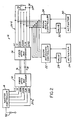
- master controller 14 and battery 52 carried by platform 16 are electrically isolated from controllers 22, 24 on vehicle base 34 by a pair of fiber optic bus extender modules 72, 74 (FIGS. 1 and 2) interconnected by a pair of optical fibers 76, 78 and inserted between the two sections 20a, 20b of bus 20. 20 to fibers 76, 78. Fibers 76, 78 extend through boom 18, and are extensible therewith. Extender module 74 is carried by vehicle base 34 and interfaces the signals on fibers 76, 78 with bus 20 connected to controllers 22, 24. Thus, the electronics on platform 16 are electrically isolated from the electronics on vehicle base 34, including base electrical ground. The boom extension and angle controllers are powered by separate batteries 79.
- a differential transmission bus interface driver 80 preferably an RS485 driver, has differential data ports connected to the COM and /COM differential data lines of bus 20.
- the other signal ports (DI and RO) of driver 80 are respectively connected to a fiber optic transmitter 82 coupled to fiber 76, and a fiber optic receiver 84 coupled to fiber 78.
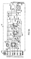
- the T/R control line of a bus 20 is connected within module 82 to the transmit/receive control ports (DE and /RE) of driver 80, and to the control input of a high frequency oscillator 86.
- oscillator 86 The output of oscillator 86 is connected through an isolation diode DR3 to optic transmitter 82 in parallel with the corresponding output port RO of driver 80 at the base of the drive transistor QR1. Extender module 72 is powered by battery 52 (FIGS. 1-3) through a voltage regulator 88. The control input of oscillator 86 is also connected to a capacitor CR5, which is connected through a resistor RR2 to the power supply for initiating operation of oscillator 86 upon application of battery power.
- bus extender module 74 also includes a differential transmission line driver 90 that has differential signal ports connected to the COM and /COM lines of bus 20, a transmission port RO connected through a transistor QB3 to a fiber optic transmitter 92, and a signal reception port DI connected to a fiber optic receiver 94. Transmitter 92 and receiver 94 are respectfully coupled to fibers 78, 76.
- a filter 96 is connected to the output of receiver 94 in parallel with the reception port of driver 90.
- Filter 96 includes a retriggerable one-shot 98 that has its output connected through a resistor RB4 and a capacitor CB5 to the base of a transistor QB2, which thus forms an integrator for the pulsed output of one-shot 98.
- a diode DB1 is connected in reverse polarity across resistor RB4 for rapidly discharging capacitor CB5 when one-shot 98 times out.
- the output of integrator 100 is connected to the transmit/receiver control ports (DE and /RE) of driver 90, and through an inverter 102 to the T/R line of bus 20.
- the T/R control line of bus 20 is normally high, and is brought low by any controller 14, 22, 24, seeking to transmit data, thereby alerting and conditioning the remaining controllers to receive information.
- This T/R function is maintained over the fiber optic bus extension in accordance with the present invention.
- the T/R control line of extender module 72 (FIG. 5A) is normally high, enabling operation of oscillator 86 and transmission of a high frequency pulsed periodic signal to module 74 through coupler 82 and fiber 76.
- driver 80 is conditioned to receive any data transmitted from extension and angle controllers 22, 24 (FIG. 2), and to retransmit such data to master controller 14 along the isolated bus section.
- oscillator 86 continually retriggers one-shot 98 (FIG. 5B) of extender module 74, so that the output of integrator 100 is low and the output of inverter 102 is high, thereby replicating the high state of the T/R line at the isolated bus section in the corresponding line of the main bus section.
- the low output of integrator 100 conditions driver 90 to receive data on the COM and /COM lines, and to transmit such data through driver 92 and fiber 78 to receiver 84 of module 72 (FIG. 5A).
- oscillator 86 has an output frequency in excess of the maximum design data transmission frequency of bus 20, preferably about two megahertz.
- the corresponding cutoff frequency of filter 96 is one megahertz.
- the bus extender is thus normally configured to transmit data in one direction, specifically from device controllers 22, 24 to master controller 14. If either controller 22, 24 brings its T/R line low, extender modules 72, 74 are unaffected.
- driver 80 (FIG. 5A) of extender module 72 is correspondingly conditioned to transmit signals at the COM and /COM ports to transmitter 82.
- a low input to oscillator 86 inhibits oscillator operation, thereby terminating the high frequency periodic signal to the input of retriggerable one-shot 98 (FIG. 5B).
- one shot 98 times out, and the Q output thereof to integrator 100 goes low, the integrator is rapidly discharged though diode DB1 so that the output of transistor QB2 assumes a high state.
- Driver 90 is thereby conditioned to receive data from receiver 94 and place such data signals on the COM and /COM lines of bus 20.
- the T/R control line of bus 20 is brought low by inverter 102, thereby conditioning boom extension controller 22 (FIG. 2) and boom angle controller 24 to receiver data from master controller 14.
- Data transmission is well below the retrigger period of one-shot 98.
- Diode DB1 ensures that compacitor CB5 discharges between data signals, so that the collector of transistor QB2 remains high.
- circuits of modules 72, 74 are similar in many respects.
- circuitboards are designed to accommodate either circuit, which reduces necessary part inventory.
Landscapes
- Engineering & Computer Science (AREA)
- Structural Engineering (AREA)
- Life Sciences & Earth Sciences (AREA)
- Geology (AREA)
- Mechanical Engineering (AREA)
- Selective Calling Equipment (AREA)
- Forklifts And Lifting Vehicles (AREA)
- Optical Communication System (AREA)
- Arrangements For Transmission Of Measured Signals (AREA)
Applications Claiming Priority (2)
| Application Number | Priority Date | Filing Date | Title |
|---|---|---|---|
| US07/364,871 US4917213A (en) | 1989-06-12 | 1989-06-12 | Power transmission |
| US364871 | 1989-06-12 |
Publications (3)
| Publication Number | Publication Date |
|---|---|
| EP0402813A2 true EP0402813A2 (fr) | 1990-12-19 |
| EP0402813A3 EP0402813A3 (fr) | 1992-10-28 |
| EP0402813B1 EP0402813B1 (fr) | 1995-09-06 |
Family
ID=23436445
Family Applications (1)
| Application Number | Title | Priority Date | Filing Date |
|---|---|---|---|
| EP90110957A Expired - Lifetime EP0402813B1 (fr) | 1989-06-12 | 1990-06-09 | Transmission de puissance |
Country Status (5)
| Country | Link |
|---|---|
| US (1) | US4917213A (fr) |
| EP (1) | EP0402813B1 (fr) |
| JP (1) | JP2693852B2 (fr) |
| CN (1) | CN1036542C (fr) |
| DE (1) | DE69022123T2 (fr) |
Cited By (3)
| Publication number | Priority date | Publication date | Assignee | Title |
|---|---|---|---|---|
| DE4405594A1 (de) * | 1994-02-22 | 1995-08-24 | Paul Lingen | Anbaukran für ein fahrbares Arbeitsgerät |
| WO2001069817A1 (fr) * | 2000-03-11 | 2001-09-20 | Opticis Co., Ltd. | Module d'interface de communication optique connecte a un module d'interface de communication electrique de protocole de communication i2c |
| DE202005020462U1 (de) * | 2005-12-08 | 2007-04-19 | Liebherr-Werk Ehingen Gmbh | Kran |
Families Citing this family (14)
| Publication number | Priority date | Publication date | Assignee | Title |
|---|---|---|---|---|
| DE69739160D1 (de) * | 1996-10-18 | 2009-01-22 | Yaskawa Denki Seisakusho Kk | Autonomes roboterfahrzeug für arbeiten and spannungsführenden stromleitungen |
| JPH11343642A (ja) * | 1998-06-01 | 1999-12-14 | Kobe Steel Ltd | バッテリー駆動式作業機械 |
| SG82672A1 (en) * | 1999-02-04 | 2001-08-21 | Snorkel International Inc | Aerial work platform boom having ground and platform controls linked by a controller area network |
| DE202004008083U1 (de) * | 2004-05-19 | 2005-11-10 | Liebherr-Werk Ehingen Gmbh | Mobilkran |
| US10358331B2 (en) | 2010-12-20 | 2019-07-23 | Jlg Industries, Inc. | Work platform with protection against sustained involuntary operation |
| JP4850048B2 (ja) * | 2006-12-08 | 2012-01-11 | 全日空モーターサービス株式会社 | ボーディングブリッジの装着方法 |
| JP4850047B2 (ja) * | 2006-12-08 | 2012-01-11 | 全日空モーターサービス株式会社 | ボーディングブリッジ |
| CN101458869B (zh) * | 2007-12-14 | 2011-04-20 | 瑞轩科技股份有限公司 | 使用光纤的遥控设备 |
| US20100200328A1 (en) * | 2009-02-06 | 2010-08-12 | Conception Gsr Inc. | Hydraulic boom system for vehicle |
| US10124999B2 (en) * | 2010-12-20 | 2018-11-13 | Jlg Industries, Inc. | Opto-electric system of enhanced operator control station protection |
| US10029899B2 (en) | 2010-12-20 | 2018-07-24 | Jlg Industries, Inc. | Work platform with protection against sustained involuntary operation |
| US10151895B2 (en) * | 2014-08-13 | 2018-12-11 | Altec Industries, Inc. | System and method of transmitting electricity through an insulated environment |
| US10794079B2 (en) | 2016-02-24 | 2020-10-06 | Terex Usa, Llc | System and method for installing a cross arm on a utility pole |
| FR3056203B1 (fr) * | 2016-09-21 | 2020-10-09 | Haulotte Group | Assistance visuelle au deplacement au sol d'une nacelle elevatrice |
Family Cites Families (6)
| Publication number | Priority date | Publication date | Assignee | Title |
|---|---|---|---|---|
| US3844378A (en) * | 1971-07-26 | 1974-10-29 | Mccabe Powers Body Co | Control system for an aerial device |
| US4044856A (en) * | 1975-07-25 | 1977-08-30 | General Cable Corporation | Lifting equipment having a boom structure and a control mechanism for use therewith using a flexible light guide |
| US4744218A (en) * | 1986-04-08 | 1988-05-17 | Edwards Thomas L | Power transmission |
| US4757747A (en) * | 1986-04-08 | 1988-07-19 | Vickers, Incorporated | Power transmission |
| WO1988001085A2 (fr) * | 1986-08-06 | 1988-02-11 | Westinghouse Electric Corporation | Liaison de communication a fibre optique pour vehicule mobile a distance |
| US4811195A (en) * | 1987-03-04 | 1989-03-07 | Asi Controls | Electronic control system with improved communications |
-
1989
- 1989-06-12 US US07/364,871 patent/US4917213A/en not_active Expired - Lifetime
-
1990
- 1990-06-04 JP JP2146062A patent/JP2693852B2/ja not_active Expired - Fee Related
- 1990-06-09 DE DE69022123T patent/DE69022123T2/de not_active Expired - Lifetime
- 1990-06-09 EP EP90110957A patent/EP0402813B1/fr not_active Expired - Lifetime
- 1990-06-12 CN CN90104488A patent/CN1036542C/zh not_active Expired - Fee Related
Cited By (5)
| Publication number | Priority date | Publication date | Assignee | Title |
|---|---|---|---|---|
| DE4405594A1 (de) * | 1994-02-22 | 1995-08-24 | Paul Lingen | Anbaukran für ein fahrbares Arbeitsgerät |
| WO2001069817A1 (fr) * | 2000-03-11 | 2001-09-20 | Opticis Co., Ltd. | Module d'interface de communication optique connecte a un module d'interface de communication electrique de protocole de communication i2c |
| US7043161B2 (en) | 2000-03-11 | 2006-05-09 | Opticis Co., Ltd | Optical communication interface module connected to electrical communication interface module of I2C communication protocol |
| DE202005020462U1 (de) * | 2005-12-08 | 2007-04-19 | Liebherr-Werk Ehingen Gmbh | Kran |
| US7665620B2 (en) | 2005-12-08 | 2010-02-23 | Liebherr-Werk Ehingen Gmbh | Crane |
Also Published As
| Publication number | Publication date |
|---|---|
| CN1048085A (zh) | 1990-12-26 |
| EP0402813A3 (fr) | 1992-10-28 |
| US4917213A (en) | 1990-04-17 |
| CN1036542C (zh) | 1997-11-26 |
| DE69022123T2 (de) | 1996-04-18 |
| DE69022123D1 (de) | 1995-10-12 |
| JPH0326700A (ja) | 1991-02-05 |
| JP2693852B2 (ja) | 1997-12-24 |
| EP0402813B1 (fr) | 1995-09-06 |
Similar Documents
| Publication | Publication Date | Title |
|---|---|---|
| US4917213A (en) | Power transmission | |
| US4804937A (en) | Vehicle monitoring arrangement and system | |
| US4745744A (en) | Power transmission | |
| US6548969B2 (en) | Redundant steer-by-wire system | |
| JPH02266628A (ja) | 通信回路網 | |
| JPH07113854B2 (ja) | 分散制御を備えた電気的油圧システム | |
| WO1998051454A1 (fr) | Systeme de commande de robot | |
| US7890236B2 (en) | Automated control module for a power machine | |
| WO2000043844A1 (fr) | Systeme de commande electronique d'une machine | |
| US6181096B1 (en) | Robot controlling system | |
| US6396030B1 (en) | Robot control device | |
| US20040094212A1 (en) | Device for actuating an articulated mast, especially for concrete pumps | |
| US5994861A (en) | Servo system | |
| EP0067228A1 (fr) | Unite de commande numerique | |
| EP0471840A1 (fr) | Machine a direction hydraulique de type a commande electronique | |
| WO1989000315A1 (fr) | Dispositif de commutation a modes multiples | |
| US4567415A (en) | System for controlling the movement of an industrial manipulator | |
| KR870000295B1 (ko) | 차량의 정보 전송장치 | |
| EP0797134A1 (fr) | Unites d'e/s et tableau de commande pour controleurs numeriques | |
| EP1837131A1 (fr) | Manipulateur, par example pour un robot industriel, et dispositif d'entraînement pour un manipulateur | |
| EP1533771A1 (fr) | Procédé et système pour commander des machines-outils et véhicules industriels | |
| KR0135322B1 (ko) | 공작기계 직렬 입출력 신호 레벨 변환장치 | |
| JPH0686101U (ja) | 農業機械におけるコントローラ | |
| WO2025133082A1 (fr) | Robot mobile à adaptateur configurable | |
| CN116449753A (zh) | 物流移动机器人的运动控制器及系统 |
Legal Events
| Date | Code | Title | Description |
|---|---|---|---|
| PUAI | Public reference made under article 153(3) epc to a published international application that has entered the european phase |
Free format text: ORIGINAL CODE: 0009012 |
|
| AK | Designated contracting states |
Kind code of ref document: A2 Designated state(s): DE FR GB IT SE |
|
| PUAL | Search report despatched |
Free format text: ORIGINAL CODE: 0009013 |
|
| AK | Designated contracting states |
Kind code of ref document: A3 Designated state(s): DE FR GB IT SE |
|
| 17P | Request for examination filed |
Effective date: 19930416 |
|
| 17Q | First examination report despatched |
Effective date: 19940607 |
|
| ITF | It: translation for a ep patent filed | ||
| GRAA | (expected) grant |
Free format text: ORIGINAL CODE: 0009210 |
|
| AK | Designated contracting states |
Kind code of ref document: B1 Designated state(s): DE FR GB IT SE |
|
| REF | Corresponds to: |
Ref document number: 69022123 Country of ref document: DE Date of ref document: 19951012 |
|
| ET | Fr: translation filed | ||
| PLBE | No opposition filed within time limit |
Free format text: ORIGINAL CODE: 0009261 |
|
| STAA | Information on the status of an ep patent application or granted ep patent |
Free format text: STATUS: NO OPPOSITION FILED WITHIN TIME LIMIT |
|
| 26N | No opposition filed | ||
| PGFP | Annual fee paid to national office [announced via postgrant information from national office to epo] |
Ref country code: FR Payment date: 19970521 Year of fee payment: 8 |
|
| PG25 | Lapsed in a contracting state [announced via postgrant information from national office to epo] |
Ref country code: FR Free format text: LAPSE BECAUSE OF NON-PAYMENT OF DUE FEES Effective date: 19990226 |
|
| REG | Reference to a national code |
Ref country code: FR Ref legal event code: ST |
|
| REG | Reference to a national code |
Ref country code: GB Ref legal event code: IF02 |
|
| PG25 | Lapsed in a contracting state [announced via postgrant information from national office to epo] |
Ref country code: IT Free format text: LAPSE BECAUSE OF NON-PAYMENT OF DUE FEES;WARNING: LAPSES OF ITALIAN PATENTS WITH EFFECTIVE DATE BEFORE 2007 MAY HAVE OCCURRED AT ANY TIME BEFORE 2007. THE CORRECT EFFECTIVE DATE MAY BE DIFFERENT FROM THE ONE RECORDED. Effective date: 20050609 |
|
| PGFP | Annual fee paid to national office [announced via postgrant information from national office to epo] |
Ref country code: SE Payment date: 20090605 Year of fee payment: 20 |
|
| PGFP | Annual fee paid to national office [announced via postgrant information from national office to epo] |
Ref country code: DE Payment date: 20090630 Year of fee payment: 20 Ref country code: GB Payment date: 20090507 Year of fee payment: 20 |
|
| REG | Reference to a national code |
Ref country code: GB Ref legal event code: PE20 Expiry date: 20100608 |
|
| EUG | Se: european patent has lapsed | ||
| PG25 | Lapsed in a contracting state [announced via postgrant information from national office to epo] |
Ref country code: GB Free format text: LAPSE BECAUSE OF EXPIRATION OF PROTECTION Effective date: 20100608 |
|
| PG25 | Lapsed in a contracting state [announced via postgrant information from national office to epo] |
Ref country code: DE Free format text: LAPSE BECAUSE OF EXPIRATION OF PROTECTION Effective date: 20100609 |