EP0402783A2 - Reaktor - Google Patents
Reaktor Download PDFInfo
- Publication number
- EP0402783A2 EP0402783A2 EP90110862A EP90110862A EP0402783A2 EP 0402783 A2 EP0402783 A2 EP 0402783A2 EP 90110862 A EP90110862 A EP 90110862A EP 90110862 A EP90110862 A EP 90110862A EP 0402783 A2 EP0402783 A2 EP 0402783A2
- Authority
- EP
- European Patent Office
- Prior art keywords
- basket
- reactor
- baskets
- bed
- jacket
- Prior art date
- Legal status (The legal status is an assumption and is not a legal conclusion. Google has not performed a legal analysis and makes no representation as to the accuracy of the status listed.)
- Granted
Links
Images


Classifications
-
- B—PERFORMING OPERATIONS; TRANSPORTING
- B01—PHYSICAL OR CHEMICAL PROCESSES OR APPARATUS IN GENERAL
- B01J—CHEMICAL OR PHYSICAL PROCESSES, e.g. CATALYSIS OR COLLOID CHEMISTRY; THEIR RELEVANT APPARATUS
- B01J8/00—Chemical or physical processes in general, conducted in the presence of fluids and solid particles; Apparatus for such processes
- B01J8/02—Chemical or physical processes in general, conducted in the presence of fluids and solid particles; Apparatus for such processes with stationary particles, e.g. in fixed beds
- B01J8/0207—Chemical or physical processes in general, conducted in the presence of fluids and solid particles; Apparatus for such processes with stationary particles, e.g. in fixed beds the fluid flow within the bed being predominantly horizontal
- B01J8/0214—Chemical or physical processes in general, conducted in the presence of fluids and solid particles; Apparatus for such processes with stationary particles, e.g. in fixed beds the fluid flow within the bed being predominantly horizontal in a cylindrical annular shaped bed
-
- B—PERFORMING OPERATIONS; TRANSPORTING
- B01—PHYSICAL OR CHEMICAL PROCESSES OR APPARATUS IN GENERAL
- B01J—CHEMICAL OR PHYSICAL PROCESSES, e.g. CATALYSIS OR COLLOID CHEMISTRY; THEIR RELEVANT APPARATUS
- B01J2208/00—Processes carried out in the presence of solid particles; Reactors therefor
- B01J2208/00796—Details of the reactor or of the particulate material
- B01J2208/00823—Mixing elements
- B01J2208/00831—Stationary elements
- B01J2208/00849—Stationary elements outside the bed, e.g. baffles
-
- B—PERFORMING OPERATIONS; TRANSPORTING
- B01—PHYSICAL OR CHEMICAL PROCESSES OR APPARATUS IN GENERAL
- B01J—CHEMICAL OR PHYSICAL PROCESSES, e.g. CATALYSIS OR COLLOID CHEMISTRY; THEIR RELEVANT APPARATUS
- B01J2208/00—Processes carried out in the presence of solid particles; Reactors therefor
- B01J2208/00796—Details of the reactor or of the particulate material
- B01J2208/00884—Means for supporting the bed of particles, e.g. grids, bars, perforated plates
Definitions
- the invention relates to a reactor which is constructed essentially cylindrically symmetrically about an essentially vertical axis and has a jacket and within the jacket an annular bed which is filled with free-flowing material and by an inner and an outer basket, and on its underside is bounded by a bottom supported on the jacket from below, both baskets being rigidly connected in the radial direction and rigidly connected to the jacket on their underside.
- reactors There is a wide range of applications for such reactors. They can be used for a wide variety of reactions between a gas and an active material that is in free-flowing form.
- the active material can be, for example, an adsorbent or a catalyst.
- the reactor can contain several types of active material and can consist of more than one bed. In this case, one bed is concentrically enclosed by the neighboring one.
- a reaction gas is guided approximately radially to the axis of symmetry of the reactor through the bed filled with active, free-flowing material, for example by supplying it to the space between the jacket and the outer basket and withdrawing it from the space inside the inner basket.
- active material adsorbent
- the adsorbent must be regenerated at regular intervals.
- a regeneration gas which has a different chemical composition and / or a different thermodynamic state than the one to be cleaned is passed through the bed of active material.
- the reaction can e.g. consist in an adsorptive separation of gas mixtures or in an adsorptive removal of undesired components from a gas to be cleaned.
- a practical example of the latter is the separation of water and / or carbon dioxide from air, which is fed to a cryogenic air separation plant.
- the free-flowing material which is introduced into the bulk bed acts in this case as an adsorbent and can consist, for example, of a molecular sieve.
- a reactor of the type mentioned in the introduction can also be used for catalytic reactions, for example for removing NO x from the exhaust gas from combustion plants.
- the free-flowing bed material in this case consists, for example, of metal-doped molecular sieve particles.
- a central problem in the construction of a reactor of this type is the large temperature differences between the various operating phases spatial temperature gradients within the bed.
- the associated thermal changes in length of the baskets in the radial and axial directions already lead to major mechanical problems in normal operation due to relative movements between free-flowing material and the baskets. This is associated, for example, with undesired abrasion of the bulk material. Even more, there can be major mechanical damage in the event of malfunctions and the associated greater temperature fluctuations. Similar problems also arise when the reactor is used for catalytic reactions, particularly in the start-up phase and in the event of operational malfunctions.
- the baskets can expand in the axial direction when heated and contract again when they cool down. This avoids that mechanical stresses due to the thermal changes in length have the effect that the radial dimensions of the bed change and the bulk material sags.
- the axial movement always causes undesirable abrasion of the free-flowing material and also harbors the risk of warping within the bed in the case of extremely high temperature fluctuations.
- the free-flowing material is therefore still subject to wear and operating malfunctions are associated with the risk of major damage to the reactor and the bed.
- the economy of the known reactor is limited by the frequent changes in the bed and by repair work to remove damage occurring during operation.
- the invention is therefore based on the object of further developing the reactor of the type mentioned at the outset, that a particularly safe and economical operation is made possible and, in particular, damage to free-flowing material and reactor - both in normal operation and in the event of malfunctions - is largely avoided.
- a body that is rigid in a certain direction is quite capable of e.g. expand with temperature changes.
- a corrugated sheet is rigid in the direction of the troughs and stretchable in the direction perpendicular to it.
- a corrugated sheet bent on a cylinder jacket, in which the troughs run in circles around the cylinder axis, is expandable in the axial direction and rigid in the tangential and thus also in the radial direction.
- a spiral spring can also be referred to as axially stretchable and radially rigid in this sense.
- the design according to the invention is based on the idea of largely avoiding relative movements between the free-flowing material and at least one basket in the axial direction. This is achieved through two features.
- the rigid attachment of the basket at both ends means that the geometric length of the basket is virtually independent of the temperature conditions inside the reactor. This measure is determined by the height of the jacket, which itself is hardly exposed to changes in temperature. The ends of the basket are prevented from temperature-induced movements by this rigid attachment.
- the axial extensibility of the basket absorbs the expansion of the material when the temperature rises over the entire length of the basket, so that temperature-dependent displacements cannot occur at any point.
- the avoidance of displacements in turn means that - even with large temperature fluctuations - there are practically no relative movements between the bed and the basket and the reactor can thus be operated particularly safely.
- the increase in safety means that operational interruptions are largely avoided and the reactor as a whole is highly economical.
- the reactor according to the invention uses a much smaller amount complicated structure prevents the unwanted relative movement. Extensive tests and calculations have shown that, contrary to the fears previously held, it is entirely possible to process temperature differences of up to approx. 300 K without damage to the reactor and the bed.
- the baskets or baskets When installing the reactor, which takes place at ambient temperature, the baskets or baskets may be placed under axial tension.
- the degree of preload depends on the height of the temperature gradient across the bed.
- the temperature tolerance of the material is initially compensated for by a reduction in the preload.
- the preload is preferably dimensioned such that approximately half of the expected axial temperature expansion can be compensated for by reducing the preload. Only at a higher temperature is the pretension completely reduced and the temperature-related expansion of the material has to be absorbed as a compression due to the axial extensibility of the shape of the baskets. In this way, the compressive forces acting in the axial direction are considerably reduced and safe operation of the reactor is ensured even at a higher temperature.
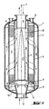
- Figure 1 shows the basic structure of the exemplary embodiment of the reactor according to the invention with its essential features.
- the representation is very schematic, in particular the relationships between the outer dimensions of the reactor and the material thicknesses do not correspond to the actual dimensions.
- the reactor is essentially cylindrical symmetrical about axis 1. It is delimited on the outside by a jacket 2, which has an upper 7 and a lower cap 8 with inlet 10 and outlet openings 9 for gas to be cleaned.
- the upper cap 7 is also broken through nozzle 11 for filling and suction of free-flowing material.
- annular adsorption bed 3 Arranged in the interior of the reactor is an annular adsorption bed 3, which is delimited by two cylinder-shell-shaped baskets, an outer 5 and an inner 4.
- the bed 3 is closed at the bottom by the bottom 6, which is rigidly attached to the lower calotte 8 of the jacket 2 via ribs 12 arranged in a star shape.
- the inner basket 4 is rigidly connected to the bottom 6 at its lower end. It is also supported by the ribs 12 arranged in a star shape on the lower cap 8 of the casing 2.
- the outer basket 5 stands on the lower cap 8, is welded to it and thus rigidly connected to the jacket 2.
- the baskets 4, 5 are made of perforated sheet metal for the most part.
- the holes are indicated in Figure 1 by horizontal lines (not to scale). Unperforated sheet metal is only used at the ends. Details of the structure of the baskets 4, 5 can be found in FIGS. 2 and 3 and the associated description text.
- the direction of flow of the gas to be purified is indicated in Figure 1 by arrows with solid lines (reaction or adsorption phase).
- the gas to be cleaned for example air, flows into the reactor via the inlet opening 10, is deflected through the underside of the base 6 and drip-off water is separated off in the process.
- the gas to be cleaned is then passed into the outer annular space 15 between the jacket 2 and the outer basket 5. From there, the gas to be cleaned flows with a radial component through the adsorption bed 3 into the inner annular space 16.
- this is also limited by a displacement body 17 constructed from truncated cones, which reduces the cross section of the inner annular space 16. This ensures an approximately uniform current density of the gas to be cleaned in bed 3, largely independently of the axial coordinate.
- a dust screen 13 is provided between the inner basket 4 and the displacement body 17 if necessary.
- a regeneration gas for example nitrogen, is conducted in the opposite direction during the regeneration phase (dashed arrows in FIG. 1).
- Figure 2 shows the detail A of Figure 1 in detail, on which the upper attachment of the outer basket 5 to the upper cap 7 of the shell 2 can be seen.
- the upper part of the outer basket 5 made of non-perforated sheet metal 18 is rigidly connected to the upper cap 7 by means of two annular weld seams 19.
- the inner basket 4 is welded to the upper cap 7 of the casing 2 in the same way.
- the attachment of the lower end of the outer basket 5 to the lower cap 8 is carried out analogously.
- the elongated holes 25 in the sheet metal 20 are regularly arranged in circles around the axis of symmetry 1. Their dimensions and their configuration are determined depending on the temperature gradient to be expected. In the present example, the hole width is 3 mm, the hole length is 30 mm and the web width (lateral distance between holes of two adjacent circles) is 6 mm (see FIG. 3). If the particle size of the bulk material is smaller than the hole width, both baskets 4, 5 have a wire mesh 22 on their side facing the interior of the bed 3, as shown in FIG. 3 with reference to the outer basket 5.
- the configuration of the perforated plate 20 defines the essential properties of the baskets for the invention. This is explained using the processing shown in FIG. 3.
- the horizontal in the drawing corresponds to a tangential direction around the axis of symmetry of the reactor, the vertical corresponds to the axial direction.
- the perforated plate has continuous webs in the tangential direction and therefore behaves along the direction of the webs similarly to an unperforated material. In this sense, the perforated plate 20 behaves rigidly in the tangential direction.
- the basket which essentially consists of a perforated plate in the form of a cylindrical jacket, is thus radially rigid.
- the perforated plate 20 In the axial direction, the perforated plate 20 has no webs that are continuous on a straight line, but is repeatedly interrupted by holes. It is therefore compressible and stretchable in this direction. Forces in the axial direction can be absorbed not only by the elasticity of the material, but also by changing the shape of the perforated plate 20, for example by distorting the shape of the holes 25.
- FIG. 4 shows a projection of a section of the cylindrical surface of a basket
- FIG. 5 shows a section along an axial line; the axis of symmetry of the reactor is vertical in the figures.
- Both basket types are perforated, generally stamped, sheet metal with a thickness d of 2 to 10, preferably 2.5 to 6.0 mm.
- the holes are elongated, with their longer side aligned along the horizontal (the horizontal in the drawings) and arranged in circles around the axis of symmetry of the reactor.
- a vertically continuous web (30a, 30b) that is not interrupted by holes is located between two adjacent circles.
- the baskets are therefore on the one hand along the circles (tangential) and thus radially rigid overall and on the other hand can accommodate axial changes in length by bending the holes (axially expandable in the sense of the invention).
- Basket type of figure 3 Length of holes a: 20 to 50 mm, preferably 25 to 35 mm Width of the holes b: 2 to 5 mm, preferably 2.5 to 3.5 mm horizontal web width c h : 4 to 8 mm, preferably 5.0 to 7.0 mm vertical web width c v : 5 to 20 mm, preferably 8.0 to 12.0 mm Basket type of Figures 4 and 5: Length of holes a: 10 to 40 mm, preferably 20 to 30 mm Width of the holes b: 0.8 to 2.0 mm, preferably 1.0 to 1.5 mm horizontal web width c h : 3.0 to 10 mm, preferably 4.0 to 6.0 mm vertical web width c v : 3.0 to 12 mm, preferably 5.0 to 7.0 mm
- the smaller dimensions of the holes in the second embodiment mean that an additional fine-mesh wire mesh on the inside of the basket (on the right in FIG. 5) can generally be dispensed with, since the adsorbent or catalyst particles are retained solely by the perforated sheet will.
- FIGS. 6 and 7 show in a similar view a third basket version with which the invention can be implemented. This is constructed completely differently, namely as wire mesh.
- Circular, horizontal wires 40a, 40b, 40c are interwoven with vertical (axial) wires 41a, 41b, 41c.
- the horizontal wires 40a, 40b, 40C do not have any significant bends and thus (similar to the continuous webs 30a, 30b of the previous example) bring about the radial rigidity of the basket.
- the vertical wires 41a, 41b, 41c are provided with bends, so-called joints, 42 at regular intervals of two mesh sizes. These can change their shape in the event of tensile or tensile stresses in the vertical (axial) direction and thus compensate for temperature-induced changes in length.
- the basket realized as a wire mesh is radially rigid and axially stretchable in the sense of the invention due to its special weave.
- the wire thickness is generally between 1.0 and 10 mm, preferably between 1.0 and 5.0 mm, most preferably between 2.0 and 3.0 mm.
Landscapes
- Chemical & Material Sciences (AREA)
- Physics & Mathematics (AREA)
- Fluid Mechanics (AREA)
- Organic Chemistry (AREA)
- Chemical Kinetics & Catalysis (AREA)
- Devices And Processes Conducted In The Presence Of Fluids And Solid Particles (AREA)
- Physical Or Chemical Processes And Apparatus (AREA)
- Treatment Of Water By Oxidation Or Reduction (AREA)
- Separation Of Gases By Adsorption (AREA)
- Organic Low-Molecular-Weight Compounds And Preparation Thereof (AREA)
Abstract
Description
- Die Erfindung betrifft einen Reaktor, der im wesentlichen zylindersymmetrisch um eine im wesentlichen vertikal verlaufende Achse aufgebaut ist und einen Mantel und innerhalb des Mantels ein ringförmiges Bett aufweist, welches mit rieselfähigem Material gefüllt ist und durch einen inneren und einen äußeren Korb, sowie an seiner Unterseite durch einen von unten her am Mantel abgestützten Boden begrenzt ist, wobei beide Körbe in radialer Richtung starr und an ihrer Unterseite starr mit dem Mantel verbunden sind.
- Für derartige Reaktoren besteht ein weiter Anwendungsbereich. Sie können für die verschiedensten Reaktionen zwischen einem Gas und einem aktiven Material, welches in rieselfähiger Form vorliegt, eingesetzt werden. Das aktive Material kann beispielsweise ein Adsorbens oder ein Katalysator sein. Der Reaktor kann mehrere Arten von aktivem Material enthalten und aus mehr als einem Bett bestehen. Ein Bett wird in diesem Fall vom benachbarten konzentrisch umschlossen.
- Während der Reaktionsphase wird ein Reaktionsgas in etwa radial zur Symmetrieachse des Reaktors durch das mit aktivem, rieselfähigem Material gefüllte Bett geführt, indem es beispielsweise dem Raum zwischen Mantel und äußerem Korb zugeleitet und von dem Raum innerhalb des inneren Korbes wieder abgezogen wird. Im Falle einer Adsorptionsreaktion nimmt die Reaktionsfähigkeit des aktiven Materials (Adsorbens) mit zunehmender Reaktionsdauer ab. Daher muß das Adsorbens in regelmäßigen Zeitabständen regeneriert werden. Während der Regenerierphase wird ein Regeneriergas, das gegenüber dem zu reinigenden eine andere chemische Zusammensetzung und/oder einen anderen thermodynamischen Zustand aufweist, durch die Schüttung aus aktivem Material geleitet.
- Die Reaktion kann z.B. in einer adsorptiven Trennung von Gasgemischen oder in einer adsorptiven Entfernung von unerwünschten Bestandteilen aus einem zu reinigenden Gas bestehen. Ein praktisches Beispiel für letzteres ist die Abscheidung von Wasser und/oder Kohlendioxid aus Luft, die einer Tieftemperaturluftzerlegungsanlage zugeführt wird. Das rieselfähige Material, welches in das Schüttbett eingebracht wird, wirkt in diesem Falle als Adsorbens und kann beispielsweise aus einem Molekularsieb bestehen.
- Während der Reaktions- bzw. Adsorptionsphase wird zu reinigende Luft durch das Bett geführt und dabei Wasser und/oder Kohlendioxid an das aktive Material abgegeben. Während der Regenerierphase werden die aus der Luft entfernten Stoffe wieder desorbiert, indem ein Regeneriergas, beispielsweise Stickstoff, durch das Bett mit dem Adsorbens geleitet wird. Dabei herrschen im allgemeinen andere Temperaturen und/oder Drücke als während der Adsorptionsphase.
- Ein Reaktor der eingangs genannte Art kann außer dem für katalytische Reaktionen eingesetzt werden, beispielsweise zur Entfernung von NOx aus dem Abgas von Verbrennungsanlagen. Das rieselfähige Bettmaterial besteht in diesem Fall zum Beispiel aus metalldotierten Molekularsieb-Teilchen.
- Ein zentrales Problem bei der Konstruktion eines Reaktors dieser Art besteht in den großen Temperaturunterschieden zwischen den verschiedenen Betriebsphasen So strömt beispielsweise beim Regeneriervorgang - um bei dem Beispiel einer Adsorption zu bleiben - das Regeneriergas bei hoher Temperatur ein und bewirkt in kurzer Zeit eine hohe Temperaturänderung und große räumliche Temperaturgradienten innerhalb der Schüttung. Die damit verbundenen thermischen Längenänderungen der Körbe in radialer und axialer Richtung führen bereits im Normalbetrieb zu großen mechanischen Problemen durch Relativbewegungen zwischen rieselfähigem Material und den Körben. Damit ist beispielsweise ein unerwünschter Abrieb des Schüttgutes verbunden. Erst recht kann es bei Betriebsstörungen und damit verbundenen stärkeren Temperaturschwankungen zu großen mechanischen Schäden kommen. Ähnliche Probleme treten auch bei der Anwendung des Reaktors zu katalytischen Reaktionen auf, insbesondere in der Anfahrphase und bei Betriebsstörungen.
- Um diesen Schwierigkeiten zu begegnen, sind verschiedene Methoden entwickelt worden, mit den thermisch bedingten Längenänderungen der das Bett begrenzenden Körbe umzugehen. Einer dieser Vorschläge ist aus der AT-E-19 595 (Figur 4) bekannt. Dort wird bei einem Reaktor der eingangs genannten Art vorgeschlagen, die Körbe auf den Boden zu stellen und ihnen die Möglichkeit zur Ausdehnung nach oben einzuräumen. Die Körbe werden an ihrem oberen Ende lediglich mittels ringförmigen Führungswänden seitlich gesichert.
- Mit Hilfe dieser Konstruktion können sich die Körbe bei Erhitzung in axialer Richtung ausdehnen und bei Abkühlung wieder zusammenziehen. Damit wird vermieden, daß sich mechanische Spannungen aufgrund der thermischen Längenänderungen dahingehend auswirken, daß sich die radialen Abmessungen des Bettes verändern und das Schüttgut absackt. Die axiale Bewegung bewirkt jedoch immer einen unerwünschten Abrieb des rieselfähigen Materials und birgt außerdem bei extrem hohen Temperaturschwankungen die Gefahr von Verwerfungen innerhalb der Schüttung. Das rieselfähige Material ist also weiterhin Verschleiß ausgesetzt und Betriebsstörungen sind mit dem Risiko großer Schäden an Reaktor und Schüttung behaftet. Die Wirtschaftlichkeit des vorbekannten Reaktors wird durch relativ häufiges Wechseln der Schüttung und durch Reparaturarbeiten zur Beseitigung von während des Betriebes entstehenden Schäden eingeschränkt.
- Der Erfindung liegt daher die Aufgabe zugrunde, den Reaktor der eingangs genannten Art dahingehend weiter zu entwickeln,
daß ein besonders sicherer und wirtschaftlicher Betrieb ermöglicht wird und insbesondere Schäden an rieselfähigem Material und Reaktor - sowohl im Normalbetrieb als auch bei Störungen - weitgehend vermieden werden. - Diese Aufgabe wird dadurch gelöst, daß einer der beiden Körbe, welche das mit rieselfähigem Material gefüllte Bett begrenzen, in axialer Richtung dehnbar und an seiner Oberseite starr mit dem Mantel verbunden ist.
- Das Begriffspaar "starr" und "dehnbar" bezieht sich nicht auf die dem Material selbst innewohnenden Eigenschaften wie Elastizität oder Temperaturgängigkeit, sondern auf die Möglichkeit von Längenänderungen aufgrund der äußeren Form des Körpers, in diesem Fall eines Korbes. Ein in einer bestimmten Richtung starrer Körper ist in diesem Sinne durchaus fähig, sich z.B. bei Temperaturänderungen auszudehnen. Beispielsweise ist ein gewelltes Blech starr in Richtung der Wellentäler und dehnbar in der dazu senkrechten Richtung. Ein auf einen Zylindermantel gebogenes Wellblech, bei dem die Wellentäler auf Kreisen um die Zylinderachse verlaufen, ist in axialer Richtung dehnbar und in tangentialer und damit auch in radialer Richtung starr.
- Auch eine Spiralfeder kann in diesem Sinne als axial dehnbar und radial starr bezeichnet werden.
- Der erfindungsgemäßen Konstruktion liegt der Gedanke zugrunde, Relativbewegungen zwischem den rieselfähigen Material und mindestens einem Korb in axialer Richtung weitestgehend zu vermeiden. Dies wird durch zwei Merkmale erreicht. Zum einen bewirkt die starre Befestigung des Korbes an beiden Enden, daß die geometrische Länge des Korbes praktisch unabhängig von den Temperaturverhältnissen im Inneren des Reaktors festgelegt ist. Dieses Maß wird durch die Höhe des Mantels bestimmt, der selbst kaum Temperaturänderungen ausgesetzt ist. Die Enden des Korbes werden durch diese starre Befestigung an temperaturinduzierten Bewegungen gehindert. Zum zweiten fängt die axiale Dehnbarkeit des Korbes die Ausdehnung des Materials bei Temperaturerhöhungen über die gesamte Länge des Korbes auf, so daß an keiner Stelle temperaturabhängige Verschiebungen auftreten können.
- Die Vermeidung von Verschiebungen bedeutet wiederum, daß - auch bei großen Temperaturschwankungen - praktisch keine Relativbewegungen zwischen Schüttung und Korb auftreten und der Reaktor damit besonders sicher betrieben werden kann. Der Zuwachs an Sicherheit bewirkt eine weitgehende Vermeidung von Betriebsunterbrechungen und damit insgesamt eine hohe Wirtschaftlichkeit des Reaktors.
- Mit Hilfe dieser Konstruktion ist es möglich, die bei katalytischen und bei Adsorptionsreaktionen Temperaturunterschiede zu verarbeiten, ohne daß störende Relativbewegungen auftreten. Dazu muß für die Körbe selbstverständlich ein geeignetes Material mit einem Ausdehnungskoeffizienten, der mit demjenigen des rieselfähigen Materials in einem bestimmten Verhältnis steht, und eine geeignete Form von Korbblechen verwendet werden, etwa in der im Ausführungsbeispiel beschriebenen Art. Das Verhältnis der Temperaturausdehnungskoeffizienten von Korbmaterial zu Schüttmaterial liegt in etwa zwischen 0,25 und 2,5 , vorzugsweise zwischen ungefähr 1,0 und 2,0 .
- Während beim vorbekannten Stand der Technik komplizierte und aufwendige technische Maßnahmen angewandt werden, um die thermische Längenänderung des Materials der Körbe in eine Ausdehnung des gesamten Korbes umzusetzen und damit die Relativbewegung zwischen Schüttung und Korb sogar zu unterstützen, wird bei dem erfindungsgemäßen Reaktor mittels eines wesentlich weniger komplizierten Aufbaues die unerwünschte Relativbewegung verhindert. Umfangreiche Versuche und Berechnungen haben gezeigt, daß es entgegen der bisher gehegten Befürchtungen durchaus möglich ist, dabei Temperaturdifferenzen von bis zu ca. 300 K ohne Schäden für Reaktor und Schüttung zu verarbeiten.
- Dieser Vorteil kann gemäß einer günstigen Weiterbildung der Erfindung dadurch unterstützt werden, daß mindestens einer an der Oberseite starr mit dem Mantel verbundener Korb in axialer Richtung vorgespannt ist. Falls beide Körbe fest eingespannt, d.h. oben und unten starr mit dem Mantel verbunden sind, werden vorzugsweise beide Körbe vorgespannt.
- Bei der Montage des Reaktors, die bei Umgebungstemperatur stattfindet, werden der oder die Körbe gegebenenfalls unter axiale Spannung gesetzt. Das Maß der Vorspannung richtet sich nach der Höhe des Temperaturgradienten über die Schüttung. Bei Temperaturerhöhung, etwa durch erhitztes Regeneriergas, wird die Temperaturgängigkeit des Materials zunächst durch eine Verringerung der Vorspannung aufgefangen. Die Vorspannung wird dabei vorzugsweise so dimensioniert, daß etwa die Hälfte der zu erwartenden axialen Temperaturausdehnung durch den Abbau der Vorspannung kompensiert werden kann. Erst bei höherer Temperatur ist die Vorspannung vollständig abgebaut und die temperaturbedingte Ausdehnung des Materials muß als Stauchung durch die axiale Dehnbarkeit der Form der Körbe aufgefangen werden. Auf diese Weise werden die in axialer Richtung wirkenden Druckkräfte erheblich verringert und auch bei höherer Temperatur ist ein sicherer Betrieb des Reaktors gewährleistet.
- Die Erfindung wird nun anhand eines in den Zeichnungen dargestellten Ausführungsbeispiels näher erläutert.
- Hierbei zeigen:
- Figur 1 einen Schnitt durch den Reaktor des Ausführungsbeispiels entlang der Symmetrieachse in stark vereinfachter Darstellung,
- Figur 2 Ausschnitt A von Figur 1 im Detail,
- Figur 3 eine Abwicklung eines Korbes eines ersten Typs im Ausschnitt,
- Figuren 4, 5 einen Korb eines zweiten Typs in Abwicklungs- und Schnittdarstellung, sowie
- Figuren 6,7 einen Korb einer dritten Variante in Abwicklungs- und Schnittdarstellung.
- Figur 1 zeigt den prinzipiellen Aufbau der beispielhaften Ausführungsform des erfindungsgemäßen Reaktors mit seinen wesentlichen Merkmalen. Die Darstellung ist der Einfachheit halber sehr schematisch ausgeführt, insbesondere entsprechen die Verhältnisse zwischen den äußeren Abmessungen des Reaktors und den Materialdicken nicht den wirklichen Maßen.
- Der Reaktor ist im wesentlichen zylindersymmetrisch um die Achse 1 aufgebaut. Er wird nach außen begrenzt durch einen Mantel 2, welcher eine obere 7 und eine untere Kalotte 8 mit Eintritts- 10 und Austrittsöffnungen 9 für zu reinigendes Gas aufweist. Die obere Kalotte 7 ist außerdem durch Stutzen 11 zum Einfüllen und Absaugen von rieselfähigem Material durchbrochen.
- Im Inneren des Reaktors ist ein ringförmiges Adsorptionsbett 3 angeordnet, welches durch zwei zylindermantelförmige Körbe, einen äußeren 5 und einen inneren 4 begrenzt ist. Das Bett 3 wird nach unten hin durch den Boden 6 abgeschlossen, welcher über sternförmig angeordnete Rippen 12 starr an der unteren Kalotte 8 des Mantels 2 befestigt ist. Der innere Korb 4 ist an seinem unteren Ende starr mit dem Boden 6 verbunden. Er stützt sich ebenfalls über die sternförmig angeordneten Rippen 12 auf der unteren Kalotte 8 des Mantels 2 ab. Der äußere Korb 5 steht auf der unteren Kalotte 8 auf, ist mit dieser verschweißt und damit starr mit dem Mantel 2 verbunden.
- Die Körbe 4, 5 sind aus zum größten Teil gelochtem Blech gefertigt. Die Löcher sind in Figur 1 durch waagrechte Striche (nicht maßstäblich) angedeutet. Lediglich an den Enden ist auch ungelochtes Blech verwendet. Näheres über den Aufbau der Körbe 4, 5 ist den Figuren 2 und 3 und dem zugehörigen Beschreibungstext zu entnehmen.
- Innerhalb des Bettes 3 befindet sich eine Schüttung aus rieselfähigem Material. In der konkreten Verwendung des Reaktors handelt sich es um adsorptives Material, ebensogut könnte ein rieselfähiger Katalysator eingefüllt sein.
- Die Strömungsrichtung des zu reinigenden Gases wird in Figur 1 durch Pfeile mit durchgezogenen Linien angedeutet (Reaktions- bzw. Adsorptionsphase). Dabei strömt das zu reinigende Gas, beispielsweise Luft, über die Einlaßöffnung 10 in den Reaktor ein, wird durch die Unterseite des Bodens 6 umgelenkt und dabei tropfbares Wasser abgeschieden. Anschließend wird das zu reinigende Gas in den äußeren Ringraum 15 zwischen Mantel 2 und äußerem Korb 5 geleitet. Von dort strömt das zu reinigende Gas mit einer radialen Komponente durch das Adsorptionsbett 3 in den inneren Ringraum 16. Dieser wird außer durch den inneren Korb 4 auch durch einen aus Kegelstümpfen aufgebauten Verdrängungskörper 17 begrenzt, der den Querschnitt des inneren Ringraumes 16 verringert. Dadurch wird eine annähernd gleichmäßige Stromdichte des zu reinigenden Gases im Bett 3 weitgehend unabängig von der axialien Koordinate gewährleistet. Zwischen dem inneren Korb 4 und dem Verdrängungskörper 17 ist im Bedarfsfall ein Staubsieb 13 vorgesehen.
- Falls bei der Reaktion eine Regenerierung notwendig ist, wird während der Regenerierphase ein Regeneriergas, beispielsweise Stickstoff, in umgekehrter Richtung geführt (gestrichelte Pfeile in Figur 1).
- Figur 2 zeigt den Ausschnitt A von Figur 1 im Detail, auf dem die obere Befestigung des äußeren Korbes 5 an der oberen Kalotte 7 des Mantels 2 zu erkennen ist. Der obere, aus ungelochtem Blech 18 gearbeitete Teil des äußeren Korbes 5 ist mittels zweier ringförmiger Schweißnähte 19 starr mit der oberen Kalotte 7 verbunden. Bei der Bauweise des Ausführungsbeispiels ist der innere Korb 4 auf die gleiche Weise mit der oberen Kalotte 7 des Mantels 2 verschweißt. Die Befestigung des unteren Endes des äußeren Korbes 5 an der unteren Kalotte 8 ist analog ausgeführt.
- Die langgezogenen Löcher 25 im Blech 20 sind regelmäßig auf Kreisen um die Symmetrieachse 1 angeordnet. Ihre Abmessungen und ihre Konfiguration werden in Abhängigkeit von dem zu erwartenden Temperaturgradienten ermittelt. Im vorliegenden Beispiel betragen die Lochbreite 3 mm, die Lochlänge 30 mm und die Stegbreite (seitlicher Abstand zwischen Löchern zweier benachbarter Kreise) 6 mm (siehe Figur 3). Falls die Teilchengröße des Schüttgutes kleiner als die Lochbreite ist, weisen beide Körbe 4, 5 an ihrer dem Inneren des Bettes 3 zugewandten Seite ein Drahtnetz 22 auf, wie es in Figur 3 anhand des äußeren Korbes 5 gezeigt ist.
- Die Konfiguration des Lochblechs 20 legt die für die Erfindung wesentlichen Eigenschaften der Körbe fest. Dies sei anhand der in Figur 3 gezeigten Abwicklung erläutert. Die Horizontale in der Zeichnung entspricht einer tangentialen Richtung um die Symmetrieachse des Reaktors, die Vertikale der axialen Richtung. Zwischen jeweils zwei Reihen von Löchern weist das Lochblech in tangentialer Richtung durchgehende Stege auf und verhält sich deshalb entlang der Richtung der Stege ähnlich wie ein ungelochtes Material. In diesem Sinne verhält sich das Lochblech 20 starr in tangentialer Richtung. Der im wesentlichen aus einem zylindermantelförmigen Lochblechtell bestehende Korb ist damit radial starr. In axialer Richtung weist das Lochblech 20 keine auf einer Geraden durchgehende Stege auf, sondern wird immer wieder durch Löcher unterbrochen. Es ist daher in dieser Richtung stauchbar und dehnbar. In axialer Richtung anliegende Kräfte können nicht nur durch die Elastizität des Materials, sondern auch durch Änderung der Form des Lochbleches 20, etwa durch Verzerrung der Form der Löcher 25 aufgenommen werden.
- Figuren 4 und 5 zeigen eine gegenüber dem Korb der Figur 3 leicht abgewandelte zweite Ausführungsform. Figur 4 stellt eine Projektion eines Ausschnittes der Zylinderfläche eines Korbes dar, Figur 5 einen Schnitt entlang einer axialen Linie; die Symmetrieachse des Reaktors verläuft in den Figuren vertikal. Zunächst seien die gemeinsamen Merkmale der ersten beiden Ausführungsformen geschildert:
- Es handelt sich bei beiden Korbtypen um perforiertes, in der Regel gestanztes, Metallblech mit einer Stärke d von 2 bis 10, vorzugsweise 2,5 bis 6,0 mm. Die Löcher sind langgestreckt, mit ihrer längeren Seite entlang der Horizontalen (in den Zeichnungen die Waagerechte) ausgerichtet und auf Kreisen um die Symmetrieachse des Reaktors angeordnet. Zwischen jeweils zwei benachbarten Kreisen befindet sich ein vertikal durchgehender, also nicht durch Löcher unterbrochener Steg (30a, 30b). Die Löcher zweier horizontal benachbarten Kreise sind gegeneinander versetzt, so daß in axialer (=vertikaler) Richtung (Pfeile 31a, 31b) keine durchgehenden Stege vorhanden sind. Die Körbe sind daher einerseits entlang den Kreisen (tangential) und damit insgesamt radial starr und können andererseits axiale Längenänderungen durch Verbiegungen der Löcher aufnehmen (axial dehnbar im Sinne der Erfindung). Diese Eigenschaft ist in der speziellen Geometrie der Perforation begründet und qualitativ bei den ersten beiden Ausführungsformen identisch. Quantitative Unterschiede bestehen jedoch bei den Maßen der Löcher:
Korbtyp der Figur 3:
Länge der Löcher a:
20 bis 50 mm, vorzugsweise 25 bis 35 mm
Breite der Löcher b:
2 bis 5 mm, vorzugsweise 2,5 bis 3,5 mm
horizontale Stegbreite ch:
4 bis 8 mm, vorzugsweise 5,0 bis 7,0 mm
vertikale Stegbreite cv:
5 bis 20 mm, vorzugsweise 8,0 bis 12,0 mm
Korbtyp der Figuren 4 und 5:
Länge der Löcher a:
10 bis 40 mm, vorzugsweise 20 bis 30 mm
Breite der Löcher b:
0,8 bis 2,0 mm, vorzugsweise 1,0 bis 1,5 mm
horizontale Stegbreite ch:
3,0 bis 10 mm, vorzugsweise 4,0 bis 6,0 mm
vertikale Stegbreite cv:
3,0 bis 12 mm, vorzugsweise 5,0 bis 7,0 mm - Ein spezielles Ausführungsbeispiel gemäß Figuren 4 und 5 besitzt folgende Maße:
a = 25 mm
b = 1,2 mm
ch = 5,0 mm
cv = 6,0 mm
d = 4,0 mm - Die geringeren Maße der Löcher bei der zweiten Ausführungsform haben zur Folge, daß auf ein zusätzliches feinmaschiges Drahtnetz auf der Innenseite des Korbes (in Figur 5 rechts) in der Regel verzichtet werden kann, da die Adsorbens- bzw. Katalysatorteilchen allein durch das perforierte Blech zurückgehalten werden.
- Die Figuren 6 und 7 zeigen in ähnlicher Ansicht eine dritte Korbversion, mit welcher die Erfindung realisiert werden kann. Diese ist vollständig anders konstruiert, nämlich als Drahtgewebe.
- Kreisförmige, horizontale Drähte 40a, 40b, 40c sind dabei mit vertikalen (axialen) Drähten 41a, 41b, 41c verwoben. Die horizontalen Drähte 40a, 40b, 40C weisen dabei keine nennenswerten Biegungen auf und bewirken damit (ähnliche den durchgehenden Stegen 30a, 30b des vorhergehenden Beispiels) die radiale Starrheit des Korbes. Die vertikalen Drähte 41a, 41b, 41c sind jedoch in regelmäßigen Abständen von zwei Maschenweiten mit Ausbiegungen, sogenannten Gelenken, 42 versehen. Diese können bei Zug- oder Dehnspannungen in vertikaler (axialer) Richtung ihre Form ändern und damit temperaturinduzierte Längenänderungen kompensieren. Der als Drahtgitter realisierte Korb ist durch seine spezielle Webart radial starr und axial dehnbar im Sinne der Erfindung. Diese Eigenschaft kann durch die für die Drähte gewählten Materialien unterstützt werden. Dabei ist es vorteilhaft, wenn für die horizontalen Drähte 40a, 40b, 40C Invar-Stahl, für die vertikalen (axialen) Drähte 4la, 41b, 4lc CrNi-Stahl verwendet wird. Die Drahtdicke liegt im allgemeinen zwischen 1,0 und 10 mm, vorzugsweise zwischen 1,0 und 5,0 mm, höchst vorzugsweise zwischen 2,0 und 3,0 mm. Für die Maschenweite wird ein Maß zwischen 3,0 und 20 mm, vorzugsweise zwischen 6 und 12 mm gewählt.
- Da die Maschenweite im allgemeinen zu groß ist, um die Adsorbens- bzw. Katalysatorteilchen zurückzuhalten, muß an der Innenseite des Drahtgewebes (in Figur 7 links) zusätzlich ein feinmaschiges Drahtnetz angebracht werden. Dieses ist in den Figuren 6 und 7 nicht gezeigt. Innerhalb des Reaktors hat das Drahtnetz in etwa dieselbe vertikale Ausdehnung wie das Bett. Oberhalb und unterhalb wird der Korb analog zu Figur 1 über unperforiertes Blech starr mit dem Mantel verbunden.
Claims (4)
Priority Applications (1)
| Application Number | Priority Date | Filing Date | Title |
|---|---|---|---|
| AT90110862T ATE82159T1 (de) | 1989-06-16 | 1990-06-08 | Reaktor. |
Applications Claiming Priority (2)
| Application Number | Priority Date | Filing Date | Title |
|---|---|---|---|
| DE3919750A DE3919750A1 (de) | 1989-06-16 | 1989-06-16 | Reaktor |
| DE3919750 | 1989-06-16 |
Publications (3)
| Publication Number | Publication Date |
|---|---|
| EP0402783A2 true EP0402783A2 (de) | 1990-12-19 |
| EP0402783A3 EP0402783A3 (de) | 1991-02-27 |
| EP0402783B1 EP0402783B1 (de) | 1992-11-11 |
Family
ID=6382905
Family Applications (1)
| Application Number | Title | Priority Date | Filing Date |
|---|---|---|---|
| EP90110862A Expired - Lifetime EP0402783B1 (de) | 1989-06-16 | 1990-06-08 | Reaktor |
Country Status (14)
| Country | Link |
|---|---|
| US (1) | US5827485A (de) |
| EP (1) | EP0402783B1 (de) |
| JP (1) | JP2965625B2 (de) |
| AT (1) | ATE82159T1 (de) |
| AU (1) | AU629359B2 (de) |
| CA (1) | CA2028274C (de) |
| CZ (1) | CZ285430B6 (de) |
| DD (1) | DD301873A9 (de) |
| DE (2) | DE3919750A1 (de) |
| HU (1) | HU207241B (de) |
| PL (1) | PL285646A1 (de) |
| RU (1) | RU1809778C (de) |
| UA (1) | UA11069A (de) |
| ZA (1) | ZA904659B (de) |
Cited By (13)
| Publication number | Priority date | Publication date | Assignee | Title |
|---|---|---|---|---|
| EP0526343A1 (de) * | 1991-07-31 | 1993-02-03 | L'air Liquide S.A. | Adsorber mit übereinander angeordneten, ringförmigen Adsorptionsmittelbetten |
| EP0724906A1 (de) * | 1995-02-01 | 1996-08-07 | Fina Technology, Inc. | Reaktor und Verfahren zur Dehydrierung von Ethylbenzol zu Styrol |
| US5759242A (en) * | 1996-07-23 | 1998-06-02 | Praxair Technology, Inc. | Radial bed vaccum/pressure swing adsorber vessel |
| EP0897746A1 (de) * | 1997-08-14 | 1999-02-24 | Linde Aktiengesellschaft | Reaktor für chemische Reaktionen, insbesondere für adsorptive Trennverfahren |
| US6152992A (en) * | 1997-10-22 | 2000-11-28 | Linde Aktiengesellschaft | Reactor and process of using same |
| EP1892028A1 (de) * | 2006-08-07 | 2008-02-27 | Delphi Technologies, Inc. | Radiales Siebmodul |
| WO2009003663A1 (en) * | 2007-07-04 | 2009-01-08 | Ammonia Casale S.A. | Wall system for catalytic beds of synthesis reactors and relative production process |
| EP2448653A1 (de) * | 2009-06-29 | 2012-05-09 | Uop Llc | Gefäss, system und verfahren zur minimierung einer ungleichmässigen flussverteilung |
| FR3028426A1 (fr) * | 2014-11-14 | 2016-05-20 | Ifp Energies Now | Conduit de collecte pour un reacteur radial comprenant des filets pleins. |
| DE102015002260A1 (de) | 2015-02-25 | 2016-08-25 | Linde Aktiengesellschaft | Verfahren zum Herstellen eines horizontal durchströmten Adsorbers und Trennwandmodul zur Verwendung in diesem Verfahren |
| FR3056119A1 (fr) * | 2016-09-20 | 2018-03-23 | Total Raffinage Chimie | Paroi cylindrique de filtrage de particules solides dans un fluide |
| EP3318321A1 (de) | 2016-11-08 | 2018-05-09 | Linde Aktiengesellschaft | Verfahren zur herstellung einer adsorptionseinrichtung, umrüstverfahren für eine adsorptionseinrichtung und adsorptionseinrichtung |
| EP4052776A1 (de) * | 2021-03-05 | 2022-09-07 | L'Air Liquide, société anonyme pour l'Étude et l'Exploitation des procédés Georges Claude | Radialer adsorber mit radialer gaszirkulation |
Families Citing this family (44)
| Publication number | Priority date | Publication date | Assignee | Title |
|---|---|---|---|---|
| US4938422A (en) * | 1987-12-23 | 1990-07-03 | Uop | Inlet distributor for downflow reactor |
| US5855775A (en) | 1995-05-05 | 1999-01-05 | Kerfoot; William B. | Microporous diffusion apparatus |
| USRE43350E1 (en) | 1995-05-05 | 2012-05-08 | Think Village-Kerfoot, Llc | Microporous diffusion apparatus |
| DE19540537C1 (de) * | 1995-10-31 | 1997-06-26 | Uhde Gmbh | Vorrichtung zur Beaufschlagung einer Festkörperschüttung |
| US6245303B1 (en) * | 1998-01-14 | 2001-06-12 | Arthur D. Little, Inc. | Reactor for producing hydrogen from hydrocarbon fuels |
| US5814129A (en) * | 1997-04-11 | 1998-09-29 | Air Products And Chemical, Inc. | Radial flow adsorption vessel |
| US6086659A (en) * | 1999-01-29 | 2000-07-11 | Air Products And Chemicals, Inc. | Radial flow adsorption vessel |
| US6447676B1 (en) * | 1999-12-22 | 2002-09-10 | William B. Kerfoot | Springbox for water remediation |
| US6436285B1 (en) | 1999-12-22 | 2002-08-20 | William B. Kerfoot | Laminated microporous diffuser |
| US8557110B2 (en) | 2000-07-06 | 2013-10-15 | Thinkvillage-Kerfoot, Llc | Groundwater and subsurface remediation |
| US6582611B1 (en) | 2000-07-06 | 2003-06-24 | William B. Kerfoot | Groundwater and subsurface remediation |
| US6663839B2 (en) | 2001-02-26 | 2003-12-16 | Abb Lummus Global Inc. | Radial flow gas phase reactor and method for reducing the nitrogen oxide content of a gas |
| US20020132147A1 (en) * | 2001-03-16 | 2002-09-19 | Yong Gao | Chambered reactor for fuel processing |
| US7220341B2 (en) * | 2002-03-11 | 2007-05-22 | Exxonmobil Chemical Patents Inc. | Controlling solids flow in a gas-solids reactor |
| US8302939B2 (en) * | 2003-02-12 | 2012-11-06 | Thinkvillage-Kerfoot, Llc | Soil and water remediation system and method |
| US6913251B2 (en) | 2003-02-12 | 2005-07-05 | William B. Kerfoot | Deep well sparging |
| US7442313B2 (en) | 2003-08-27 | 2008-10-28 | Thinkvillage-Kerfoot, Llc | Environmental remediation method and system |
| US7666316B2 (en) | 2004-07-20 | 2010-02-23 | Thinkvillage-Kerfoot, Llc | Permanganate-coated ozone for groundwater and soil treatment with in-situ oxidation |
| US8771507B2 (en) | 2003-12-24 | 2014-07-08 | Thinkvillage-Kerfoot, Llc | Directional microporous diffuser and directional sparging |
| US7569140B2 (en) | 2005-11-10 | 2009-08-04 | Thinkvillage-Kerfoot, Llc | Directional spargewell system |
| US7621696B2 (en) | 2006-07-12 | 2009-11-24 | Thinkvillage-Kerfoot, Llc | Directional microporous diffuser and directional sparging |
| US7401767B2 (en) | 2003-12-24 | 2008-07-22 | Kerfoot William B | Directional microporous diffuser and directional sparging |
| US7651611B2 (en) | 2006-07-12 | 2010-01-26 | Thinkvillage-Kerfoot, Llc | Directional microporous diffuser and directional sparging |
| US20080107575A1 (en) * | 2004-12-08 | 2008-05-08 | Vetter Michael J | Apparatus and process for reacting fluid over catalyst bed |
| CA2619680C (fr) * | 2005-08-31 | 2013-12-03 | Coldway | Reacteur thermochimique pour appareil de refrigeration et/ou de chauffage |
| EP1818094A1 (de) * | 2006-02-13 | 2007-08-15 | Ammonia Casale S.A. | Wandsystem für katalytische Betten von Synthesereaktoren |
| US7695696B2 (en) * | 2006-07-19 | 2010-04-13 | Uop Llc | Screenless internals for radial flow reactors |
| US7749467B2 (en) * | 2007-12-18 | 2010-07-06 | Uop Llc | Optimizer hydraulic enhancement using milled plate |
| US7906081B2 (en) * | 2008-05-13 | 2011-03-15 | Uop Llc | Internal grids for adsorbent chambers and reactors |
| US7718146B2 (en) * | 2008-05-13 | 2010-05-18 | Uop Llc | Enhanced bed separation in a styrene monomer reactor using milled plates |
| US8216343B2 (en) | 2010-02-25 | 2012-07-10 | Praxair Technology, Inc. | Radial flow reactor with movable supports |
| US8101133B2 (en) | 2010-02-25 | 2012-01-24 | Praxair Technology, Inc. | Radial flow reactor |
| US8257473B2 (en) * | 2010-07-08 | 2012-09-04 | Airsep Corporation | Sieve bed |
| US8313561B2 (en) | 2010-10-05 | 2012-11-20 | Praxair Technology, Inc. | Radial bed vessels having uniform flow distribution |
| GB201107073D0 (en) * | 2011-04-27 | 2011-06-08 | Davy Process Techn Ltd | Process |
| US9555346B2 (en) * | 2011-05-10 | 2017-01-31 | Cummins Filtration Ip Inc. | Filter with tri-flow path combinations |
| US9694401B2 (en) | 2013-03-04 | 2017-07-04 | Kerfoot Technologies, Inc. | Method and apparatus for treating perfluoroalkyl compounds |
| US9731241B2 (en) | 2014-06-12 | 2017-08-15 | Air Products And Chemicals, Inc. | Radial flow adsorber ‘U’ configuration |
| EP3037165A1 (de) * | 2014-12-23 | 2016-06-29 | Casale SA | Verfahren zur realisierung von inneren wänden in einem katalytischen reaktor |
| RU169758U1 (ru) * | 2016-11-02 | 2017-03-31 | Общество с ограниченной ответственностью "ХАММЕЛЬ" | Реактор радиального типа для каталитического дегидрирования углеводородов |
| DE102017208319A1 (de) * | 2017-05-17 | 2018-11-22 | Thyssenkrupp Ag | Radialstromeinsatzvorrichtung zum Vorgeben wenigstens eines radialen Strömungspfades in einem Schüttungsreaktor sowie Montageverfahren und Verwendung |
| US10994238B2 (en) | 2018-09-07 | 2021-05-04 | Air Products And Chemicals, Inc. | Radial flow adsorption vessel comprising flexible screen |
| EP3646945A1 (de) * | 2018-10-29 | 2020-05-06 | Casale Sa | Radialer oder axial-radialer chemischer reaktor mit einem feinen katalysator |
| EP3901606A1 (de) * | 2020-04-20 | 2021-10-27 | Catalytic Instruments GmbH & Co. KG | Thermodenuder und verfahren zur entfernung von halbflüchtigem material und von halbflüchtigen partikeln aus einem aerosol |
Citations (4)
| Publication number | Priority date | Publication date | Assignee | Title |
|---|---|---|---|---|
| US1429856A (en) * | 1921-01-07 | 1922-09-19 | Gen Electric | Adsorption apparatus for solvent recovery, etc. |
| GB546285A (en) * | 1940-11-30 | 1942-07-06 | Edgar Rouse Sutcliffe | Improvements relating to adsorption filters |
| US2517525A (en) * | 1947-10-13 | 1950-08-01 | Sun Oil Co | Catalytic reaction apparatus |
| EP0118349A1 (de) * | 1983-02-28 | 1984-09-12 | L'air Liquide, Societe Anonyme Pour L'etude Et L'exploitation Des Procedes Georges Claude | Reaktor und Einrichtung für Adsorptionsreinigung |
Family Cites Families (4)
| Publication number | Priority date | Publication date | Assignee | Title |
|---|---|---|---|---|
| US3620685A (en) * | 1969-07-30 | 1971-11-16 | Phillips Petroleum Co | Radial flow catalyst reactor |
| GB8326856D0 (en) * | 1983-10-07 | 1983-11-09 | Shell Int Research | Moving catalyst bed reactor |
| GB2155349B (en) * | 1984-03-08 | 1988-03-02 | Shell Int Research | Movable catalyst bed reactor and process in which such a reactor is employed |
| US4673423A (en) * | 1985-07-23 | 1987-06-16 | Mack Trucks, Inc. | Split flow particulate filter |
-
1989
- 1989-06-16 DE DE3919750A patent/DE3919750A1/de not_active Withdrawn
-
1990
- 1990-06-08 EP EP90110862A patent/EP0402783B1/de not_active Expired - Lifetime
- 1990-06-08 DE DE9090110862T patent/DE59000452D1/de not_active Expired - Lifetime
- 1990-06-08 AT AT90110862T patent/ATE82159T1/de not_active IP Right Cessation
- 1990-06-11 HU HU903795A patent/HU207241B/hu not_active IP Right Cessation
- 1990-06-14 AU AU57158/90A patent/AU629359B2/en not_active Ceased
- 1990-06-15 DD DD34172490A patent/DD301873A9/de unknown
- 1990-06-15 JP JP2157398A patent/JP2965625B2/ja not_active Expired - Fee Related
- 1990-06-15 UA UA4830134A patent/UA11069A/uk unknown
- 1990-06-15 ZA ZA904659A patent/ZA904659B/xx unknown
- 1990-06-15 PL PL28564690A patent/PL285646A1/xx unknown
- 1990-06-15 CZ CS903003A patent/CZ285430B6/cs not_active IP Right Cessation
- 1990-06-15 RU SU904830134A patent/RU1809778C/ru active
- 1990-06-18 US US07/539,831 patent/US5827485A/en not_active Expired - Fee Related
- 1990-06-18 CA CA002028274A patent/CA2028274C/en not_active Expired - Fee Related
Patent Citations (4)
| Publication number | Priority date | Publication date | Assignee | Title |
|---|---|---|---|---|
| US1429856A (en) * | 1921-01-07 | 1922-09-19 | Gen Electric | Adsorption apparatus for solvent recovery, etc. |
| GB546285A (en) * | 1940-11-30 | 1942-07-06 | Edgar Rouse Sutcliffe | Improvements relating to adsorption filters |
| US2517525A (en) * | 1947-10-13 | 1950-08-01 | Sun Oil Co | Catalytic reaction apparatus |
| EP0118349A1 (de) * | 1983-02-28 | 1984-09-12 | L'air Liquide, Societe Anonyme Pour L'etude Et L'exploitation Des Procedes Georges Claude | Reaktor und Einrichtung für Adsorptionsreinigung |
Cited By (27)
| Publication number | Priority date | Publication date | Assignee | Title |
|---|---|---|---|---|
| EP0526343A1 (de) * | 1991-07-31 | 1993-02-03 | L'air Liquide S.A. | Adsorber mit übereinander angeordneten, ringförmigen Adsorptionsmittelbetten |
| FR2679787A1 (fr) * | 1991-07-31 | 1993-02-05 | Air Liquide | Adsorbeur a lits d'adsorbants annulaires superposes. |
| US5232479A (en) * | 1991-07-31 | 1993-08-03 | L'air Liquide, Societe Anonyme Pour L'etude Et L'exploitation Des Procedes Georges Claude | Adsorber comprising annular superposed beds of adsorbent materials |
| EP0726087A1 (de) * | 1991-07-31 | 1996-08-14 | L'air Liquide, Societe Anonyme Pour L'etude Et L'exploitation Des Procedes Georges Claude | Adsorber mit übereinander angeordneten, ringförmigen Adsorptionsmittelbetten |
| EP0724906A1 (de) * | 1995-02-01 | 1996-08-07 | Fina Technology, Inc. | Reaktor und Verfahren zur Dehydrierung von Ethylbenzol zu Styrol |
| US5759242A (en) * | 1996-07-23 | 1998-06-02 | Praxair Technology, Inc. | Radial bed vaccum/pressure swing adsorber vessel |
| EP0897746A1 (de) * | 1997-08-14 | 1999-02-24 | Linde Aktiengesellschaft | Reaktor für chemische Reaktionen, insbesondere für adsorptive Trennverfahren |
| US6152992A (en) * | 1997-10-22 | 2000-11-28 | Linde Aktiengesellschaft | Reactor and process of using same |
| EP1892028A1 (de) * | 2006-08-07 | 2008-02-27 | Delphi Technologies, Inc. | Radiales Siebmodul |
| WO2009003663A1 (en) * | 2007-07-04 | 2009-01-08 | Ammonia Casale S.A. | Wall system for catalytic beds of synthesis reactors and relative production process |
| EP2014356A1 (de) * | 2007-07-04 | 2009-01-14 | Ammonia Casale S.A. | Wandsystem für Katalysatorbetten von Synthese-Reaktoren und Verfahren zur Herstellung des Systems |
| AU2008271605B2 (en) * | 2007-07-04 | 2011-07-28 | Ammonia Casale S.A. | Wall system for catalytic beds of synthesis reactors and relative production process |
| US8435458B2 (en) | 2007-07-04 | 2013-05-07 | Ammonia Casale S.A. | Wall system for catalytic beds of synthesis reactors and relative production process |
| US9138712B2 (en) | 2007-07-04 | 2015-09-22 | Casale Sa | Wall system for catalytic beds of synthesis reactors and relative production process |
| EP2448653A1 (de) * | 2009-06-29 | 2012-05-09 | Uop Llc | Gefäss, system und verfahren zur minimierung einer ungleichmässigen flussverteilung |
| EP2448653A4 (de) * | 2009-06-29 | 2012-11-28 | Uop Llc | Gefäss, system und verfahren zur minimierung einer ungleichmässigen flussverteilung |
| FR3028426A1 (fr) * | 2014-11-14 | 2016-05-20 | Ifp Energies Now | Conduit de collecte pour un reacteur radial comprenant des filets pleins. |
| DE102015002260A1 (de) | 2015-02-25 | 2016-08-25 | Linde Aktiengesellschaft | Verfahren zum Herstellen eines horizontal durchströmten Adsorbers und Trennwandmodul zur Verwendung in diesem Verfahren |
| EP3061514A1 (de) | 2015-02-25 | 2016-08-31 | Linde Aktiengesellschaft | Verfahren zum herstellen eines horizontal durchströmten adsorbers und trennwandmodul zur verwendung in diesem verfahren |
| WO2016134816A1 (de) | 2015-02-25 | 2016-09-01 | Linde Aktiengesellschaft | Verfahren zum herstellen eines horizontal durchströmten adsorbers und trennwandmodul zur verwendung in diesem verfahren |
| FR3056119A1 (fr) * | 2016-09-20 | 2018-03-23 | Total Raffinage Chimie | Paroi cylindrique de filtrage de particules solides dans un fluide |
| WO2018054838A1 (fr) * | 2016-09-20 | 2018-03-29 | Total Raffinage Chimie | Paroi cylindrique de filtrage de particules solides dans un fluide |
| CN109963644A (zh) * | 2016-09-20 | 2019-07-02 | 道达尔炼油化学公司 | 用于过滤流体中的固体颗粒的圆筒形壁 |
| EP3318321A1 (de) | 2016-11-08 | 2018-05-09 | Linde Aktiengesellschaft | Verfahren zur herstellung einer adsorptionseinrichtung, umrüstverfahren für eine adsorptionseinrichtung und adsorptionseinrichtung |
| EP4052776A1 (de) * | 2021-03-05 | 2022-09-07 | L'Air Liquide, société anonyme pour l'Étude et l'Exploitation des procédés Georges Claude | Radialer adsorber mit radialer gaszirkulation |
| FR3120316A1 (fr) * | 2021-03-05 | 2022-09-09 | L'air Liquide Societe Anonyme Pour L'etude Et L'exploitation Des Procedes Georges Claude | Adsorbeur radial à circulation radiale d'un gaz |
| US11896927B2 (en) | 2021-03-05 | 2024-02-13 | L'air Liquide Societe Anonyme Pour L'etude Et L'exploitation Des Procedes Georges Claude | Radial adsorber with radial circulation of gas |
Also Published As
| Publication number | Publication date |
|---|---|
| EP0402783B1 (de) | 1992-11-11 |
| HU903795D0 (en) | 1990-11-28 |
| CZ285430B6 (cs) | 1999-08-11 |
| JP2965625B2 (ja) | 1999-10-18 |
| CA2028274C (en) | 2001-12-25 |
| DE59000452D1 (de) | 1992-12-17 |
| ATE82159T1 (de) | 1992-11-15 |
| HUT57999A (en) | 1992-01-28 |
| RU1809778C (ru) | 1993-04-15 |
| CZ300390A3 (cs) | 1999-05-12 |
| AU629359B2 (en) | 1992-10-01 |
| DD301873A9 (de) | 1994-06-09 |
| PL285646A1 (en) | 1991-01-28 |
| CA2028274A1 (en) | 1990-12-17 |
| HU207241B (en) | 1993-03-29 |
| US5827485A (en) | 1998-10-27 |
| ZA904659B (en) | 1991-04-24 |
| UA11069A (uk) | 1996-12-25 |
| DE3919750A1 (de) | 1990-12-20 |
| AU5715890A (en) | 1990-12-20 |
| EP0402783A3 (de) | 1991-02-27 |
| JPH03131337A (ja) | 1991-06-04 |
Similar Documents
| Publication | Publication Date | Title |
|---|---|---|
| EP0402783B1 (de) | Reaktor | |
| DE60010135T2 (de) | Adsorptionsreaktor mit radialer Strömung | |
| DE60129686T2 (de) | Reaktor für exothermische oder endothermische heterogene reaktionen | |
| EP2640504B1 (de) | Chemischer reaktor mit drahtgestrick-maschenware als halteeinrichtung für partikel | |
| WO1993003489A1 (de) | Verfahren und gerät zum rekombinieren und/oder zünden von wasserstoff, enthalten in einem h2-luft-dampf-gemisch, insbesondere für kernkraftwerke | |
| DE1544027A1 (de) | Gitter fuer Einrichtungen,in denen Daempfe und Fluessigkeiten miteinander in Beruehrung gebracht werden | |
| EP0517728B1 (de) | Kernreaktorbrennelement mit einem tragenden kühlmittelrohr | |
| DE1945453C3 (de) | Filterpatrone | |
| DE2848086C2 (de) | Röhrenreaktor für katalytische Prozesse | |
| EP0054827A1 (de) | Brennstabbündel für einen Siedewasserreaktor | |
| EP0562502A1 (de) | In ein Filtergehäuse einbaubare Filterpatrone | |
| EP0812802A2 (de) | Reformierungsreaktor, insbesondere zur Wasserdampfreformierung von Methanol | |
| DE2653905B2 (de) | Wärmeübertrager mit einem Bündel schraubenlinienförmig gewundener Rohre | |
| EP0925109B1 (de) | Einbauten für stoffaustauschkolonnen | |
| DE3030321C2 (de) | Kassettenfilter zum Abscheiden von radioaktiven Partikeln aus dem Reaktorkühlwasser von Kernkraftwerken. | |
| DE3825724C2 (de) | Behälter | |
| DE19600549A1 (de) | Reaktor | |
| DE202004017428U1 (de) | Gasgenerator und Gassackmodul | |
| EP0027203B1 (de) | Abstandshalter für Brennelemente wassergekühlter Kernreaktoren | |
| EP3744415B1 (de) | Luftfilter | |
| EP1027922A2 (de) | Reaktor zur Durchführung einer katalytischen, exothermen Reaktion an Substanzen, die in einer Gasströmung enthalten sind | |
| DE2402169A1 (de) | Gittersystem fuer den auslass eines katalysatorbeschickten reaktors | |
| DE4421024C1 (de) | Baueinheit zur Aufnahme mindestens eines hohlen länglichen Filterelementes in einem Heißgasfiltergehäuse | |
| DE2936148A1 (de) | Stuetzgitter fuer waermeuebertrager und verfahren zu seiner herstellung | |
| DE19911094B4 (de) | Reaktor zur Durchführung katalytischer Reaktionen |
Legal Events
| Date | Code | Title | Description |
|---|---|---|---|
| PUAI | Public reference made under article 153(3) epc to a published international application that has entered the european phase |
Free format text: ORIGINAL CODE: 0009012 |
|
| AK | Designated contracting states |
Kind code of ref document: A2 Designated state(s): AT BE DE ES FR GB IT NL SE |
|
| PUAL | Search report despatched |
Free format text: ORIGINAL CODE: 0009013 |
|
| AK | Designated contracting states |
Kind code of ref document: A3 Designated state(s): AT BE DE ES FR GB IT NL SE |
|
| 17P | Request for examination filed |
Effective date: 19910608 |
|
| 17Q | First examination report despatched |
Effective date: 19911007 |
|
| GRAA | (expected) grant |
Free format text: ORIGINAL CODE: 0009210 |
|
| AK | Designated contracting states |
Kind code of ref document: B1 Designated state(s): AT BE DE ES FR GB IT NL SE |
|
| PG25 | Lapsed in a contracting state [announced via postgrant information from national office to epo] |
Ref country code: IT Free format text: LAPSE BECAUSE OF FAILURE TO SUBMIT A TRANSLATION OF THE DESCRIPTION OR TO PAY THE FEE WITHIN THE PRESCRIBED TIME-LIMIT;WARNING: LAPSES OF ITALIAN PATENTS WITH EFFECTIVE DATE BEFORE 2007 MAY HAVE OCCURRED AT ANY TIME BEFORE 2007. THE CORRECT EFFECTIVE DATE MAY BE DIFFERENT FROM THE ONE RECORDED. Effective date: 19921111 Ref country code: ES Free format text: THE PATENT HAS BEEN ANNULLED BY A DECISION OF A NATIONAL AUTHORITY Effective date: 19921111 Ref country code: BE Effective date: 19921111 Ref country code: SE Effective date: 19921111 |
|
| REF | Corresponds to: |
Ref document number: 82159 Country of ref document: AT Date of ref document: 19921115 Kind code of ref document: T |
|
| GBT | Gb: translation of ep patent filed (gb section 77(6)(a)/1977) | ||
| REF | Corresponds to: |
Ref document number: 59000452 Country of ref document: DE Date of ref document: 19921217 |
|
| ET | Fr: translation filed | ||
| PG25 | Lapsed in a contracting state [announced via postgrant information from national office to epo] |
Ref country code: AT Effective date: 19930608 |
|
| PLBE | No opposition filed within time limit |
Free format text: ORIGINAL CODE: 0009261 |
|
| STAA | Information on the status of an ep patent application or granted ep patent |
Free format text: STATUS: NO OPPOSITION FILED WITHIN TIME LIMIT |
|
| 26N | No opposition filed | ||
| REG | Reference to a national code |
Ref country code: GB Ref legal event code: IF02 |
|
| PGFP | Annual fee paid to national office [announced via postgrant information from national office to epo] |
Ref country code: GB Payment date: 20030604 Year of fee payment: 14 |
|
| PGFP | Annual fee paid to national office [announced via postgrant information from national office to epo] |
Ref country code: FR Payment date: 20030610 Year of fee payment: 14 |
|
| PGFP | Annual fee paid to national office [announced via postgrant information from national office to epo] |
Ref country code: NL Payment date: 20040603 Year of fee payment: 15 |
|
| PG25 | Lapsed in a contracting state [announced via postgrant information from national office to epo] |
Ref country code: GB Free format text: LAPSE BECAUSE OF NON-PAYMENT OF DUE FEES Effective date: 20040608 |
|
| GBPC | Gb: european patent ceased through non-payment of renewal fee |
Effective date: 20040608 |
|
| PG25 | Lapsed in a contracting state [announced via postgrant information from national office to epo] |
Ref country code: FR Free format text: LAPSE BECAUSE OF NON-PAYMENT OF DUE FEES Effective date: 20050228 |
|
| REG | Reference to a national code |
Ref country code: FR Ref legal event code: ST |
|
| PG25 | Lapsed in a contracting state [announced via postgrant information from national office to epo] |
Ref country code: NL Free format text: LAPSE BECAUSE OF NON-PAYMENT OF DUE FEES Effective date: 20060101 |
|
| NLV4 | Nl: lapsed or anulled due to non-payment of the annual fee |
Effective date: 20060101 |
|
| PGFP | Annual fee paid to national office [announced via postgrant information from national office to epo] |
Ref country code: DE Payment date: 20090604 Year of fee payment: 20 |
|
| PG25 | Lapsed in a contracting state [announced via postgrant information from national office to epo] |
Ref country code: DE Free format text: LAPSE BECAUSE OF EXPIRATION OF PROTECTION Effective date: 20100608 |