EP0402441B1 - Nutsche process filter drive unit - Google Patents
Nutsche process filter drive unit Download PDFInfo
- Publication number
- EP0402441B1 EP0402441B1 EP90900651A EP90900651A EP0402441B1 EP 0402441 B1 EP0402441 B1 EP 0402441B1 EP 90900651 A EP90900651 A EP 90900651A EP 90900651 A EP90900651 A EP 90900651A EP 0402441 B1 EP0402441 B1 EP 0402441B1
- Authority
- EP
- European Patent Office
- Prior art keywords
- shaft
- drive shaft
- impeller
- drive
- filter according
- Prior art date
- Legal status (The legal status is an assumption and is not a legal conclusion. Google has not performed a legal analysis and makes no representation as to the accuracy of the status listed.)
- Expired - Lifetime
Links
- 238000000034 method Methods 0.000 title description 4
- 230000008569 process Effects 0.000 title description 4
- 239000012530 fluid Substances 0.000 claims description 19
- 238000012856 packing Methods 0.000 claims description 19
- 239000003638 chemical reducing agent Substances 0.000 claims description 18
- 230000033001 locomotion Effects 0.000 claims description 12
- 230000005540 biological transmission Effects 0.000 claims description 7
- 238000007789 sealing Methods 0.000 claims description 6
- 238000004891 communication Methods 0.000 claims description 4
- 230000002441 reversible effect Effects 0.000 claims description 4
- 238000006073 displacement reaction Methods 0.000 claims description 3
- 230000000694 effects Effects 0.000 claims description 2
- 230000000149 penetrating effect Effects 0.000 claims 1
- 230000000284 resting effect Effects 0.000 claims 1
- 238000005260 corrosion Methods 0.000 abstract description 3
- 230000007797 corrosion Effects 0.000 abstract description 3
- 230000006835 compression Effects 0.000 description 3
- 238000007906 compression Methods 0.000 description 3
- 230000008878 coupling Effects 0.000 description 3
- 238000010168 coupling process Methods 0.000 description 3
- 238000005859 coupling reaction Methods 0.000 description 3
- 239000006193 liquid solution Substances 0.000 description 3
- 230000007246 mechanism Effects 0.000 description 3
- 230000009471 action Effects 0.000 description 1
- 230000015572 biosynthetic process Effects 0.000 description 1
- 238000007599 discharging Methods 0.000 description 1
- 238000001914 filtration Methods 0.000 description 1
- 238000009499 grossing Methods 0.000 description 1
- 230000006872 improvement Effects 0.000 description 1
- 238000005461 lubrication Methods 0.000 description 1
- 238000005086 pumping Methods 0.000 description 1
- 230000008439 repair process Effects 0.000 description 1
- 238000003756 stirring Methods 0.000 description 1
Images


Classifications
-
- B—PERFORMING OPERATIONS; TRANSPORTING
- B01—PHYSICAL OR CHEMICAL PROCESSES OR APPARATUS IN GENERAL
- B01D—SEPARATION
- B01D29/00—Filters with filtering elements stationary during filtration, e.g. pressure or suction filters, not covered by groups B01D24/00 - B01D27/00; Filtering elements therefor
- B01D29/01—Filters with filtering elements stationary during filtration, e.g. pressure or suction filters, not covered by groups B01D24/00 - B01D27/00; Filtering elements therefor with flat filtering elements
- B01D29/075—Filters with filtering elements stationary during filtration, e.g. pressure or suction filters, not covered by groups B01D24/00 - B01D27/00; Filtering elements therefor with flat filtering elements located in a closed housing and comprising scrapers or agitators on the cake side of the filtering elements, e.g. Nutsche- or Rosenmund-type filters for performing multiple step operations such as chemical reactions, filtering and cake treatment
-
- B—PERFORMING OPERATIONS; TRANSPORTING
- B01—PHYSICAL OR CHEMICAL PROCESSES OR APPARATUS IN GENERAL
- B01D—SEPARATION
- B01D29/00—Filters with filtering elements stationary during filtration, e.g. pressure or suction filters, not covered by groups B01D24/00 - B01D27/00; Filtering elements therefor
- B01D29/62—Regenerating the filter material in the filter
- B01D29/64—Regenerating the filter material in the filter by scrapers, brushes, nozzles, or the like, acting on the cake side of the filtering element
- B01D29/6469—Regenerating the filter material in the filter by scrapers, brushes, nozzles, or the like, acting on the cake side of the filtering element scrapers
- B01D29/6476—Regenerating the filter material in the filter by scrapers, brushes, nozzles, or the like, acting on the cake side of the filtering element scrapers with a rotary movement with respect to the filtering element
-
- B—PERFORMING OPERATIONS; TRANSPORTING
- B01—PHYSICAL OR CHEMICAL PROCESSES OR APPARATUS IN GENERAL
- B01D—SEPARATION
- B01D29/00—Filters with filtering elements stationary during filtration, e.g. pressure or suction filters, not covered by groups B01D24/00 - B01D27/00; Filtering elements therefor
- B01D29/76—Handling the filter cake in the filter for purposes other than for regenerating
- B01D29/86—Retarding cake deposition on the filter during the filtration period, e.g. using stirrers
Definitions
- the invention relates to a drive unit for a nutsche process filter. More specifically, the invention relates to drive units that make such filters more compact and subject to less wear.
- Nutsche filters are used to react, wash, dry, separate, filter and otherwise process liquid solutions. Such processing may cause the formation of cakes.
- the Nutsche filters are capable of stirring, shaving, discharging or smoothing ("processing") the cakes.
- US-A-4 081 381 refers to a nutsche-type filter, comprising an enclosed filter vessel, a laterally disposed filter plate, a top opening, a drain in the bottom and an impeller being rotatably arranged inside the filter vessel.
- the drive shaft is moved up and down by a drive mechanism, comprising posts which extend translating a motor and extending the cylinders. Therefore, the height of the drive unit varies so that the unit take much vertical space.
- Some Nutsche filters operate by lowering a turning impeller into the filter vessel containing the liquid solution.
- the impeller shaft is typically driven by a reversible motor where rotational motion is translated from the motor through a gear arrangement to the shaft.
- the impeller In operation, the impeller is lowered into and lifted out of the liquid solution by hydraulic arms.
- the arms are connected to the top of the shaft by a yoke.
- the hydraulic arms, motor and gear arrangement comprise the nutsche filter drive system.
- the drive system is capable of operating the nutsche filter.
- Another drawback involves the height of the nutsche filter. Many nutsche filters stand over 15 feet high.
- the drive unit is disposed on top of the vessel and space must be allowed for travel of the motor and speed reducer or shaft when raising the impeller.
- the vertical space required for operation may make it difficult, if not impossible, to operate in many buildings.
- the shaft may be exposed to dirt and corrosion when lifting the impeller.
- the present invention comprises a nutsche filter unit in which the upper end of the drive shaft assembly is fixed vertically, and the drive unit components are protected from the environment.
- the drive unit comprises a telescoping drive shaft assembly that raises and lowers the impeller without vertical movement of the upper end of the drive shaft assembly.
- the drive unit is capable of varying the speed or direction of the impeller during vertical movement of the impeller.
- the compact nature of the drive unit enables it to be sealed from the environment and lubricated. This lubrication reduces shaft and seal wear.
- the present invention comprises a drive system for a nutsche filter that includes a telescoping shaft attachable at its lower end to an impeller.
- the upper end of the shaft is coupled to a suitable power source.
- the shaft assembly includes an upper drive shaft section or assembly and a lower impeller shaft section or assembly that rotate together but which move vertically relative to one another.
- a spline arrangement positioned between the two shaft sections provides for both types of movement.
- a power transmission system working through the hollow portion of the shaft operates to move the impeller shaft section vertically.
- the power transmission system may be either hydraulic or mechanical, but is preferably hydraulic.
- a reversible hydraulic fluid circuit is provided in the hollow drive shaft section which conveys hydraulic fluid up and down the drive shaft to effect vertical movement of the impeller shaft. The up and down flow occurs in two separate flow paths established in the drive shaft.
- the present invention preferably comprises a hydraulic powered drive unit for a nutsche filter.
- This drive unit includes a hydraulic motor, speed reducer, shaft, guide assembly and drive shaft assembly.
- the drive unit is disposed on, in and below a drive housing that is disposed on top of the filter vessel.
- the motor is rotatively coupled to the speed reducer, and preferably both of these components are disposed on top of the drive housing.
- the guide assembly is disposed in the vessel below the drive housing.
- the guide assembly is adapted to receive the drive shaft assembly.
- the drive shaft assembly is connected at one end to the speed reducer.
- the drive shaft assembly includes the drive shaft, a top flange, a sleeve and the impeller shaft.
- the drive shaft is coupled to the speed reducer and disposed inside the drive housing.
- the drive shaft includes a 2-stage bore, at least one horizontal passageway and external splines.
- a tube is disposed inside the bore to separate the stages.
- a hydraulic coupling is disposed on top of the shaft to provide fluid communication from a hydraulic pump and reservoir to the shaft bore through the different stages.
- the top flange is disposed around the shaft and includes a shoulder and neck.
- An O-ring or other suitable seal is disposed between the top flange neck and shaft to ensure proper sealing.
- the sleeve is disposed around the shaft, adjacent to and below the top flange.
- the sleeve includes internal splines that engage the external splines of the drive shaft.
- the impeller shaft is disposed around the sleeve and is slideable through the guide assembly.
- the impeller shaft is connected to the sleeve and top flange at or near the top of the impeller shaft.
- a first packing or other suitable seal is disposed between the guide assembly and the impeller shaft to ensure proper sealing.
- a second packing or other suitable seal is also disposed between the drive shaft and the internal diameter of the impeller shaft to ensure proper sealing between the drive shaft and the impeller shaft.
- the above, preferred form of the present invention operates with the impeller in its "up” position as follows.
- the motor is actuated to impart rotational motion to the drive shaft through the speed reducer.
- Hydraulic fluid is pumped through the coupling and tube and out the bottom of the shaft. The fluid fills the space between the bottom of the second packing and the bottom of the hollow impeller shaft. That action lowers the impeller within the filter vessel.
- Raising the impeller shaft is accomplished by directing hydraulic fluid through the drive shaft bore around the out side of the tube and through a lateral passageway into the space between the impeller and drive shafts and above the second packing. Pumping fluid into that space causes the impeller to raise.
- the sleeve and the impeller shaft travel along the drive shaft, where the overall shaft assembly is enclosed. That arrangement:
- the filter may be driven rotationally by a single hydraulic motor.
- the motor is mounted on top of the housing.
- the motor and speed reducer are both commercially available from a number of manufacturers. This arrangement provides several advantages including ease of repair, availability and convenience.
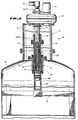
- Figure 1 is a perspective, partially cutaway view of a nutsche filter incorporating the invention.
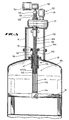
- Figure 2 is a cross sectional view of the filter of the preferred embodiment with the impeller in the down position.
- Figure 3 is an enlarged partial cross sectional view of a portion of the filter emphasizing the relationship between the drive shaft and the impeller shaft.
- Figure 4 is a cross sectional view along line 4-4 in Figure 3.
- Figure 5 is a partial, cross sectional view of the filter having a screw actuated drive unit.
- a nutsche process filter 10 of the present invention is shown in Fig. 1.
- Filter 10 includes a drive unit 12, housing 14, vessel 16 and legs 18.
- a preferred embodiment incorporating a hydraulic drive is shown in Figures 2-4.
- a second embodiment of the invention incorporating a screw-actuated impeller lift mechanism is shown in Figure 5.
- Drive unit 12 is disposed partially on top of and inside housing 14, and partially inside the vessel 16.
- Drive unit 12 comprises a motor 20, speed reducer 22, shaft 24, guide assembly 26, drive shaft assembly 28 and impeller 30.
- Motor 20 and speed reducer 22 are disposed on top of the housing 14.
- motor 20 is hydraulic; however, electrical, mechanical or other drive means are also acceptable.
- Speed reducer 22 is rotatively coupled to motor 20.
- Drive shaft 24 is rotatively coupled to speed reducer 22 and is in fluid communication with a separate hydraulic power source 25 (See Figure 1).
- Drive shaft 24 includes a top 32, a bore 34 having an upper stage 36 and a lower stage 38, at least one spline 40, at least one passageway 42, a shoulder 44 and threads 46.
- a tube 48 is disposed inside the two-stage bore where tube 48 isolates upper stage 36 from the lower stage 38.
- a rotary union or coupling 50 is disposed on top 32 of shaft 24 in fluid communication with bore 34.
- Guide assembly 26 is disposed on top and inside of vessel 16 and adapted to receive drive shaft assembly 28.
- Guide assembly 26 includes ring 52 and flange 54.
- Ring 52 is disposed in an opening 55 in the top of vessel 16.
- Flange 54 is disposed inside and on top of ring 52.
- Flange 54 includes a shoulder 56 and passageway 58 and is secured to ring 52.
- Impeller shaft assembly 28 is slideably disposed around drive shaft 24 and through guide assembly 26.
- Impeller shaft assembly 28 includes a top flange 60, sleeve 62 and impeller shaft 64.
- Top flange 60 includes neck 66 and shoulder 68.
- Top flange 60 is disposed around shaft 24 where neck 66 is disposed next to shaft 24 in sliding relation.
- Bushing 70 is disposed between the remaining portion of top flange 60 and shaft 24.
- Sleeve 62 is disposed around shaft 24 beneath top flange 60.
- Sleeve 62 includes shoulder 72 and internal splines 74.
- Internal splines 74 of sleeve 62 slideably engage splines 40 of drive shaft 24.
- Impeller shaft 64 is disposed around sleeve 62 and through guide assembly 26. A shoulder 78 is disposed around the top of impeller shaft 64. The impeller 30 is connected to the bottom of impeller shaft 64. The bottom of impeller shaft 64 is sealed.
- Shoulder 72 of sleeve 62 is disposed between shoulder 68 of top flange 60 and shoulder 78 of impeller shaft 64. Those three components are connected to each other by a fastening means 82, preferably a nut and bolt arrangement.
- a first packing assembly 84 is disposed between guide assembly 26 and impeller shaft 64.
- Packing assembly 84 includes a compression flange 86, packing 88, bushing 89 bottom flange 90 and sealing ring 92.
- Compression flange 86 is connected to the guide flange 54 by fastening means 94, preferably bolts.
- the sealing ring 92 and bottom flange 90 are connected to the guide flange 54 by a fastening means 96, preferably bolts.
- Packing 88 is disposed between the compression flange 86 and bottom flange 90.
- packing 88 includes a lantern ring 97 for fluid and pressure relief.
- a second packing assembly 98 is disposed between impeller shaft 64 and the bottom portion of drive shaft 24.
- the packing assembly 98 includes upper locating ring 100, spacing ring 101, packing 102, bushing 103, lower locating ring 104 and nut 106.
- Upper locating ring 100 is disposed against a shoulder 44 in drive shaft 24.
- Packing 102 is disposed between upper locating ring 100 and lower locating ring 104.
- Nut 106 is threaded on drive shaft 24 to hold the packing assembly 98 in place.
- Drive unit 12 operates as follows. Motor 20 is actuated and engages speed reducer 22 to impart rotational motion into drive shaft 24. As shaft 24 rotates, fluid may be pumped by a power source 25 through tube 48 into a space 110 between second packing assembly 98 and the bottom of impeller shaft 64. As space 110 is filled, the fluid pushes on the bottom of impeller shaft 64. That forces the impeller shaft 64 to slide on drive shaft 24, lowering the impeller 30.
- Impeller 30 When processing is complete, the impeller 30 is raised. Impeller 30 is raised by feeding hydraulic fluid outside tube 48 and through upper stage 36 of bore 34. The fluid travels through passageway 42 into the space 112 between packing assembly 98 and an O-ring or other suitable seal in top flange 60, forcing the impeller shaft 64 to rise on drive shaft 24.
- FIG. 5 A second embodiment of the inventive drive unit 12 is shown in Figure 5.
- the screw actuated drive unit 12 comprises a two piece shaft 120, motor assembly 122, a guide assembly 26, a threaded impeller drive shaft assembly 124 and the impeller 30.
- This embodiment is generally similar to the embodiment of Figs. 1-4.
- the principal differences include the two piece shaft 120, motor assembly 122 and drive shaft assembly 124.
- the remainder of the drive unit 12 is substantially the same as the preferred first embodiment of Figs. 1-4.
- Two piece drive shaft assembly 120 includes drive shaft 126 and threaded shaft 128.
- Drive shaft 126 includes bore 130 and external splines 131.
- Threaded shaft 128 is rotateably disposed in bore 130 of drive shaft shaft 126, where shafts 126 and 128 may rotate independently of one another.
- Threaded shaft 128 includes a collar 132 and threaded section 134.
- Motor assembly 122 is disposed on top of housing 14 and includes the motor 20 and speed reducer 22, a threaded shaft motor 136, gear reducer 138 and clutch 140. Threaded shaft motor 136 is rotateably coupled with gear reducer 138 which is rotateably coupled to clutch 140.
- Drive shaft 126 is rotateably coupled with speed reducer 22 in the same fashion as drive shaft 24.
- Threaded shaft 128 is rotateably coupled to, and is held in a fixed vertical position by clutch 140.
- Impeller shaft assembly 124 is slideably disposed around drive shaft 126 and through guide assembly 26.
- Impeller shaft assembly 124 includes sleeve 62, impeller shaft 64, drive shaft assembly 120, and a stroke tube 142.
- Sleeve 62 is disposed around drive shaft 126.
- Sleeve 62 includes a shoulder 72 and internal splines 74.
- Internal splines 74 slideably engage splines 131 of drive shaft 126.
- Impeller shaft 64 is disposed around sleeve 62 and through guide assembly 26. Impeller shaft 64 includes shoulder 78 and base plate 144. Base plate 144 seals the bottom of impeller shaft 64. The bottom of shoulder 72 of sleeve 62 is connected to the top of shoulder 78 of impeller shaft 64 by suitable fastening means 146.
- a bushing 148 is connected to the bottom of drive shaft 126 and is adapted to receive threaded stroke tube 142.
- Threaded stroke tube 142 is connected at one end to the base plate 144, and the other end extends through bushing 148. Stroke tube 142 includes internal threads adapted to receive the threaded portion 134 of threaded shaft 128.
- This embodiment operates in the same fashion as the first preferred embodiment but for the manner of vertical displacement of the impeller shaft.
- the vertical displacement of the impeller shaft in this embodiment operates as follows.
- the threaded shaft motor 136 is actuated.
- Clutch 140 engages and rotates threaded shaft 128. As the shaft 128 rotates, it unthreads the stroke tube 142 causing the impeller shaft 64 to lower. Clutch 140 is disengaged or adjusted to slip when the impeller 30 reaches the desired depth in the filter.
- the impeller 30 is raised by first reversing the threaded shaft motor 136. Clutch 140 then engages the threaded shaft 128 which now threads into the stroke tube 142. The clutch 140 is disengaged or adjusted to slip when the impeller 30 reaches its desired height.
Landscapes
- Chemical & Material Sciences (AREA)
- Chemical Kinetics & Catalysis (AREA)
- Structures Of Non-Positive Displacement Pumps (AREA)
- Electrical Discharge Machining, Electrochemical Machining, And Combined Machining (AREA)
- Non-Portable Lighting Devices Or Systems Thereof (AREA)
- Paper (AREA)
- Filtration Of Liquid (AREA)
- Centrifugal Separators (AREA)
- Earth Drilling (AREA)
Abstract
Description
Claims (18)
- "A nutsche filter comprising:(a) an enclosed filter vessel (16) including a laterally disposed filter plate, a drain in the bottom and an opening (55) in the top;(b) an impeller (30) and a tubular drive and impeller shaft assembly (28), said impeller (30) being laterally disposed within the filter vessel (16) above said filter plate, the tubular impeller shaft (64) attached at its lower end to the impeller (30) and extending up through the opening (55) in the vessel (16) in rotatable and axially slidable, sealed relation,(c) a hollow drive shaft (24) mounted within the tubular impeller shaft (64) in corotatable and axially slidable relation;(d) a first power drive transmission (20,22;122) coupled to the hollow drive shaft (24) operable to rotate said hollow drive shaft (24) about its longitudinal axis;(e) a drive housing (14) vertically mounted around the opening (55),
characterised in that(f) the drive housing (14) and hollow drive shaft (24) are in vertically fixed positions,(g) there is a reversible second power drive transmission (25,50;136,138,140) capable of being coupled to the impeller shaft through the hollow drive shaft (24) and operable to telescope the impeller shaft (64) axially over the hollow drive shaft (24),(h) the upper end of the tubular impeller shaft is enclosed within the drive housing (14). - Nutsche filter according to claim 1, wherein the second power transmission comprises a hydraulic powered drive (12, 25, 50).
- Nutsche filter according to claim 2, wherein a reversible hydraulic fluid circuit supplied by a hydraulic power source (25) is provided in the hollow drive shaft (24) which conveys hydraulic fluid up ad down this drive shaft (24) to effect vertical movement of the impeller shaft (64).
- Nutsche filter according to claim 3, wherein the hydraulic fluid up and down flow occurs in two separate flow conduits (36, 42; 38) established in the drive shaft (24) by means of a bore (34), these two flow conduits being separated by a tube (48) within the drive shaft (24).
- Nutsche filter according to claim 4, wherein said tube (48) is adapted to apply hydraulic power via a first conduit (38) to the impeller shaft (64) to move the impeller shaft (64) within a guide assembly (26) axially in a first direction, and a second conduit (36, 42, 112) is adapted to apply hydraulic power to the impeller shaft (64) to move the impeller shaft (64) axially in a direction opposite to the first direction.
- Nutsche filter according to claim 4, in which the bore (34) of the drive shaft (24) defines an upper stage (36) of relatively large diameter ad a lower stage (38) of relatively small diameter positioned below the second conduit (42), and the tube (48) extending down the two stages and sized to fit closely within said lower stage (38) and separating the two stages (36, 38) of the bore (34), a radial passageway (42) of the drive shaft (24) being in fluid communication with the upper stage (36) of the bore (34) and with an annular space (112) which defines the lower end of a sleeve (62) vertically moveable with the impeller shaft (64).
- Nutsche filter according to claim 1, further comprising:a motor (20) rotatably coupled to the drive shaft (24);a sleeve (62) slidably and co-rotatably disposed on the drive shaft (24); andas means for controllably moving the sleeve (62) together with the impeller shaft (64) along the drive shaft (24) the hydraulically actuated system (25, 48, 36, 38, 42, 58, 112).
- Nutsche filter according to claim 7, further including a speed reducer (22) disposed between the motor (20) and the drive shaft (24) and rotatively coupled to the motor (20) and the drive shaft (24).
- Nutsche filter according to claim 7, which further comprises a spline connection (40, 74) between the drive shaft (24) and the sleeve (62).
- Nutsche filter according to claim 8, wherein the motor (20) and the speed reducer (22) are hydraulically actuated and the splined sleeve (62) engages the splined drive shaft (24) in co-rotatable and axially slidable relation.
- Nutsche filter according to claim 1, wherein the drive shaft (24) comprises:(a) at least one longitudinal external spline (40);(b) as fluid conduit a two stage bore (34) in which an upper stage (36) is greater in diameter than a lower stage (38);(c) at least one passageway (42) penetrating the wall of drive shaft (24);(d) a shoulder (44) resting on a locating ring (10) fixed to the guide assembly (26) which is attached to the vessel (16); and(e) threads disposed at the bottom of drive shaft (24) for receiving a locating ring (104) and a nut (106).
- Nutsche filter according to claim 1, comprising:a guide flange (54) being connected to the vessel (16) and disposed around the impeller shaft (64) in sliding and rotatable relation, said guide flange (54) being adapted to close an opening in the nutsche filter for the impeller shaft (64);(a) a top flange (78) disposed around the drive shaft (24) on axially slidable, sealed relation;(b) a sleeve (62) disposed around the drive shaft (24) attached to the top flange (60) at its upper end and having at least one internal spline (74) at the other end engageable with the splined drive shaft (24); and(c) the hollow impeller shaft (64) disposed around the sleeve (62) having a top end attachable with the sleeve to the upper flange (60);
a packing assembly (98) being disposed around the drive shaft (24) below said passageway (42) and adapted to seal the annular space between the drive shaft (24) and the impeller shaft (64) below the sleeve (62);
a packing (102) being disposed between the drive shaft (24) below its shoulder (44) and the impeller shaft (64); and
a nut (106) being threaded on threads of the shaft (24) and holding the packing assembly (98) in its place. - Nutsche filter according to claim 1, wherein the second power transmission comprises a mechanical power transmission.
- Nutsche filter according to claim 13, wherein a screw actuated drive unit (136, 140) engages a two piece shaft (120) for vertical displacement of the impeller shaft (64).
- Nutsche filter according to claim 14, wherein the two piece shaft (120) includes a drive shaft (126) and a threaded shaft (128) being rotatably disposed in a bore of the drive shaft (126), the shafts (126) and (128) being capable to rotate independently of one another.
- Nutsche filter according to claim 15, wherein the threaded shaft (128) includes a collar (132) and a threaded section (134), a bushing (148) being connected to the bottom of the drive shaft 8126) and adapted to receive a threaded stroke tube (142).
- Nutsche filter according to claim 16, wherein the threaded stroke tube 8142) is connected at its lower end to a base plate (144) sealing the bottom of the impeller shaft (64), its other end extending through the bushing (148) including internal threads adapted to receive the threaded portion (134) of the threaded shaft (128), the stroke tube (142) being capable to screw axially within said annular bore (120) for axially lifting or lowering the impeller shaft (64).
- Nutsche filter according to claim 15, whereinthe bushing (148) is mounted around the lower end of the drive shaft (24) below the lower end of the sleeve (62) and adapted to fit within the impeller shaft (64) in a sliding relation; and the threaded shaft (128) is disposed within the hollow drive shaft (126) in rotatable relation to define the annular space within said drive shaft (126).
Applications Claiming Priority (3)
| Application Number | Priority Date | Filing Date | Title |
|---|---|---|---|
| US286959 | 1981-07-27 | ||
| US28695988A | 1988-12-20 | 1988-12-20 | |
| PCT/US1989/005540 WO1990006798A1 (en) | 1988-12-20 | 1989-12-06 | Nutsche process filter drive unit |
Publications (2)
| Publication Number | Publication Date |
|---|---|
| EP0402441A1 EP0402441A1 (en) | 1990-12-19 |
| EP0402441B1 true EP0402441B1 (en) | 1998-10-07 |
Family
ID=23100875
Family Applications (1)
| Application Number | Title | Priority Date | Filing Date |
|---|---|---|---|
| EP90900651A Expired - Lifetime EP0402441B1 (en) | 1988-12-20 | 1989-12-06 | Nutsche process filter drive unit |
Country Status (6)
| Country | Link |
|---|---|
| EP (1) | EP0402441B1 (en) |
| JP (1) | JPH0824809B2 (en) |
| AT (1) | ATE171881T1 (en) |
| AU (1) | AU4807590A (en) |
| DE (1) | DE68928827T2 (en) |
| WO (1) | WO1990006798A1 (en) |
Families Citing this family (3)
| Publication number | Priority date | Publication date | Assignee | Title |
|---|---|---|---|---|
| ATE380060T1 (en) * | 2004-05-23 | 2007-12-15 | Rosenmund Vta Ag | METHOD AND DEVICE FOR REMOVAL OF RESIDUAL PRODUCTS |
| CA2738043C (en) * | 2008-09-30 | 2014-08-05 | Japan Oil, Gas And Metals National Corporation | Catalyst separation system |
| CN112875828B (en) * | 2021-02-26 | 2023-02-17 | 生态环境部南京环境科学研究所 | Organic wastewater and sewage treatment equipment |
Family Cites Families (10)
| Publication number | Priority date | Publication date | Assignee | Title |
|---|---|---|---|---|
| US4081381A (en) * | 1975-09-24 | 1978-03-28 | Rosenmund Ag | Filtering apparatus |
| JPS5752847A (en) * | 1980-09-13 | 1982-03-29 | Matsushita Electric Ind Co Ltd | Sensor element |
| JPS5835726B2 (en) * | 1980-09-19 | 1983-08-04 | 日本染色機械株式会社 | filtration device |
| JPS5835726A (en) * | 1981-08-21 | 1983-03-02 | Hitachi Ltd | Magnetic disc |
| JPS59109215A (en) * | 1982-12-13 | 1984-06-23 | Sumitomo Chem Co Ltd | Nutsche type filter |
| JPS60149768A (en) * | 1984-01-11 | 1985-08-07 | Hitachi Ltd | Metallized film having high adhesion |
| JPS621416A (en) * | 1985-06-24 | 1987-01-07 | Mitsubishi Kakoki Kaisha Ltd | Automatic nutsche type filter |
| US4620913A (en) * | 1985-11-15 | 1986-11-04 | Multi-Arc Vacuum Systems, Inc. | Electric arc vapor deposition method and apparatus |
| JPS62224670A (en) * | 1986-03-26 | 1987-10-02 | Fuji Photo Film Co Ltd | Ionization vapor deposition device |
| JPS63116712A (en) * | 1986-10-31 | 1988-05-21 | Nippon Shiyuumatsuhaa Kk | Separating and drying apparatus |
-
1989
- 1989-12-06 EP EP90900651A patent/EP0402441B1/en not_active Expired - Lifetime
- 1989-12-06 JP JP2501397A patent/JPH0824809B2/en not_active Expired - Lifetime
- 1989-12-06 WO PCT/US1989/005540 patent/WO1990006798A1/en active IP Right Grant
- 1989-12-06 AU AU48075/90A patent/AU4807590A/en not_active Abandoned
- 1989-12-06 AT AT90900651T patent/ATE171881T1/en active
- 1989-12-06 DE DE68928827T patent/DE68928827T2/en not_active Expired - Fee Related
Also Published As
| Publication number | Publication date |
|---|---|
| DE68928827D1 (en) | 1998-11-12 |
| DE68928827T2 (en) | 1999-06-17 |
| AU4807590A (en) | 1990-07-10 |
| ATE171881T1 (en) | 1998-10-15 |
| WO1990006798A1 (en) | 1990-06-28 |
| JPH0824809B2 (en) | 1996-03-13 |
| EP0402441A1 (en) | 1990-12-19 |
| JPH03502781A (en) | 1991-06-27 |
Similar Documents
| Publication | Publication Date | Title |
|---|---|---|
| US5139667A (en) | Nutsche process filter drive unit | |
| EP2105576B1 (en) | Tubular filling system | |
| WO1988008069A3 (en) | Apparatus for use in drilling | |
| US20040262015A1 (en) | Convertible jack | |
| CA2108838C (en) | Apparatus for rotating a tubing string of a pumping wellhead | |
| EP0402441B1 (en) | Nutsche process filter drive unit | |
| US2810550A (en) | Earth boring machine | |
| US2803434A (en) | Rotary well drilling machine | |
| US5269923A (en) | Agitator suction filter | |
| US2588115A (en) | Sedimentation device | |
| US4214445A (en) | Hydraulic circuitry for raise drill apparatus | |
| CA2393752A1 (en) | Combined power tong having integrated mud suction and thread doping apparatus | |
| US4315552A (en) | Raise drill apparatus | |
| GB1603608A (en) | Drive unit for drill rig | |
| CA1131052A (en) | Chuck and wrench assembly for raise drill apparatus | |
| RU111876U1 (en) | MOBILE DRILLING AND DRILLING UNIT | |
| US1956200A (en) | Rotary drill and clean out machine | |
| RU2237790C1 (en) | Upper power drive for drilling device | |
| JPH05246533A (en) | Elevation type turn table | |
| CN220561031U (en) | Milling cutter drill bit auxiliary cleaning device | |
| US2478233A (en) | Posthole digger | |
| CN117536618B (en) | Hydraulic auxiliary splitting equipment for rock breaking | |
| US2006128A (en) | Rotary drill | |
| RU96117901A (en) | Borehole Pumping Unit | |
| CN210859764U (en) | Well drilling machine gearbox and power device |
Legal Events
| Date | Code | Title | Description |
|---|---|---|---|
| PUAI | Public reference made under article 153(3) epc to a published international application that has entered the european phase |
Free format text: ORIGINAL CODE: 0009012 |
|
| 17P | Request for examination filed |
Effective date: 19900820 |
|
| AK | Designated contracting states |
Kind code of ref document: A1 Designated state(s): AT BE CH DE FR GB IT LI LU NL SE |
|
| 17Q | First examination report despatched |
Effective date: 19930702 |
|
| GRAG | Despatch of communication of intention to grant |
Free format text: ORIGINAL CODE: EPIDOS AGRA |
|
| GRAG | Despatch of communication of intention to grant |
Free format text: ORIGINAL CODE: EPIDOS AGRA |
|
| GRAH | Despatch of communication of intention to grant a patent |
Free format text: ORIGINAL CODE: EPIDOS IGRA |
|
| GRAH | Despatch of communication of intention to grant a patent |
Free format text: ORIGINAL CODE: EPIDOS IGRA |
|
| GRAA | (expected) grant |
Free format text: ORIGINAL CODE: 0009210 |
|
| AK | Designated contracting states |
Kind code of ref document: B1 Designated state(s): AT BE CH DE FR GB IT LI LU NL SE |
|
| PG25 | Lapsed in a contracting state [announced via postgrant information from national office to epo] |
Ref country code: BE Free format text: LAPSE BECAUSE OF FAILURE TO SUBMIT A TRANSLATION OF THE DESCRIPTION OR TO PAY THE FEE WITHIN THE PRESCRIBED TIME-LIMIT Effective date: 19981007 Ref country code: AT Free format text: LAPSE BECAUSE OF FAILURE TO SUBMIT A TRANSLATION OF THE DESCRIPTION OR TO PAY THE FEE WITHIN THE PRESCRIBED TIME-LIMIT Effective date: 19981007 |
|
| REF | Corresponds to: |
Ref document number: 171881 Country of ref document: AT Date of ref document: 19981015 Kind code of ref document: T |
|
| REG | Reference to a national code |
Ref country code: CH Ref legal event code: EP |
|
| REF | Corresponds to: |
Ref document number: 68928827 Country of ref document: DE Date of ref document: 19981112 |
|
| PG25 | Lapsed in a contracting state [announced via postgrant information from national office to epo] |
Ref country code: LU Free format text: LAPSE BECAUSE OF NON-PAYMENT OF DUE FEES Effective date: 19981206 |
|
| PG25 | Lapsed in a contracting state [announced via postgrant information from national office to epo] |
Ref country code: SE Free format text: LAPSE BECAUSE OF FAILURE TO SUBMIT A TRANSLATION OF THE DESCRIPTION OR TO PAY THE FEE WITHIN THE PRESCRIBED TIME-LIMIT Effective date: 19990107 |
|
| ET | Fr: translation filed | ||
| REG | Reference to a national code |
Ref country code: CH Ref legal event code: NV Representative=s name: HEPP, WENGER & RYFFEL AG |
|
| PLBE | No opposition filed within time limit |
Free format text: ORIGINAL CODE: 0009261 |
|
| STAA | Information on the status of an ep patent application or granted ep patent |
Free format text: STATUS: NO OPPOSITION FILED WITHIN TIME LIMIT |
|
| 26N | No opposition filed | ||
| PGFP | Annual fee paid to national office [announced via postgrant information from national office to epo] |
Ref country code: GB Payment date: 19991201 Year of fee payment: 11 |
|
| PGFP | Annual fee paid to national office [announced via postgrant information from national office to epo] |
Ref country code: FR Payment date: 19991208 Year of fee payment: 11 |
|
| PGFP | Annual fee paid to national office [announced via postgrant information from national office to epo] |
Ref country code: CH Payment date: 19991210 Year of fee payment: 11 |
|
| PGFP | Annual fee paid to national office [announced via postgrant information from national office to epo] |
Ref country code: NL Payment date: 19991228 Year of fee payment: 11 |
|
| PG25 | Lapsed in a contracting state [announced via postgrant information from national office to epo] |
Ref country code: GB Free format text: LAPSE BECAUSE OF NON-PAYMENT OF DUE FEES Effective date: 20001206 |
|
| PG25 | Lapsed in a contracting state [announced via postgrant information from national office to epo] |
Ref country code: LI Free format text: LAPSE BECAUSE OF NON-PAYMENT OF DUE FEES Effective date: 20001231 Ref country code: CH Free format text: LAPSE BECAUSE OF NON-PAYMENT OF DUE FEES Effective date: 20001231 |
|
| PG25 | Lapsed in a contracting state [announced via postgrant information from national office to epo] |
Ref country code: NL Free format text: LAPSE BECAUSE OF NON-PAYMENT OF DUE FEES Effective date: 20010701 |
|
| GBPC | Gb: european patent ceased through non-payment of renewal fee |
Effective date: 20001206 |
|
| REG | Reference to a national code |
Ref country code: CH Ref legal event code: PL |
|
| PG25 | Lapsed in a contracting state [announced via postgrant information from national office to epo] |
Ref country code: FR Free format text: LAPSE BECAUSE OF NON-PAYMENT OF DUE FEES Effective date: 20010831 |
|
| NLV4 | Nl: lapsed or anulled due to non-payment of the annual fee |
Effective date: 20010701 |
|
| REG | Reference to a national code |
Ref country code: FR Ref legal event code: ST |
|
| PGFP | Annual fee paid to national office [announced via postgrant information from national office to epo] |
Ref country code: DE Payment date: 20020628 Year of fee payment: 13 |
|
| PG25 | Lapsed in a contracting state [announced via postgrant information from national office to epo] |
Ref country code: DE Free format text: LAPSE BECAUSE OF NON-PAYMENT OF DUE FEES Effective date: 20030701 |
|
| PG25 | Lapsed in a contracting state [announced via postgrant information from national office to epo] |
Ref country code: IT Free format text: LAPSE BECAUSE OF NON-PAYMENT OF DUE FEES Effective date: 20051206 |