EP0402325A2 - Vorrichtung zum Herstellen von Rollen aus bahnförmigem Material auf einer Hülse - Google Patents
Vorrichtung zum Herstellen von Rollen aus bahnförmigem Material auf einer Hülse Download PDFInfo
- Publication number
- EP0402325A2 EP0402325A2 EP90830237A EP90830237A EP0402325A2 EP 0402325 A2 EP0402325 A2 EP 0402325A2 EP 90830237 A EP90830237 A EP 90830237A EP 90830237 A EP90830237 A EP 90830237A EP 0402325 A2 EP0402325 A2 EP 0402325A2
- Authority
- EP
- European Patent Office
- Prior art keywords
- core
- nip
- roll
- winding roller
- roller
- Prior art date
- Legal status (The legal status is an assumption and is not a legal conclusion. Google has not performed a legal analysis and makes no representation as to the accuracy of the status listed.)
- Withdrawn
Links
Images

Classifications
-
- B—PERFORMING OPERATIONS; TRANSPORTING
- B65—CONVEYING; PACKING; STORING; HANDLING THIN OR FILAMENTARY MATERIAL
- B65H—HANDLING THIN OR FILAMENTARY MATERIAL, e.g. SHEETS, WEBS, CABLES
- B65H37/00—Article or web delivery apparatus incorporating devices for performing specified auxiliary operations
- B65H37/04—Article or web delivery apparatus incorporating devices for performing specified auxiliary operations for securing together articles or webs, e.g. by adhesive, stitching or stapling
-
- B—PERFORMING OPERATIONS; TRANSPORTING
- B65—CONVEYING; PACKING; STORING; HANDLING THIN OR FILAMENTARY MATERIAL
- B65H—HANDLING THIN OR FILAMENTARY MATERIAL, e.g. SHEETS, WEBS, CABLES
- B65H19/00—Changing the web roll
- B65H19/22—Changing the web roll in winding mechanisms or in connection with winding operations
- B65H19/28—Attaching the leading end of the web to the replacement web-roll core or spindle
- B65H19/283—Attaching the leading end of the web to the replacement web-roll core or spindle by applying adhesive to the core
-
- B—PERFORMING OPERATIONS; TRANSPORTING
- B65—CONVEYING; PACKING; STORING; HANDLING THIN OR FILAMENTARY MATERIAL
- B65H—HANDLING THIN OR FILAMENTARY MATERIAL, e.g. SHEETS, WEBS, CABLES
- B65H19/00—Changing the web roll
- B65H19/22—Changing the web roll in winding mechanisms or in connection with winding operations
- B65H19/30—Lifting, transporting, or removing the web roll; Inserting core
-
- B—PERFORMING OPERATIONS; TRANSPORTING
- B65—CONVEYING; PACKING; STORING; HANDLING THIN OR FILAMENTARY MATERIAL
- B65H—HANDLING THIN OR FILAMENTARY MATERIAL, e.g. SHEETS, WEBS, CABLES
- B65H2301/00—Handling processes for sheets or webs
- B65H2301/40—Type of handling process
- B65H2301/41—Winding, unwinding
- B65H2301/417—Handling or changing web rolls
- B65H2301/4171—Handling web roll
- B65H2301/4173—Handling web roll by central portion, e.g. gripping central portion
-
- B—PERFORMING OPERATIONS; TRANSPORTING
- B65—CONVEYING; PACKING; STORING; HANDLING THIN OR FILAMENTARY MATERIAL
- B65H—HANDLING THIN OR FILAMENTARY MATERIAL, e.g. SHEETS, WEBS, CABLES
- B65H2301/00—Handling processes for sheets or webs
- B65H2301/40—Type of handling process
- B65H2301/41—Winding, unwinding
- B65H2301/417—Handling or changing web rolls
- B65H2301/418—Changing web roll
- B65H2301/4181—Core or mandrel supply
- B65H2301/41812—Core or mandrel supply by conveyor belt or chain running in closed loop
-
- B—PERFORMING OPERATIONS; TRANSPORTING
- B65—CONVEYING; PACKING; STORING; HANDLING THIN OR FILAMENTARY MATERIAL
- B65H—HANDLING THIN OR FILAMENTARY MATERIAL, e.g. SHEETS, WEBS, CABLES
- B65H2301/00—Handling processes for sheets or webs
- B65H2301/40—Type of handling process
- B65H2301/41—Winding, unwinding
- B65H2301/417—Handling or changing web rolls
- B65H2301/418—Changing web roll
- B65H2301/4181—Core or mandrel supply
- B65H2301/41816—Core or mandrel supply by core magazine within winding machine, i.e. horizontal or inclined ramp holding cores
-
- B—PERFORMING OPERATIONS; TRANSPORTING
- B65—CONVEYING; PACKING; STORING; HANDLING THIN OR FILAMENTARY MATERIAL
- B65H—HANDLING THIN OR FILAMENTARY MATERIAL, e.g. SHEETS, WEBS, CABLES
- B65H2408/00—Specific machines
- B65H2408/20—Specific machines for handling web(s)
- B65H2408/23—Winding machines
- B65H2408/235—Cradles
Definitions
- the invention is an improvement on prior means for the formation of rolls or logs by winding a web of paper or similar material on a core.
- Prior art shows a first rotary winding roller along which the web material is driven; a second rotary winding roller forming a nip with said first winding roller to receive a fed core; means for inserting a core into said nip; and a movable roller to control the diameter of the roll or log during formation between said three rollers.
- the prior apparatus also provides for cyclically varying the surface speed of the second winding roller and of the diameter control roller in order to achieve, during each insertion of a new core, the slackening of the web and thus the wedging of a double thickness of web between the just-inserted core and the second winding roller.
- This may include pneumatic means. This causes the paper to start the winding on the newly- inserted core and to tear between the just-finished roll and the newly-inserted core.
- the present invention simplifies the apparatus and makes the start of the winding of paper on the core more regular.
- the second roller be combined with means for reducing the speed thereof during the phase of inserting a core into said nip; that means be provided to wet with glue the cores to be inserted in said nip; and that a take-off surface extends from a zone of said second winding roller which is adjacent to the exit of said nip.
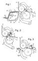
- numeral 1 indicates a first upper winding roller, around which there is continuously driven the web N, which is transversally perforated at predetermined distances according to the size of the sheets that must be detached from the finished roll.
- Numeral 3 indicates a second, lower winding roller which, together with roller 1, defines space (i.e., a nip 5) for the insertion of a tubular core made of cardboard or similar material, around which the roll is to be formed.
- Numeral 7 indicates a diameter control movable roller which cooperates with rollers 1 and 3 to form a roll R of paper material N which is fed without stopping.
- Numeral 9 indicates a take-off surface which is a part of a unit 10 that may be either fixed or adjusted in position. The surface 9 has a front edge 9a, substantially adjacent and almost touching the lower winding roller 3 at the zone of formation of the roll R between the three rollers 1, 3 and 7. The surface 9 may be slightly inclined to allow the spontaneous rolling removal of the roll in the direction of arrow f9.
- Numeral 12 generally indicates a pusher for the insertion of a core A1 into the nip 5 formed by rollers 1 and 3.
- the pusher 12 may be formed by arms pivoted at 14 to the fixed structure and having an end 12a to push the core A1 into the nip 5.
- Numeral 16 indicates an assembly for successively feeding cores to the position A1, from which they are moved by the pusher 12 to the nip 5.
- This assembly 16 may comprise a flexible conveyor 18 having a plurality of seats for the cores A fed from a chute-like supply reservoir AO.
- the cores have adhesive applied thereto by a distributor 20 which may comprise a basin 22 and an assembly of distribution cylinders and counter-rollers, generally indicated by 24, to transfer a required amount of adhesive onto their surface until they contact a core in transit, thereby determining a glueing region on said core.
- the glueing region may consist of either longitudinal segments parallel to the core axis or annular bands of adhesive spaced from each other.
- the adhesive is such as to ensure the anchorage of the leading edge of the web material N that must be wound on the core.
- the winding roller 1 rotates with a peripheral speed corresponding to the feeding speed of the paper web N and, therefore, with constant speed.
- the diameter control roller 7 also rotates uniformly at the same circumferential speed of roller 1.
- the winding roller S rotates at the same peripheral speed as rollers 1 and 7, for the most part of the winding cycle.
- roller 3 undergoes a short slowing down phase for the purposes indicated below.
- the pusher 12 moves the core A1 in the direction of arrow f12 into the nip 5 where it comes in contact with rollers 1 and 3.
- the winding roller 3 is made to slow down slightly which causes the roll R to move in the direction of arrow f9 until it strikes the front edge 9a of surface 9.
- the slowing down of roller 3 also causes a slight advancement of core A1 into the nip 5.
- a reversing of the paper material is thus caused in a direction opposite to that of the advancement of said material during the winding thereof on the roll R.
- the web N is torn in the region NO. If the web is perforated (for the formation of a log or roll made up of a plurality of sheets to be detached along the perforation lines), the web tears along the perforation in region NO. It is preferred that the web in region NO is determined by a synchronization between the core assembly 16 and the lines of transversal perforations formed in the paper material N.
- the roll R With the tearing of web N at the region NO, the roll R is separated from the incoming web material N and is moved away in the direction of arrow f9 by the rolling effect caused by the rotation of the diameter control roller 7, and made easier by the inclined surface 9.
- the leading edge of web N is glued to the core A1 and pressed thereon by the contact of the core between roller 1 and with roller 3 so that, during the rotation of the core, the web end fold, which has wedged itself between the core 1 and the roller 3, is made to follow the rotating core. In this way the winding of the paper material begins immediately on the newly-inserted core A1.
- the completed roll R is moved away (see Fig. 3) and the diameter control roller 7 is lowered towards the nip 5 to come in contact with the new roll that has just begun to be formed.
- the new roll moves out of the nip 5 to come in contact with the diameter control roller 7 owing to the difference in peripheral speed between roller 1 and roller 3.
- the pusher 12 goes back in a direction opposite to arrow f12 to allow the next core to move to position A1 (Fig. 1) from the supply assembly 16.
- This assembly may advance with intermittent motion or continuous motion. The cycle is then repeated in the manner described for the preceding roll.
- Fig. 4 shows in detail another embodiment of the assembly of members already described for the winding and removing of the formed roll.
- the surface 9, and in particular its front edge 9a, facing the nip 5, is advanced towards the nip the moment the formed roll must be stopped by contact with surface 9 and, in particular, with the edge thereof, in order to cause a sudden stop of the roll and the formation of the loop between the roll and the new core inserted into nip 5.
- the surface 9 is part of a unit 30 which is moved forward by a rocker arm 32 pivoted at 34 to the fixed housing frame and connected to the unit 30 through a connecting rod 36.
- the rocker arm 32 is mechanically connected to a tappet 38 which cooperates with a cam 40 mounted on a programming cam shaft 42.
- the system 38, 32, 36 causes a timely and temporary advancement of the edge 99a in the direction of arrow f9 against the just completed roll. This abruptly breaks the roll and causes the formation of the loop as described above.
- the mechanical connection between the rocker arm 32 and the tappet 38 may be of direct type; that is, the two mechanical members may be rigidly connected to one another.
- the angle between the tappet 38 and the rocker arm 32 may be varied and pre-set to meet peculiar working requirements, even during the machine operation.
- the tappet 38 be rigidly connected to a reducer 50 oscillating about the axis 34.
- the rocker arm 32 may be connected to one of two shafts (for example, to the slow shaft of reducer 50), while the other shaft of the reducer 50 is provided with a hand-wheel 52 whose adjustment causes a change of the angle formed by the rocker 32 and tappet 38.
- Fig. 5 shows schematically an assembly similar to the one of Fig. 4, but in which a different device is provided to modify the position of the surface 9.
- the rigid rocker arm 32 is replaced by a rocker arm made up of two portions 132A and 132B, the portion 132A being fastened to the connecting rod 36 and the portion 132B carrying the tappet 38.
- the two portions are articulated on the axis 34, and the portion 132A includes an arm 132C which forms an acute angle with the portion 132B.
- This angle may be adjusted by a screw tension rod 134 having opposite threadings which engage into two movable bushes of portion 132B and of arm 132C.
- the tension rod 134 can be turned by the knob 134A in order to change the above-mentioned angle and thus to change, with respect to tappet 38, the position of the surface 9.
Applications Claiming Priority (2)
| Application Number | Priority Date | Filing Date | Title |
|---|---|---|---|
| IT8909448A IT1234455B (it) | 1989-06-08 | 1989-06-08 | Attrezzatura per formare rotoli cioe' bastoni di materiale nastriforme su di un'anima di avvolgimento |
| IT944889 | 1989-06-08 |
Publications (2)
| Publication Number | Publication Date |
|---|---|
| EP0402325A2 true EP0402325A2 (de) | 1990-12-12 |
| EP0402325A3 EP0402325A3 (de) | 1991-08-07 |
Family
ID=11130292
Family Applications (1)
| Application Number | Title | Priority Date | Filing Date |
|---|---|---|---|
| EP19900830237 Withdrawn EP0402325A3 (de) | 1989-06-08 | 1990-05-25 | Vorrichtung zum Herstellen von Rollen aus bahnförmigem Material auf einer Hülse |
Country Status (7)
| Country | Link |
|---|---|
| EP (1) | EP0402325A3 (de) |
| JP (1) | JPH0326645A (de) |
| KR (1) | KR910019882A (de) |
| BR (1) | BR9002695A (de) |
| CA (1) | CA2018499A1 (de) |
| IL (1) | IL94674A0 (de) |
| IT (1) | IT1234455B (de) |
Cited By (4)
| Publication number | Priority date | Publication date | Assignee | Title |
|---|---|---|---|---|
| EP0498039A1 (de) * | 1991-01-09 | 1992-08-12 | Alberto Consani S.P.A | Verbesserung an Aufwicklern für blattartiges Material |
| EP0620176A2 (de) * | 1993-02-18 | 1994-10-19 | Paper Converting Machine Company | Umwickler mit Kontaktantrieb und Verfahren zu dessen Betrieb |
| WO1994026642A1 (en) * | 1993-05-14 | 1994-11-24 | Fabio Perini S.P.A. | Apparatus and method for applying a glue on a core for the winding of web material |
| EP1657196A2 (de) | 2004-02-10 | 2006-05-17 | Paper Converting Machine Company Italia S.p.A. | Hülsenklebevorrichtung für eine Umwickelmaschine und dazugehöriges Verfahren |
Families Citing this family (3)
| Publication number | Priority date | Publication date | Assignee | Title |
|---|---|---|---|---|
| US7914125B2 (en) | 2006-09-14 | 2011-03-29 | Hewlett-Packard Development Company, L.P. | Fluid ejection device with deflective flexible membrane |
| EP2669224B1 (de) * | 2012-05-29 | 2019-05-22 | Valmet Technologies, Inc. | Verfahren und Vorrichtung in einem Wickler für Bahnen, insbesondere Zuführen neue Wellen in den Wickler |
| CN103879814B (zh) * | 2014-03-19 | 2016-08-24 | 泉州市华讯机械制造有限公司 | 不停机卷纸复卷机 |
Citations (5)
| Publication number | Priority date | Publication date | Assignee | Title |
|---|---|---|---|---|
| DE2335930A1 (de) * | 1972-07-18 | 1974-01-31 | Fabio Perini | Aufwickelvorrichtung mit kontinuierlichem betrieb fuer papierbahnen o. dergl |
| US4327877A (en) * | 1979-09-21 | 1982-05-04 | Fabio Perini | Winding device |
| GB2105688A (en) * | 1981-09-17 | 1983-03-30 | Lucchese Finanz | Snap-separating of web material during transfer of winding onto new core |
| DE3404225A1 (de) * | 1983-04-22 | 1984-10-25 | Paper Converting Machine Co., Green Bay, Wis. | Wickelvorrichtung |
| AT380457B (de) * | 1981-08-26 | 1986-05-26 | Lucchese Finanz | Aufwickelvorrichtung fuer eine werkstoffbahn |
-
1989
- 1989-06-08 IT IT8909448A patent/IT1234455B/it active
-
1990
- 1990-05-25 EP EP19900830237 patent/EP0402325A3/de not_active Withdrawn
- 1990-06-07 CA CA002018499A patent/CA2018499A1/en not_active Abandoned
- 1990-06-07 JP JP2147518A patent/JPH0326645A/ja active Pending
- 1990-06-07 BR BR909002695A patent/BR9002695A/pt unknown
- 1990-06-08 KR KR1019900008387A patent/KR910019882A/ko not_active Application Discontinuation
- 1990-06-08 IL IL94674A patent/IL94674A0/xx unknown
Patent Citations (5)
| Publication number | Priority date | Publication date | Assignee | Title |
|---|---|---|---|---|
| DE2335930A1 (de) * | 1972-07-18 | 1974-01-31 | Fabio Perini | Aufwickelvorrichtung mit kontinuierlichem betrieb fuer papierbahnen o. dergl |
| US4327877A (en) * | 1979-09-21 | 1982-05-04 | Fabio Perini | Winding device |
| AT380457B (de) * | 1981-08-26 | 1986-05-26 | Lucchese Finanz | Aufwickelvorrichtung fuer eine werkstoffbahn |
| GB2105688A (en) * | 1981-09-17 | 1983-03-30 | Lucchese Finanz | Snap-separating of web material during transfer of winding onto new core |
| DE3404225A1 (de) * | 1983-04-22 | 1984-10-25 | Paper Converting Machine Co., Green Bay, Wis. | Wickelvorrichtung |
Cited By (7)
| Publication number | Priority date | Publication date | Assignee | Title |
|---|---|---|---|---|
| EP0498039A1 (de) * | 1991-01-09 | 1992-08-12 | Alberto Consani S.P.A | Verbesserung an Aufwicklern für blattartiges Material |
| EP0620176A2 (de) * | 1993-02-18 | 1994-10-19 | Paper Converting Machine Company | Umwickler mit Kontaktantrieb und Verfahren zu dessen Betrieb |
| EP0620176A3 (de) * | 1993-02-18 | 1995-02-15 | Paper Converting Machine Co | Umwickler mit Kontaktantrieb und Verfahren zu dessen Betrieb. |
| WO1994026642A1 (en) * | 1993-05-14 | 1994-11-24 | Fabio Perini S.P.A. | Apparatus and method for applying a glue on a core for the winding of web material |
| US5653401A (en) * | 1993-05-14 | 1997-08-05 | Fabio Perini S.P.A. | Apparatus and method for applying a glue on a core for the winding of web material |
| EP1657196A2 (de) | 2004-02-10 | 2006-05-17 | Paper Converting Machine Company Italia S.p.A. | Hülsenklebevorrichtung für eine Umwickelmaschine und dazugehöriges Verfahren |
| EP1657196A3 (de) * | 2004-02-10 | 2008-05-14 | Paper Converting Machine Company Italia S.p.A. | Hülsenklebevorrichtung für eine Umwickelmaschine und dazugehöriges Verfahren |
Also Published As
| Publication number | Publication date |
|---|---|
| JPH0326645A (ja) | 1991-02-05 |
| IT1234455B (it) | 1992-05-18 |
| CA2018499A1 (en) | 1990-12-08 |
| IT8909448A0 (it) | 1989-06-08 |
| BR9002695A (pt) | 1991-08-20 |
| IL94674A0 (en) | 1991-04-15 |
| EP0402325A3 (de) | 1991-08-07 |
| KR910019882A (ko) | 1991-12-19 |
Similar Documents
| Publication | Publication Date | Title |
|---|---|---|
| US5137225A (en) | Rewinding machine for the formation of rolls or logs, and winding method | |
| US5031850A (en) | Rewinding machine for the formation of rolls of paper or the like | |
| US7172151B2 (en) | Rewinding machine for producing logs of wound web material and relative method | |
| CA2115496C (en) | Method and machine for producing logs of web material and tearing the web upon completion of the winding of each log | |
| US5368252A (en) | Apparatus and method for winding rolls of web material with severing of web by roll acceleration | |
| US5538199A (en) | Rewinding machine for coreless winding of a log of web material with a surface for supporting the log in the process of winding | |
| US6488226B2 (en) | Web rewinder chop-off and transfer assembly | |
| US4962897A (en) | Web winding machine and method | |
| RU2567202C2 (ru) | Машина для перемотки и способ производства рулонов из рулонного материала | |
| USRE35304E (en) | Apparatus for applying adhesive on tubular cores for rolls of web material and for feeding same cores to a web winding machine | |
| EP0198495A2 (de) | Vorrichtung und Verfahren zum Wickeln von Bahnen | |
| GB2105687A (en) | Separating perforated web on completion of rewinding | |
| EP0507749B1 (de) | Verfahren und Vorrichtung zum Trennen von Materialbahnen | |
| EP0402325A2 (de) | Vorrichtung zum Herstellen von Rollen aus bahnförmigem Material auf einer Hülse | |
| EP2731894B1 (de) | Verfahren und vorrichtung zum brechen eines films mit einer schneideanordnung | |
| EP0331653A2 (de) | Verfahren und Apparat zum Herstellen von Rollen aus perforierten Papierstreifen, eine Rolle, hergestellt auf diese Weise und Spender zum Ausgeben von Bögen von dieser Rolle |
Legal Events
| Date | Code | Title | Description |
|---|---|---|---|
| PUAI | Public reference made under article 153(3) epc to a published international application that has entered the european phase |
Free format text: ORIGINAL CODE: 0009012 |
|
| AK | Designated contracting states |
Kind code of ref document: A2 Designated state(s): AT DE ES GB GR NL |
|
| PUAL | Search report despatched |
Free format text: ORIGINAL CODE: 0009013 |
|
| AK | Designated contracting states |
Kind code of ref document: A3 Designated state(s): AT DE ES GB GR NL |
|
| STAA | Information on the status of an ep patent application or granted ep patent |
Free format text: STATUS: THE APPLICATION IS DEEMED TO BE WITHDRAWN |
|
| 18D | Application deemed to be withdrawn |
Effective date: 19920208 |