EP0401670A2 - Self-priming centrifugal pump - Google Patents
Self-priming centrifugal pump Download PDFInfo
- Publication number
- EP0401670A2 EP0401670A2 EP90110312A EP90110312A EP0401670A2 EP 0401670 A2 EP0401670 A2 EP 0401670A2 EP 90110312 A EP90110312 A EP 90110312A EP 90110312 A EP90110312 A EP 90110312A EP 0401670 A2 EP0401670 A2 EP 0401670A2
- Authority
- EP
- European Patent Office
- Prior art keywords
- impeller
- self
- centrifugal pump
- conveyor
- radial
- Prior art date
- Legal status (The legal status is an assumption and is not a legal conclusion. Google has not performed a legal analysis and makes no representation as to the accuracy of the status listed.)
- Granted
Links
Images
Classifications
-
- F—MECHANICAL ENGINEERING; LIGHTING; HEATING; WEAPONS; BLASTING
- F04—POSITIVE - DISPLACEMENT MACHINES FOR LIQUIDS; PUMPS FOR LIQUIDS OR ELASTIC FLUIDS
- F04D—NON-POSITIVE-DISPLACEMENT PUMPS
- F04D9/00—Priming; Preventing vapour lock
- F04D9/04—Priming; Preventing vapour lock using priming pumps; using booster pumps to prevent vapour-lock
- F04D9/06—Priming; Preventing vapour lock using priming pumps; using booster pumps to prevent vapour-lock of jet type
-
- F—MECHANICAL ENGINEERING; LIGHTING; HEATING; WEAPONS; BLASTING
- F04—POSITIVE - DISPLACEMENT MACHINES FOR LIQUIDS; PUMPS FOR LIQUIDS OR ELASTIC FLUIDS
- F04D—NON-POSITIVE-DISPLACEMENT PUMPS
- F04D29/00—Details, component parts, or accessories
- F04D29/40—Casings; Connections of working fluid
- F04D29/42—Casings; Connections of working fluid for radial or helico-centrifugal pumps
- F04D29/44—Fluid-guiding means, e.g. diffusers
- F04D29/445—Fluid-guiding means, e.g. diffusers especially adapted for liquid pumps
- F04D29/448—Fluid-guiding means, e.g. diffusers especially adapted for liquid pumps bladed diffusers
Definitions
- the present invention relates to a self-priming centrifugal pump particularly of the kind with built-in ejector.
- Jet pumps comprise, inside the pump casing, an ejector which is connected to the intake port on one side and to the inlet of the impeller on the other.
- the flow Q2 on the basis of the known operating principles of ejectors, draws into to the ejector's negative-pressure chamber a flow Q1 which arrives from the intake port. Said flow Q1 mixes in the diffusion duct of the ejector with the flow Q2 and is then conveyed toward the inlet of the impeller to be subsequently recirculated within the case.
- the method of operation of said self-priming pumps is as follows. Initially, the case of the pump must be entirely filled with liquid up to the coupling to the intake port which is located above the axis of the impeller. In this manner the ejector is also completely filled with liquid to be pumped.
- the impeller When the pump is started, the impeller imparts a vorticose motion to the liquid, forming a mixture of air and liquid which is discharged into the upper portion of the case, where the separation of the air can occur at low speeds.
- the separated air partially flows to the delivery port and is partly entrained with the liquid toward the ejection nozzle, where it gradually draws more liquid toward the inlet of the impeller.
- the recirculation of the air/liquid mixture continues until all the air is eliminated, after which the normal operation of the pump can begin.
- priming times correspond to conditions of greater turbulence of the air/liquid mixture which leaves the impeller. Said priming times are also further increased if the flow of the air/liquid mixture is proximate to the delivery port, so as to prevent the separation of air from the mixture and reduce the efficiency of the ejector. Therefore, in order to reduce priming times and increase the overall efficiency of the pump, it is necessary to carefully study the conditions of outflow at the outlet of the impeller and its re-conveyance toward the ejector.
- a self-priming ejector pump in which the flow leaving the impeller, initially guided by an annular diffuser, is subsequently conveyed toward an essentially frustum-shaped interspace and finally discharged through an arc-like slot which faces the intake port of the pump.
- the priming times of said pump are considerably reduced down to 5-6 minutes; however, the efficiency of the pump-ejector assembly in normal running conditions is still not adequate. This is due to the fact that the outflow of the mixture through the arc-like slot is still predominantly turbulent and does not ensure a uniform feeding of the ejection nozzle.
- the aim of the present invention is indeed to eliminate, or at least reduce, the disadvantages described above, by providing a self-priming centrifugal pump with built-in ejector which allows to drastically reduce priming times by means of a simple and economical solution.
- a particular object of the present invention is to provide a conveyance of the fluid which leaves the impeller in substantially laminar conditions, so as to allow an effective separation of the air mixed with the liquid during priming and facilitate its migration toward the delivery port.
- a further object of the present invention is to provide a conveyance device which reduces fluidodynamic losses during the priming period and in normal running conditions.
- Not least object of the invention is to obtain a centrifugal pump which is highly reliable and has reduced maintenance costs, in order to make the assembly rational and advantageous from a merely economical point of view.
- the pump according to the invention comprises a casing or stator case 2 which has an essentially cylindrical shape and is provided with an intake port 3 defined on the front wall 4 and with a delivery port 5 arranged on the cylindrical side wall 6 in an upward position. Both ports 3 and 5 have couplings for connection to external channels, not illustrated, and are arranged above the axis of the case. Plugs for filling and draining liquid are furthermore provided and are engaged in appropriate threaded cavities of the case.
- the case 2 internally supports an impeller 7 which is keyed on a shaft 8 which is driven by the electric motor 9.
- the impeller 7, which has a per se known shape, has a hub 10, a crown 11 and a plurality of radial-centrifugal blades 12 with an appropriate profile.
- An inlet section 13 and an outlet section 14 are defined at the ends of the set of blades of the impeller 7 and determine the direction of flow during the rotation of the impeller.
- An ejector is arranged in the internal chamber 15 of the stator case 2 and comprises an entrainment nozzle 17 which is traversed by the recirculation flow Q2, a chamber 18 connected to the intake port 3 for drawing the useful flow Q1, and a diffusion duct 19 in which the flows Q1 and Q2 are mixed and are subsequently conveyed through a divergent section 20 which is adjacent to the inlet of the impeller 7.
- a diffuser 21 which is fixed to the case 2 and has blades 22 of a per se known shape.
- Re-conveyance chambers 23 are furthermore provided and direct the flow leaving the diffuser toward the internal chamber 15 of the case.
- the radial-centripetal conveyor 24 is formed by a pair of walls 25, 26 which are approximately parallel to the crown 11 of the impeller 7 and define between one another a substantially annular or torus-like interspace which is suitable for conveying the fluid which leaves the impeller partially toward the center of the case 2.
- the conveyance channels 28 have an end portion which is substantially parallel to the diffusion duct 19 of the ejector, with a transverse annular outlet section 29 which is substantially perpendicular to the axis of the impeller.
- the inner walls of the conveyance channels, particularly at the inlet and outlet portions, are accurately blended so that the outflowing liquid is as regularized as possible and approximately laminar, creating a roughly tubular fluid nappe which aids the separation of the air contained in the fluid mixture accelerated by the impeller and facilitates the migration of air toward the delivery port.
- the laminar outflow conditions furthermore facilitate the recirculation of the flow Q2 toward the ejection nozzle 17, increasing the efficiency of the ejector and consequently the flow Q2 of the drawn liquid. This leads to a significant reduction in priming times, which by means of tests have been found to be comprised between 3.5 and 4.5 minutes.
- the efficiency of the pump in normal running conditions is furthermore also considerably increased up to 0.30-0.35.
- Figures 3 and 4 illustrate a second embodiment of the pump according to the invention, wherein, differently from the first embodiment, the annular diffuser is not provided at the output of the impeller.
- figure 3 illustrates a single-stage pump
- figure 4 illustrates a two-stage pump with double impeller.
- the component elements which are identical to those of the first embodiment have been identified by the same reference numerals followed by a prime.
- centripetal radial conveyor 24′ of figure 3 is formed by the walls 25′, 26′ and by the straightening blades 27′ which define the conveyance channels 28′.
- the outflow cross section 29′ of the conveyor has an annular shape and is arranged peripherally to the outer portion of the diffusion duct 19′ of the ejector 16′.
- the flow is deflected toward the conveyor 24′ through a plurality of re-conveyance channels which comprise a series of radial-centripetal channels 30, a first axial annular duct 31, adjacent to the hub 11′ of the impeller 7′, an annular radial-centripetal duct 32 which extends parallel to the series of channels 30, and a second peripheral axial annular duct 33 which is connected to the conveyance channels 28′.
- the total flow rate Q produced by the impeller 3′ is conveyed toward the central portion of the case adjacent to the outer wall of the diffusion duct 19′, in a position which is sufficiently distant from the delivery port 5′ to facilitate the separation and migration of air toward the delivery port 5′.
- the conveyors 24, 24′ can be provided by means of the same materials used for the stator case of the pump or of the ejector and can be applied to, or provided monolithically with, one of the fixed components of the pump casing.
- the shape and number of the straightening blades 27, 27′ can be determined by means of the conventional calculation processes for re-conveyance ducts arranged after diffusers, typical of multi-stage centrifugal pumps.
- the angles of radial divergence must be concordant with those of the impeller at the inflow and nil at the outflow; the number of blades or chambers may be conveniently comprised between 3 and 10 and is preferably equal to 5.
Abstract
Description
- The present invention relates to a self-priming centrifugal pump particularly of the kind with built-in ejector.
- Self-priming pumps of this type, generally termed "jet pumps", comprise, inside the pump casing, an ejector which is connected to the intake port on one side and to the inlet of the impeller on the other.
- As is known, the impeller of said pumps must generate a total flow Q which is expressed by the formula:
Q = Q₁ + Q₂
where Q₁ indicates the useful flow delivered by the pump and Q₂ indicates the partial flow which flows through the ejection nozzle. The flow Q₂, on the basis of the known operating principles of ejectors, draws into to the ejector's negative-pressure chamber a flow Q₁ which arrives from the intake port. Said flow Q₁ mixes in the diffusion duct of the ejector with the flow Q₂ and is then conveyed toward the inlet of the impeller to be subsequently recirculated within the case. - The method of operation of said self-priming pumps is as follows. Initially, the case of the pump must be entirely filled with liquid up to the coupling to the intake port which is located above the axis of the impeller. In this manner the ejector is also completely filled with liquid to be pumped.
- When the pump is started, the impeller imparts a vorticose motion to the liquid, forming a mixture of air and liquid which is discharged into the upper portion of the case, where the separation of the air can occur at low speeds. The separated air partially flows to the delivery port and is partly entrained with the liquid toward the ejection nozzle, where it gradually draws more liquid toward the inlet of the impeller. The recirculation of the air/liquid mixture continues until all the air is eliminated, after which the normal operation of the pump can begin.
- By means of such a pump-ejector combination it is possible to automatically prime the system, lifting fluids even from considerable depths, up to approximately 9 meters and over. Said devices, however, are not free from disadvantages, including most of all long priming times and low efficiency in normal running conditions.
- It has been experimentally demonstrated that the longer priming times correspond to conditions of greater turbulence of the air/liquid mixture which leaves the impeller. Said priming times are also further increased if the flow of the air/liquid mixture is proximate to the delivery port, so as to prevent the separation of air from the mixture and reduce the efficiency of the ejector. Therefore, in order to reduce priming times and increase the overall efficiency of the pump, it is necessary to carefully study the conditions of outflow at the outlet of the impeller and its re-conveyance toward the ejector.
- In order to obviate this disadvantage, a self-priming ejector pump has been provided in which the flow leaving the impeller, initially guided by an annular diffuser, is subsequently conveyed toward an essentially frustum-shaped interspace and finally discharged through an arc-like slot which faces the intake port of the pump. Inside said frustum-shaped interspace there is a deflector blade which is connected to one of the front chambers of the annular diffuser. The priming times of said pump are considerably reduced down to 5-6 minutes; however, the efficiency of the pump-ejector assembly in normal running conditions is still not adequate. This is due to the fact that the outflow of the mixture through the arc-like slot is still predominantly turbulent and does not ensure a uniform feeding of the ejection nozzle.
- The aim of the present invention is indeed to eliminate, or at least reduce, the disadvantages described above, by providing a self-priming centrifugal pump with built-in ejector which allows to drastically reduce priming times by means of a simple and economical solution.
- Within the scope of the above described aim, a particular object of the present invention is to provide a conveyance of the fluid which leaves the impeller in substantially laminar conditions, so as to allow an effective separation of the air mixed with the liquid during priming and facilitate its migration toward the delivery port.
- A further object of the present invention is to provide a conveyance device which reduces fluidodynamic losses during the priming period and in normal running conditions.
- Not least object of the invention is to obtain a centrifugal pump which is highly reliable and has reduced maintenance costs, in order to make the assembly rational and advantageous from a merely economical point of view.
- This aim, these objects and others which will become apparent hereinafter are achieved by a self-priming centrifugal pump according to the accompanying claim 1.
- Further characteristics and advantages of the invention will become apparent from the description of two preferred but not exclusive embodiments of the self-priming centrifugal pump according to the invention, illustrated only by way of non-limitative example in the accompanying drawings, wherein:
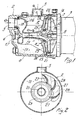
- figure 1 is a partially sectional side view of a first embodiment according to the invention;
- figure 2 is a sectional and partially exploded front view of the device of figure 1, taken along the line II-II;
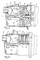
- figure 3 is a partially sectional side view of a second embodiment of the pump according to the invention;
- figure 4 is a partially sectional side view of an embodiment of the pump according to the invention which is similar to that of figure 3 in the case of a double impeller.
- With reference to figures 1 and 2, the pump according to the invention, generally indicated by the reference numeral 1, comprises a casing or
stator case 2 which has an essentially cylindrical shape and is provided with anintake port 3 defined on the front wall 4 and with adelivery port 5 arranged on the cylindrical side wall 6 in an upward position. Bothports - The
case 2 internally supports an impeller 7 which is keyed on ashaft 8 which is driven by the electric motor 9. The impeller 7, which has a per se known shape, has a hub 10, a crown 11 and a plurality of radial-centrifugal blades 12 with an appropriate profile. An inlet section 13 and anoutlet section 14 are defined at the ends of the set of blades of the impeller 7 and determine the direction of flow during the rotation of the impeller. - An ejector, generally indicated by the
reference numeral 16, is arranged in theinternal chamber 15 of thestator case 2 and comprises anentrainment nozzle 17 which is traversed by the recirculation flow Q₂, achamber 18 connected to theintake port 3 for drawing the useful flow Q₁, and adiffusion duct 19 in which the flows Q₁ and Q₂ are mixed and are subsequently conveyed through adivergent section 20 which is adjacent to the inlet of the impeller 7. - After the
outlet section 14 of the impeller 7 there is adiffuser 21 which is fixed to thecase 2 and hasblades 22 of a per se known shape. Re-conveyancechambers 23 are furthermore provided and direct the flow leaving the diffuser toward theinternal chamber 15 of the case. - According to a peculiar characteristic of the invention, after the impeller 7 and the
diffuser 21 there is a radial-centripetal conveyor, generally indicated by thereference numeral 24, which has an annular outlet section which extends peripherally to the diffusion duct of theejector 17. - In particular, the radial-
centripetal conveyor 24 is formed by a pair ofwalls case 2. - Inside said interspace there is a plurality of straightening
blades 27 of appropriate profile which determine a plurality ofconveyance channels 28 with an approximately constant transverse cross section. - The
conveyance channels 28 have an end portion which is substantially parallel to thediffusion duct 19 of the ejector, with a transverseannular outlet section 29 which is substantially perpendicular to the axis of the impeller. - The inner walls of the conveyance channels, particularly at the inlet and outlet portions, are accurately blended so that the outflowing liquid is as regularized as possible and approximately laminar, creating a roughly tubular fluid nappe which aids the separation of the air contained in the fluid mixture accelerated by the impeller and facilitates the migration of air toward the delivery port.
- The laminar outflow conditions furthermore facilitate the recirculation of the flow Q₂ toward the
ejection nozzle 17, increasing the efficiency of the ejector and consequently the flow Q₂ of the drawn liquid. This leads to a significant reduction in priming times, which by means of tests have been found to be comprised between 3.5 and 4.5 minutes. The efficiency of the pump in normal running conditions is furthermore also considerably increased up to 0.30-0.35. - Figures 3 and 4 illustrate a second embodiment of the pump according to the invention, wherein, differently from the first embodiment, the annular diffuser is not provided at the output of the impeller. In particular, figure 3 illustrates a single-stage pump and figure 4 illustrates a two-stage pump with double impeller. By analogy, the component elements which are identical to those of the first embodiment have been identified by the same reference numerals followed by a prime.
- The centripetal
radial conveyor 24′ of figure 3 is formed by thewalls 25′, 26′ and by the straighteningblades 27′ which define theconveyance channels 28′. - The
outflow cross section 29′ of the conveyor has an annular shape and is arranged peripherally to the outer portion of thediffusion duct 19′ of theejector 16′. - At the output of the impeller 7′, or of the impeller 7˝, the flow is deflected toward the
conveyor 24′ through a plurality of re-conveyance channels which comprise a series of radial-centripetal channels 30, a first axialannular duct 31, adjacent to the hub 11′ of the impeller 7′, an annular radial-centripetal duct 32 which extends parallel to the series of channels 30, and a second peripheral axialannular duct 33 which is connected to theconveyance channels 28′. - By means of this succession of re-conveyance channels, the flow is guided through the
channels 28′ of theconveyor 24′ and is directed into theinner chamber 15′ of thecase 2′. - In this case, too, the total flow rate Q produced by the
impeller 3′ is conveyed toward the central portion of the case adjacent to the outer wall of thediffusion duct 19′, in a position which is sufficiently distant from thedelivery port 5′ to facilitate the separation and migration of air toward thedelivery port 5′. - From the constructive point of view, the
conveyors blades - In practice it has been observed that the self-priming centrifugal pump according to the invention fully achieves the intended aim since it allows a drastic reduction of priming times and the obtainment of high operating efficiencies in normal running conditions.
- The self-priming centrifugal pump according to the invention is susceptible to numerous modifications and variations, all of which are within the scope of the inventive concept defined in the accompanying claims; all the details may furthermore be replaced with technically equivalent elements. In practice, the materials employed, so long as compatible with the specified use, as well as the dimensions and shapes, may be any according to the requirements and the state of the art.
Claims (10)
- a substantially cylindrical stator case (2);
- at least one bladed impeller (7) of the radial-centrifugal type;
- an intake port (3) and a delivery port (5) arranged on the walls (4, 6) of said case above the axis of said impeller (7);
- an ejector (16) arranged inside said case (2) and provided with a drawing chamber (18) connected to said intake port (3), with an entrainment nozzle (17) connected to the internal chamber (15) of said case and with a diffusion duct (19) which is coaxial to said impeller and is connected to the inlet thereof;
characterized in that it has, after said at least one impeller (7), a conveyor (24) which comprises at least one substantially radial conveyance channel (28) with an annular outflow section (29) which extends peripherally to the diffusion duct (19) of said ejector, said conveyor (24) having a configuration suitable for directing the flow which leaves said impeller toward a central portion of said case which is adjacent to the outer wall of said diffusion duct (19) and is distant from said delivery port (5) and for making said outflowing flow substantially laminar, so as to facilitate the separation of air and its migration toward said delivery port (5).
Applications Claiming Priority (2)
| Application Number | Priority Date | Filing Date | Title |
|---|---|---|---|
| IT8560589 | 1989-06-07 | ||
| IT8985605A IT1234116B (en) | 1989-06-07 | 1989-06-07 | SELF-PRIMING CENTRIFUGAL PUMP. |
Publications (3)
| Publication Number | Publication Date |
|---|---|
| EP0401670A2 true EP0401670A2 (en) | 1990-12-12 |
| EP0401670A3 EP0401670A3 (en) | 1991-07-03 |
| EP0401670B1 EP0401670B1 (en) | 1995-11-22 |
Family
ID=11328850
Family Applications (1)
| Application Number | Title | Priority Date | Filing Date |
|---|---|---|---|
| EP90110312A Expired - Lifetime EP0401670B1 (en) | 1989-06-07 | 1990-05-30 | Self-priming centrifugal pump |
Country Status (7)
| Country | Link |
|---|---|
| US (1) | US5100289A (en) |
| EP (1) | EP0401670B1 (en) |
| AT (1) | ATE130663T1 (en) |
| DE (1) | DE69023699T2 (en) |
| DK (1) | DK0401670T3 (en) |
| ES (1) | ES2079396T3 (en) |
| IT (1) | IT1234116B (en) |
Cited By (9)
| Publication number | Priority date | Publication date | Assignee | Title |
|---|---|---|---|---|
| EP0552661A1 (en) * | 1992-01-24 | 1993-07-28 | Ebara Corporation | Self priming centrifugal pump |
| DE4304149C1 (en) * | 1993-02-12 | 1994-09-08 | Grundfos As | Self-priming motor pump unit |
| DE29520422U1 (en) * | 1995-12-22 | 1997-04-30 | Speck Pumpenfabrik Walter Spec | Self-priming submersible centrifugal pump |
| WO1998023864A1 (en) | 1996-11-27 | 1998-06-04 | Calpeda S.P.A. | Diffuser and conveyor device for a single-impeller centrigugal self-priming pump |
| EP0936356A1 (en) | 1998-02-13 | 1999-08-18 | CALPEDA S.p.A. | Self-priming jet pump with flow control device |
| EP1219838A2 (en) * | 2000-11-14 | 2002-07-03 | CALPEDA S.p.A. | Guide wheel for centrifugal pumps |
| CN100451343C (en) * | 2006-01-19 | 2009-01-14 | 江苏大学 | Big-flow self-priming centrifugal pump |
| CN103148017A (en) * | 2013-04-02 | 2013-06-12 | 陈坚 | Air backflow prevention baffle of air guide sleeve of self-sucking injection pump |
| WO2020013729A1 (en) | 2018-07-10 | 2020-01-16 | Yazykov Andrey Yurievich | Centrifugal pump |
Families Citing this family (20)
| Publication number | Priority date | Publication date | Assignee | Title |
|---|---|---|---|---|
| DE9314532U1 (en) * | 1993-09-25 | 1993-12-09 | Stuebbe Asv Gmbh | Self-priming centrifugal pump |
| US5639222A (en) * | 1995-07-06 | 1997-06-17 | Wagner Spray Tech Corporation | Close coupled series turbine mounting |
| JP3584704B2 (en) * | 1997-10-24 | 2004-11-04 | 昭和風力機械株式会社 | Suction flow pre-swirl control bypass structure for blower |
| US6471476B1 (en) * | 2000-11-13 | 2002-10-29 | Wacker Corporation | Centrifugal trash pump |
| US6752597B2 (en) * | 2001-09-27 | 2004-06-22 | Lbt Company | Duplex shear force rotor |
| US20070258824A1 (en) * | 2005-02-01 | 2007-11-08 | 1134934 Alberta Ltd. | Rotor for viscous or abrasive fluids |
| US20080047861A1 (en) * | 2006-06-05 | 2008-02-28 | West John H | Product Development and Management Methodologies |
| US7426896B2 (en) * | 2006-06-05 | 2008-09-23 | Bomboard Llc | Prone operator position personal watercraft |
| US20080089777A1 (en) * | 2006-08-30 | 2008-04-17 | Lang John P | Self-priming adapter apparatus and method |
| JP4274230B2 (en) * | 2006-11-21 | 2009-06-03 | パナソニック電工株式会社 | pump |
| CN101929465B (en) * | 2009-06-19 | 2013-12-11 | 德昌电机(深圳)有限公司 | Drainage pump |
| JP5839803B2 (en) * | 2011-01-24 | 2016-01-06 | 三菱重工業株式会社 | Bypass energy recovery device for fluid machinery |
| US9695826B1 (en) | 2012-06-28 | 2017-07-04 | James Harmon | Pitot tube pump and related methods |
| ES2460369B1 (en) * | 2012-11-12 | 2015-03-02 | Coprecitec Sl | Fluid circulation pump adapted for an appliance |
| US10036401B2 (en) * | 2015-04-17 | 2018-07-31 | Caterpillar Inc. | Recirculating pump inlet |
| CN106523438B (en) * | 2017-01-12 | 2018-10-23 | 浙江神农泵业有限公司 | A kind of split type baffle of jet pump |
| EP4118338A1 (en) * | 2020-04-03 | 2023-01-18 | Zodiac Pool Systems LLC | Swimming pool and spa pumps configured to improve priming performance |
| CN112648242A (en) * | 2021-01-18 | 2021-04-13 | 台州市中积智能装备有限公司 | Jet pump with inner flow guide structure |
| CN115182883B (en) * | 2022-07-12 | 2024-01-02 | 宁波君禾智能科技有限公司 | Self-priming pump |
| CN115199594A (en) * | 2022-07-14 | 2022-10-18 | 兰州理工大学 | Jet self-priming pump |
Citations (6)
| Publication number | Priority date | Publication date | Assignee | Title |
|---|---|---|---|---|
| US2424285A (en) * | 1941-05-31 | 1947-07-22 | Jacuzzi Bros Inc | Pump and pump system |
| US2631539A (en) * | 1947-11-21 | 1953-03-17 | Dayton Pump & Mfg Co | Pump |
| US2941474A (en) * | 1956-08-20 | 1960-06-21 | Fairbanks Morse & Co | Self-priming pumping apparatus |
| DE3718273A1 (en) * | 1986-09-01 | 1988-03-10 | Pumpen & Verdichter Veb K | Separating device |
| EP0323384A2 (en) * | 1987-12-28 | 1989-07-05 | Bombas Electricas, S.A. (Boelsa) | Centrifugal pump |
| EP0361328A1 (en) * | 1988-09-26 | 1990-04-04 | CALPEDA S.p.A. | Self-priming jet pump with an axial diffuser |
Family Cites Families (8)
| Publication number | Priority date | Publication date | Assignee | Title |
|---|---|---|---|---|
| CA536144A (en) * | 1957-01-22 | Jacuzzi Candido | Self-priming deep well pumping system | |
| FR323384A (en) * | 1902-08-01 | 1903-03-05 | Allg Beleuchtungs Und Heizindu | Petroleum incandescent burner |
| US2444100A (en) * | 1944-02-28 | 1948-06-29 | Marison Company | Pump |
| US2524269A (en) * | 1946-10-14 | 1950-10-03 | Sta Rite Products Inc | Pump |
| US2855143A (en) * | 1954-02-16 | 1958-10-07 | Sulzer Ag | Multistage radial flow turbomachine |
| US2853014A (en) * | 1956-02-28 | 1958-09-23 | Fred A Carpenter | Booster attachment for centrifugal pumps |
| US2934021A (en) * | 1956-10-09 | 1960-04-26 | F E Meyers & Bro Co | Shallow well self-priming jet pump |
| US2945448A (en) * | 1957-02-15 | 1960-07-19 | Bell & Gossett Co | Universal centrifugal pump |
-
1989
- 1989-06-07 IT IT8985605A patent/IT1234116B/en active
-
1990
- 1990-05-30 DE DE69023699T patent/DE69023699T2/en not_active Expired - Fee Related
- 1990-05-30 AT AT90110312T patent/ATE130663T1/en not_active IP Right Cessation
- 1990-05-30 ES ES90110312T patent/ES2079396T3/en not_active Expired - Lifetime
- 1990-05-30 DK DK90110312.7T patent/DK0401670T3/en active
- 1990-05-30 EP EP90110312A patent/EP0401670B1/en not_active Expired - Lifetime
-
1991
- 1991-07-05 US US07/727,393 patent/US5100289A/en not_active Expired - Lifetime
Patent Citations (6)
| Publication number | Priority date | Publication date | Assignee | Title |
|---|---|---|---|---|
| US2424285A (en) * | 1941-05-31 | 1947-07-22 | Jacuzzi Bros Inc | Pump and pump system |
| US2631539A (en) * | 1947-11-21 | 1953-03-17 | Dayton Pump & Mfg Co | Pump |
| US2941474A (en) * | 1956-08-20 | 1960-06-21 | Fairbanks Morse & Co | Self-priming pumping apparatus |
| DE3718273A1 (en) * | 1986-09-01 | 1988-03-10 | Pumpen & Verdichter Veb K | Separating device |
| EP0323384A2 (en) * | 1987-12-28 | 1989-07-05 | Bombas Electricas, S.A. (Boelsa) | Centrifugal pump |
| EP0361328A1 (en) * | 1988-09-26 | 1990-04-04 | CALPEDA S.p.A. | Self-priming jet pump with an axial diffuser |
Cited By (12)
| Publication number | Priority date | Publication date | Assignee | Title |
|---|---|---|---|---|
| EP0552661A1 (en) * | 1992-01-24 | 1993-07-28 | Ebara Corporation | Self priming centrifugal pump |
| US5451139A (en) * | 1992-01-24 | 1995-09-19 | Ebara Corporation | Self priming centrifugal |
| DE4304149C1 (en) * | 1993-02-12 | 1994-09-08 | Grundfos As | Self-priming motor pump unit |
| DE29520422U1 (en) * | 1995-12-22 | 1997-04-30 | Speck Pumpenfabrik Walter Spec | Self-priming submersible centrifugal pump |
| WO1998023864A1 (en) | 1996-11-27 | 1998-06-04 | Calpeda S.P.A. | Diffuser and conveyor device for a single-impeller centrigugal self-priming pump |
| EP0936356A1 (en) | 1998-02-13 | 1999-08-18 | CALPEDA S.p.A. | Self-priming jet pump with flow control device |
| EP1219838A2 (en) * | 2000-11-14 | 2002-07-03 | CALPEDA S.p.A. | Guide wheel for centrifugal pumps |
| EP1219838A3 (en) * | 2000-11-14 | 2002-07-10 | CALPEDA S.p.A. | Guide wheel for centrifugal pumps |
| CN100451343C (en) * | 2006-01-19 | 2009-01-14 | 江苏大学 | Big-flow self-priming centrifugal pump |
| CN103148017A (en) * | 2013-04-02 | 2013-06-12 | 陈坚 | Air backflow prevention baffle of air guide sleeve of self-sucking injection pump |
| CN103148017B (en) * | 2013-04-02 | 2016-05-04 | 陈坚 | The baffle plate that the air-prevention of self-suction injection pump kuppe flows backwards |
| WO2020013729A1 (en) | 2018-07-10 | 2020-01-16 | Yazykov Andrey Yurievich | Centrifugal pump |
Also Published As
| Publication number | Publication date |
|---|---|
| DK0401670T3 (en) | 1995-12-18 |
| IT8985605A0 (en) | 1989-06-07 |
| US5100289A (en) | 1992-03-31 |
| IT1234116B (en) | 1992-04-29 |
| DE69023699D1 (en) | 1996-01-04 |
| DE69023699T2 (en) | 1996-07-25 |
| ES2079396T3 (en) | 1996-01-16 |
| EP0401670B1 (en) | 1995-11-22 |
| EP0401670A3 (en) | 1991-07-03 |
| ATE130663T1 (en) | 1995-12-15 |
Similar Documents
| Publication | Publication Date | Title |
|---|---|---|
| EP0401670B1 (en) | Self-priming centrifugal pump | |
| CN108350907B (en) | Low cavitation erosion impeller and pump | |
| US3444817A (en) | Fluid pump | |
| CA2911772C (en) | Nozzle-shaped slots in impeller vanes | |
| US3817659A (en) | Pitot pump with jet pump charging system | |
| US4642023A (en) | Vented shrouded inducer | |
| EP2474743A3 (en) | Barrel-type multistage pump | |
| US5549451A (en) | Impelling apparatus | |
| EP0552661B1 (en) | Self priming centrifugal pump | |
| KR20150120168A (en) | Centrifugal type mixed flow blower | |
| CN107407283A (en) | Self-priming pump | |
| US4627792A (en) | Rotating flow pump with a feed pump unit formed as an ejector | |
| US4252499A (en) | Centrifugal pump | |
| US1629141A (en) | Hydraulic pump | |
| US2677327A (en) | Centrifugal pump construction | |
| EP0936356B1 (en) | Self-priming jet pump with flow control device | |
| KR101607502B1 (en) | Centrifugal pump | |
| EP0879360B1 (en) | Diffuser and conveyor device for a single-impeller centrigugal self-priming pump | |
| US3204562A (en) | Anti gas-lock construction for turbine pump | |
| EP3850219B1 (en) | Self-priming centrifugal pump | |
| ES2006285A6 (en) | Centrifugal pump. | |
| US3045603A (en) | Self-priming centrifugal pump | |
| US3374747A (en) | Self-priming device and method for pumps | |
| US4401409A (en) | Self-priming centrifugal pump | |
| EP0093483A2 (en) | Centrifugal pump |
Legal Events
| Date | Code | Title | Description |
|---|---|---|---|
| PUAI | Public reference made under article 153(3) epc to a published international application that has entered the european phase |
Free format text: ORIGINAL CODE: 0009012 |
|
| AK | Designated contracting states |
Kind code of ref document: A2 Designated state(s): AT BE CH DE DK ES FR GB GR IT LI LU NL SE |
|
| PUAL | Search report despatched |
Free format text: ORIGINAL CODE: 0009013 |
|
| AK | Designated contracting states |
Kind code of ref document: A3 Designated state(s): AT BE CH DE DK ES FR GB GR IT LI LU NL SE |
|
| 17P | Request for examination filed |
Effective date: 19911213 |
|
| 17Q | First examination report despatched |
Effective date: 19930730 |
|
| RAP1 | Party data changed (applicant data changed or rights of an application transferred) |
Owner name: EBARA CORPORATION |
|
| GRAA | (expected) grant |
Free format text: ORIGINAL CODE: 0009210 |
|
| AK | Designated contracting states |
Kind code of ref document: B1 Designated state(s): AT BE CH DE DK ES FR GB GR IT LI LU NL SE |
|
| PG25 | Lapsed in a contracting state [announced via postgrant information from national office to epo] |
Ref country code: NL Free format text: LAPSE BECAUSE OF FAILURE TO SUBMIT A TRANSLATION OF THE DESCRIPTION OR TO PAY THE FEE WITHIN THE PRESCRIBED TIME-LIMIT Effective date: 19951122 Ref country code: LI Effective date: 19951122 Ref country code: GR Free format text: LAPSE BECAUSE OF FAILURE TO SUBMIT A TRANSLATION OF THE DESCRIPTION OR TO PAY THE FEE WITHIN THE PRESCRIBED TIME-LIMIT Effective date: 19951122 Ref country code: FR Effective date: 19951122 Ref country code: CH Effective date: 19951122 Ref country code: BE Effective date: 19951122 Ref country code: AT Effective date: 19951122 |
|
| REF | Corresponds to: |
Ref document number: 130663 Country of ref document: AT Date of ref document: 19951215 Kind code of ref document: T |
|
| ITF | It: translation for a ep patent filed |
Owner name: ING. ZINI MARANESI & C. S.R.L. |
|
| REG | Reference to a national code |
Ref country code: DK Ref legal event code: T3 |
|
| REF | Corresponds to: |
Ref document number: 69023699 Country of ref document: DE Date of ref document: 19960104 |
|
| REG | Reference to a national code |
Ref country code: ES Ref legal event code: FG2A Ref document number: 2079396 Country of ref document: ES Kind code of ref document: T3 |
|
| PG25 | Lapsed in a contracting state [announced via postgrant information from national office to epo] |
Ref country code: SE Effective date: 19960222 |
|
| EN | Fr: translation not filed | ||
| NLV1 | Nl: lapsed or annulled due to failure to fulfill the requirements of art. 29p and 29m of the patents act | ||
| PG25 | Lapsed in a contracting state [announced via postgrant information from national office to epo] |
Ref country code: GB Effective date: 19960530 |
|
| PG25 | Lapsed in a contracting state [announced via postgrant information from national office to epo] |
Ref country code: LU Free format text: LAPSE BECAUSE OF NON-PAYMENT OF DUE FEES Effective date: 19960531 |
|
| REG | Reference to a national code |
Ref country code: CH Ref legal event code: PL |
|
| PLBE | No opposition filed within time limit |
Free format text: ORIGINAL CODE: 0009261 |
|
| STAA | Information on the status of an ep patent application or granted ep patent |
Free format text: STATUS: NO OPPOSITION FILED WITHIN TIME LIMIT |
|
| 26N | No opposition filed | ||
| GBPC | Gb: european patent ceased through non-payment of renewal fee |
Effective date: 19960530 |
|
| PGFP | Annual fee paid to national office [announced via postgrant information from national office to epo] |
Ref country code: DK Payment date: 20060516 Year of fee payment: 17 |
|
| PGFP | Annual fee paid to national office [announced via postgrant information from national office to epo] |
Ref country code: DE Payment date: 20060525 Year of fee payment: 17 |
|
| PGFP | Annual fee paid to national office [announced via postgrant information from national office to epo] |
Ref country code: ES Payment date: 20060526 Year of fee payment: 17 |
|
| PGFP | Annual fee paid to national office [announced via postgrant information from national office to epo] |
Ref country code: IT Payment date: 20060531 Year of fee payment: 17 |
|
| REG | Reference to a national code |
Ref country code: DK Ref legal event code: EBP |
|
| PG25 | Lapsed in a contracting state [announced via postgrant information from national office to epo] |
Ref country code: DK Free format text: LAPSE BECAUSE OF NON-PAYMENT OF DUE FEES Effective date: 20070531 Ref country code: DE Free format text: LAPSE BECAUSE OF NON-PAYMENT OF DUE FEES Effective date: 20071201 |
|
| REG | Reference to a national code |
Ref country code: ES Ref legal event code: FD2A Effective date: 20070531 |
|
| PG25 | Lapsed in a contracting state [announced via postgrant information from national office to epo] |
Ref country code: ES Free format text: LAPSE BECAUSE OF NON-PAYMENT OF DUE FEES Effective date: 20070531 |
|
| PG25 | Lapsed in a contracting state [announced via postgrant information from national office to epo] |
Ref country code: IT Free format text: LAPSE BECAUSE OF NON-PAYMENT OF DUE FEES Effective date: 20070530 |