EP0401190A2 - Press section of a paper or board machine - Google Patents
Press section of a paper or board machine Download PDFInfo
- Publication number
- EP0401190A2 EP0401190A2 EP90850218A EP90850218A EP0401190A2 EP 0401190 A2 EP0401190 A2 EP 0401190A2 EP 90850218 A EP90850218 A EP 90850218A EP 90850218 A EP90850218 A EP 90850218A EP 0401190 A2 EP0401190 A2 EP 0401190A2
- Authority
- EP
- European Patent Office
- Prior art keywords
- roll
- press
- nip
- centre
- crown
- Prior art date
- Legal status (The legal status is an assumption and is not a legal conclusion. Google has not performed a legal analysis and makes no representation as to the accuracy of the status listed.)
- Granted
Links
Images
Classifications
-
- D—TEXTILES; PAPER
- D21—PAPER-MAKING; PRODUCTION OF CELLULOSE
- D21F—PAPER-MAKING MACHINES; METHODS OF PRODUCING PAPER THEREON
- D21F3/00—Press section of machines for making continuous webs of paper
- D21F3/02—Wet presses
- D21F3/04—Arrangements thereof
Definitions
- the invention concerns a press section of a paper or board machine, comprising a number of rolls which form press nips that dewater the web with each other, the web being arranged to run through said nips, and of which said rolls at least one roll is a smooth-faced so-called centre roll, which forms a press nip with at least one other press roll, over which a press felt, which has been formed as an endless loop, is passed to absorb water out of the web into said press felt.
- a web is formed in the former of the paper machine, whereupon the formed web is passed, being supported and carried by the felts in the paper machine, into the press section of the paper machine, wherein both the web and the felts that support it are passed through nips formed by the rolls in the press section to absorb water out of the web into the felts. From the press section the web is passed further into the drying section of the paper machine.
- a conventional solution in a press section comprises a large and massive centre roll as well as wire or felt loops grouped around it, the rolls placed inside said loops forming press nips either with one another or together with the centre roll, and when the web runs through said press nips, water is drained out of the web by the effect of compression, said water being absorbed into the felts.
- water is removed out of the web by means of evaporation, which is highly energy-consuming and therefore expensive and uneconomical. This is why attempts are made to remove a maximal proportion of water out of the web before the drying section, in the press section, by mechanical means.
- a conventional construction in the press section of a paper machine wherein a centre roll and press rolls grouped around it are employed constitutes three press nips.
- the first press nip is formed between a grooved roll and a press-suction roll.
- the second press nips is formed between a press-suction roll and the centre roll
- the third press nip is formed between the centre roll and a second grooved roll. Since, in the nips in the press section, it must be possible to make the linear loads as uniform as possible, in such a solution, as a rule, said grooved rolls have been formed as variable-crown rolls, preferably as rolls adjustable in zones.
- the object of the present invention is to provide a press section by means of which the drawbacks described above are minimized and by means of which an essential improvement is obtained in respect of increased dry solids content and increased running speed.
- a further object is to provide a construction to substitute for the rock rolls employed in presses.
- the centre roll is a variable-crown roll, which comprises a metallic roll mantle arranged revolving on a stationary roll axle as well as at least one set of crown-variation means, which are arranged to load the roll mantle in the direction of the nip plane of the centre roll and the roll that forms a press nip with said centre roll so asto regulate the profile of linear load in said nip.
- the mantle of the centre roll can be made thinner than in prior art, whereby it has an improved thermal conductivity.
- the roll can also be used for heating the web.
- An additional advantage obtainable by means of the invention is related to the construction of the grooved rolls that are used to-day.
- the grooved rolls are made so that they are provided with a suitable coating, e.g. of polyurethane. It results from this that they have a limited ability to tolerate heat.
- Variable-crown rolls and in particular rolls adjustable in zones, however, develop a considerable amount of heat. Since, when a solution in accordance with the invention is used, the grooved rolls do not have to be variable-crown rolls, if necessary, they can be provided with cooling in a simple way. As a further, additional advantage can be stated that the invention can be applied as such as an after-installation to existing presses. The further advantages and characteristic features of the invention come out from the following detailed description of the invention.
- the web W in is formed on the wire 50, which is either a fourdrinier wire or the carrying wire of a twin-wire former.
- the wire 50 On the downwards inclined run of the wire 50 between the wire suction roll 51 and the wire draw roll 52, the web in is transferred on the detaching line P on the suction zone 14 of the pick-up roll 13 onto the first press felt 10, which, thus, also acts as the pick-up felt.
- the first press felt 10 carries the web in on its lower face into the first press nip N1, which is formed between two press rolls, i.e. a press-suction roll 11 and a grooved roll 22 or an equivalent roll provided with a hollow face 23.
- the first press felt 10 forms an endless loop by means of guide and alignment rolls (not shown), which also keep said first press felt 10 appropriately tensioned.
- the first nip N1 is provided with two press felts, i.e. said first press felt 10 and a second press felt 20, the latter felt also forming an endless loop by means of guide and alignment rolls 21, which keep said second press felt 20 appropriately tensioned.
- the nip plane of the first nip N1 is denoted with the reference denotation K1.
- the web in is sucked by means of the suction zone 12 of the press-suction roll 11 out of contact with the second press felt 20 onto the face of the first press felt 10 and, being guided by the press-suction roll 11, into the second nip N2.
- a so-called pick-up felt is used as said first press felt, and the press-suction roll is provided with a suction zone 12 of appropriate length, which ensures the detaching of the web in from the second press felt 20 onto the face of the first press felt 10.
- the second nip N2 is formed between the press-suction roll 11 and the centre roll 1 in the press section. After the second nip N2, said first press felt 10 is passed away from the centre roll 1.
- the web in is detached after the second nip N2 from the first press felt and adheres to the face of said centre roll, under whose guidance the web in is hereupon transferred into the third nip N3 in the press section.
- the third nip N3 is formed between the centre roll 1 and an opposite grooved roll 32 or an equivalent roll provided with a hollow face 33. Over said grooved roll 32, a third press felt 30 is passed, which is formed as an endless loop by means of guide and alignment rolls 31.
- the press section further includes a fourth, separate press, in which case the fourth nip N4 in the press is formed between a second centre roll 70, corresponding to the centre roll 1, and an opposite grooved roll 44 or an equivalent roll provided with a hollow face 45.
- the third nip N3 the web in is detached from the third press felt 30 onto the face of the centre roll 1, from which it is detached by means of a transfer-suction roll 63.
- a transfer-suction roll 63 an open draw is formed between the centre roll 1 and said transfer-suction roll 63.
- the transfer-suction roll 63 the web in is transferred onto the fourth press felt 40 on the suction zone 42 of the suction roll 41, which acts as a pick-up roll.
- the fourth press felt 40 is also a so-called pick-up felt.
- the fourth press felt 40 is formed as an endless loop by. means of guide and alignment rolls 43. Said fourth press felt 40 transfers the web in into the fourth press nip N4, after which, owing to the surface properties of the second centre roll 70, the web in is detached from the fourth press felt 40 onto the face of the second centre roll 70.
- the nip plane of the fourth nip N4 is denoted with the reference denotation K4. From the second centre roll 70, the web in is transferred onto the drying wire 60 by means of transfer-suction rolls 61 and 62, while the drying wire 60 transfers the web in further into the drying section (not shown).
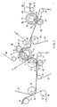
- Fig. 1 shows a first preferred embodiment of a press section in accordance with the invention.
- the centre roll 1 in the press section is a variable-crown roll, which comprises a metallic roll mantle 2 which is arranged as revolving on a stationary roll axle 3.
- crown-variation means 4 and 5 are inside the centre roll 1, fitted which act in the nip plane K2 of the second nip N2 as well as in the nip plane K3 of the third nip N3, by means of which said means the roll mantle 2 is loaded in said nip planes K2 and K3 to produce the desired profile of linear load.
- Fig. 1 shows a first preferred embodiment of a press section in accordance with the invention.
- the centre roll 1 in the press section is a variable-crown roll, which comprises a metallic roll mantle 2 which is arranged as revolving on a stationary roll axle 3.
- crown-variation means 4 and 5 are. fitted which act in the
- said crown-variation means comprise loading shoes supported on the roll axle 3 and acting upon the inner face of the roll mantle 2.
- the centre roll 1 is a roll adjustable in zones, wherein the crown variation is provided in two directions, which form an angle a with each other.
- regulation of the profile of linear loads is accomplished both in the second and in the third nip N2 and N3 in the press section. Since, in the centre roll in accordance with Fig. 1, there are two directions of crown variation, as the crown-variation means 4 and 5 it is necessary to employ exactly the above loading-shoe constructions.
- crown variation were provided in the centre roll 1 in one direction only, either in the nip plane K2 of the second nip N2 or in the nip plane K3 of the third nip N3, in this direction it would be possible to employ any crown-variation means accomplished by means of the present-day technique as the crown-variation means.
- Fig. 1 this has not been shown, but, if necessary, it would also be possible to provide crown-variation means in the grooved roll 22, in which case the profile of linear loads could also be brought under control in the first part N1 of the press section.
- the press section shown in Fig. 1 also includes a fourth press nip N4 constituted by a separate press.
- the second centre roll 70 is arranged as a variable-crown roll, so that the second centre roll 70 comprises a hollow, metallic roll mantle 71, which is arranged revolving on a stationary roll axle 72.
- crown-variation means 73 are provided, by whose means the fourth nip N4 is loaded in the direction of the nip plane k4 to produce the desired profile of linear loads.
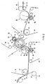
- the second embodiment of the invention shown in Fig. 2 differs from that shown in Fig. 1 in the respect that, in the centre roll 1, crown-variation means 4 are provided in the nip plane K2 of the second nip N2 only. Owing to this, in the embodiment shown in Fig. 2, as crown-variation means 4 it is possible to use any construction whatsoever that can be accomplished by means of the present-day technique. In Fig. 2, it is shown additionally that in this embodiment the profile of linear loads is also regulated in the first nip N1 in the direction of the nip plane K1 so that the grooved roll 22 is formed as a variable-crown roll.
- the grooved roll 22 comprises a tubular roll mantle 24, which is mounted as revolving on the stationary roll axle 25.
- the necessary crown-variation means 26 are provided inside the roll mantle 24, to regulate the profile of linear loads in the nip N1. Since herein one direction of regulation only is concerned, as crown-variation means it is possible to use any regulation means that can be accomplished, e.g., by means of the present-day technique.
- the grooved roll 32 in said third nip N3 is formed as a variable-crown roll, whose construction corresponds to that of the grooved roll 22 in the first nip N1 described above.
- the grooved roll 32 comprises a tubular roll mantle 34, which is arranged revolving on the roll axle 35.
- crown-variation means 36 are provided, which act in the nip plane K3 of the third nip N3 to regulate the profile of linear loads.
- the crown-variation means 36 can be accomplished in any desired way.
- the crown-variation means 36 it is possible to employ, for example, the loading shoes shown in Fig. 2, but in their place it is also possible to use, for example, a chamber of pressure fluid or a series of chambers provided between the roll axle 35 and the roll mantle 34.
- the regulation of the profile of linear loads is arranged in a way differing from Fig. 1.
- Fig. 1 In the embodiment shown in Fig.
- the grooved roll 44 in the fourth nip N4 is arranged as a variable-crown roll so that the roll 44 comprises a tubular roll mantle 46, which is arranged revolving on the axle 47 of the roll mantle.
- crown-variation means 48 similar to those described above in connection with the crown-variation means 26 and 36 of the grooved rolls 22 and 32 in the first nip N1 and in the third nip N3 are provided.
- a fully conventional metal roll or even a rock roll as the centre roll 70.
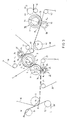
- the third embodiment of the invention is in a way a combination of the embodiments shown in Figs. 1 and 2.
- the regulations of the profiles of linear loads in the first, second and third nip N1,N2,N3 in the press section are accomplished in the same ways as in the solution shown in Fig. 2, and in the fourth nip N4 in the same way as is shown in Fig. 1.
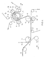
- the embodiment shown in Fig. 4 differs from the above embodiments as follows.
- the solution is similar to that described in the above embodiments.
- the second nip N2 in the press section is not formed between the press-suction roll 11 and the centre roll 1, but in this embodiment, on the run of the first press felt 10 after the press-suction roll 11, a grooved roll 15 or an equivalent roll provided with a hollow face 16 is provided, which forms the second nip N2 in the press section with the centre roll 1.
- the first press felt 10 is formed as an endless loop, as is the case in the above embodiments, by means of guide and alignment rolls 17.
Abstract
Description
- The invention concerns a press section of a paper or board machine, comprising a number of rolls which form press nips that dewater the web with each other, the web being arranged to run through said nips, and of which said rolls at least one roll is a smooth-faced so-called centre roll, which forms a press nip with at least one other press roll, over which a press felt, which has been formed as an endless loop, is passed to absorb water out of the web into said press felt.
- In a paper machine, out of fibre pulp, a web is formed in the former of the paper machine, whereupon the formed web is passed, being supported and carried by the felts in the paper machine, into the press section of the paper machine, wherein both the web and the felts that support it are passed through nips formed by the rolls in the press section to absorb water out of the web into the felts. From the press section the web is passed further into the drying section of the paper machine. A conventional solution in a press section comprises a large and massive centre roll as well as wire or felt loops grouped around it, the rolls placed inside said loops forming press nips either with one another or together with the centre roll, and when the web runs through said press nips, water is drained out of the web by the effect of compression, said water being absorbed into the felts. In the drying section, water is removed out of the web by means of evaporation, which is highly energy-consuming and therefore expensive and uneconomical. This is why attempts are made to remove a maximal proportion of water out of the web before the drying section, in the press section, by mechanical means. It is known in prior art that water is removed out of the web considerably more readily at a raised temperature, because the viscosity of water and the springback coefficient of the web are thereby lowered together with the surface tension. Owing to this, it has been possible already to raise the temperature of the web in the press section. Based on earlier experience, it can be established that, e.g., an increase in thetemperature by 6...10oC in the press section produces an increase of an order of 1 or more in the dry solids content of the web. An increased dry solids content in the press section produces considerable economies of costs. For example, in paper machines it can be considered a rough rule that, if the moisture content in the web in the press section can be lowered by 1 %, the consumption of steam in the drying section is lowered by about 5 %.
- One drawback, which has been recognized for quite a long time, in the press sections which are used commonly to-day consists of the centre roll in the press section, as whose material, as a rule, some suitable rock, such as granite, is used. As is well known, rock rolls are quite sensitive to large and sudden changes in temperature, and the effects of such changes may be quite fatal. This is why attempts have been made to develop suitable substitutes for granite rolls. As substitutes for rock rolls, e.g., such metal rolls have been used as are coated, e.g., with a mixture of polyurethane and rock dust to make the surface properties of the roll similar to those of a rock roll. Advantages of metal rolls compared with rock rolls include their considerably better ability to tolerate variations in temperature. Moreover, owing to this, they can be run as considerably hotter than rock rolls. Moreover, a metal roll tolerates considerably higher running speeds than rock rolls do.
- A conventional construction in the press section of a paper machine wherein a centre roll and press rolls grouped around it are employed constitutes three press nips. In such a construction, the first press nip is formed between a grooved roll and a press-suction roll. On the other hand, the second press nips is formed between a press-suction roll and the centre roll, and the third press nip is formed between the centre roll and a second grooved roll. Since, in the nips in the press section, it must be possible to make the linear loads as uniform as possible, in such a solution, as a rule, said grooved rolls have been formed as variable-crown rolls, preferably as rolls adjustable in zones. Thus, owing to the crown variation of the grooved rolls, in the first nip and in the third nip in the press section, a uniform linear load is achieved. In order that a linear load as uniform as possible could also be obtained for the second press nip, the mantles of the press-suction roll and the centre roll, which form the second press nip, are, as a rule, cam bered. By means of the camber, a uniform linear load is, however, never obtained for a nip and, moreover, it is a further drawback of the cambering that the camber is always "fixed". If the camber has to be changed, the roll must always be ground. This is again quite a costly and laborious operation. Since cambering alone does not bring the profile of linear load under full control, for example, a problem of the metallic centre rolls in use at present has been uneven heating. This has caused distortions of the profile of linear load. Since the grooved rolls are provided with crown-variation means, the grooved rolls have been highly expensive. In this respect, the high cost has also been contributed to by the fact that it has been difficult to fit the crown-variation means inside a grooved roll, because the diameters of the grooved rolls are relatively small. If a fourth, separate press has been added to such a press section, in this press a variable-crown grooved roll has also been used.
- Thus, as a summary of the drawbacks related to prior art, it is possible to mention the high cost of the construction, the problems of temperature related to the construction, as well as the difficulties in providing uniform and, if necessary, adjustable profiles of linear loads.
- The object of the present invention is to provide a press section by means of which the drawbacks described above are minimized and by means of which an essential improvement is obtained in respect of increased dry solids content and increased running speed. A further object is to provide a construction to substitute for the rock rolls employed in presses. In view of achieving these objectives, the solution in accordance with the invention is mainly characterized in that the centre roll is a variable-crown roll, which comprises a metallic roll mantle arranged revolving on a stationary roll axle as well as at least one set of crown-variation means, which are arranged to load the roll mantle in the direction of the nip plane of the centre roll and the roll that forms a press nip with said centre roll so asto regulate the profile of linear load in said nip.
- Compared with prior art, by means of the invention, a number of advantages are obtained, which were partly already discussed above. Of the differences, for example, the following should be mentioned additionally. With the use of the solution in accordance with the invention, if necessary, two variable-crown rolls can be substituted for by one variable-crown roll. This results in considerable economies. Since the crown-variation means are used expressly in connection with the centre roll, it is considerably easier to construct these means in the interior of the roll, because the available space is larger. With the use of the present invention, if desirable, it is also possible to control the profile of linear loads in the nip between a press-suction roll and the centre roll.
- Moreover, by means of the solution in accordance with the invention, those problems are avoided that are related to the uneven heating of the prior-art metallic centre rolls. When a solution in accordance with the invention is used, the mantle of the centre roll can be made thinner than in prior art, whereby it has an improved thermal conductivity. If desired, the roll can also be used for heating the web. Nor is it necessary to grind any camber on a roll in accordance with the invention. An additional advantage obtainable by means of the invention is related to the construction of the grooved rolls that are used to-day. Currently, the grooved rolls are made so that they are provided with a suitable coating, e.g. of polyurethane. It results from this that they have a limited ability to tolerate heat. Variable-crown rolls, and in particular rolls adjustable in zones, however, develop a considerable amount of heat. Since, when a solution in accordance with the invention is used, the grooved rolls do not have to be variable-crown rolls, if necessary, they can be provided with cooling in a simple way. As a further, additional advantage can be stated that the invention can be applied as such as an after-installation to existing presses. The further advantages and characteristic features of the invention come out from the following detailed description of the invention.
- In the following, the invention will be described in detail with reference to the figures in the accompanying drawing.
- Figure 1 is a schematical side view of the press section of a paper or board machine wherein a solution of the invention is applied.
- Figure 2 is a corresponding view of an embodiment alternative of the solution shown in Fig. 1.
- Figure 3 is a corresponding view of a further embodiment alternative of the solutions shown in Figs. 1 and 2.
- Figure 4 shows a further alternative embodiment of the solution in accordance with the invention.
- As is shown in Figs. 1,2 and 3, the web W in is formed on the
wire 50, which is either a fourdrinier wire or the carrying wire of a twin-wire former. On the downwards inclined run of thewire 50 between thewire suction roll 51 and thewire draw roll 52, the web in is transferred on the detaching line P on thesuction zone 14 of the pick-up roll 13 onto the first press felt 10, which, thus, also acts as the pick-up felt. The first press felt 10 carries the web in on its lower face into the first press nip N₁, which is formed between two press rolls, i.e. a press-suction roll 11 and agrooved roll 22 or an equivalent roll provided with ahollow face 23. The first press felt 10 forms an endless loop by means of guide and alignment rolls (not shown), which also keep said first press felt 10 appropriately tensioned. The first nip N₁ is provided with two press felts, i.e. said first press felt 10 and a second press felt 20, the latter felt also forming an endless loop by means of guide andalignment rolls 21, which keep said second press felt 20 appropriately tensioned. The nip plane of the first nip N₁ is denoted with the reference denotation K₁. - After the first nip N₁ the web in is sucked by means of the
suction zone 12 of the press-suction roll 11 out of contact with the second press felt 20 onto the face of the first press felt 10 and, being guided by the press-suction roll 11, into the second nip N₂. For this purpose, a so-called pick-up felt is used as said first press felt, and the press-suction roll is provided with asuction zone 12 of appropriate length, which ensures the detaching of the web in from the second press felt 20 onto the face of the first press felt 10. The second nip N₂ is formed between the press-suction roll 11 and the centre roll 1 in the press section. After the second nip N₂, said first press felt 10 is passed away from the centre roll 1. Owing to the surface properties of the centre roll 1 (smooth-faced roll), the web in is detached after the second nip N₂ from the first press felt and adheres to the face of said centre roll, under whose guidance the web in is hereupon transferred into the third nip N₃ in the press section. The third nip N₃ is formed between the centre roll 1 and an oppositegrooved roll 32 or an equivalent roll provided with ahollow face 33. Over saidgrooved roll 32, a third press felt 30 is passed, which is formed as an endless loop by means of guide and alignment rolls 31. - In the embodiments shown in Figs. 1,2 and 3, the press section further includes a fourth, separate press, in which case the fourth nip N₄ in the press is formed between a
second centre roll 70, corresponding to the centre roll 1, and an oppositegrooved roll 44 or an equivalent roll provided with ahollow face 45. After the third nip N₃ the web in is detached from the third press felt 30 onto the face of the centre roll 1, from which it is detached by means of a transfer-suction roll 63. Thus, an open draw is formed between the centre roll 1 and said transfer-suction roll 63. From the transfer-suction roll 63 the web in is transferred onto the fourth press felt 40 on thesuction zone 42 of thesuction roll 41, which acts as a pick-up roll. Between the transfer-suction roll 63 and thesuction roll 41, there is also an open draw. The fourth press felt 40 is also a so-called pick-up felt. The fourth press felt 40 is formed as an endless loop by. means of guide and alignment rolls 43. Said fourth press felt 40 transfers the web in into the fourth press nip N₄, after which, owing to the surface properties of thesecond centre roll 70, the web in is detached from the fourth press felt 40 onto the face of thesecond centre roll 70. The nip plane of the fourth nip N₄ is denoted with the reference denotation K₄. From thesecond centre roll 70, the web in is transferred onto thedrying wire 60 by means of transfer-suction rolls 61 and 62, while thedrying wire 60 transfers the web in further into the drying section (not shown). - Fig. 1 shows a first preferred embodiment of a press section in accordance with the invention. As is shown in Fig. 1, the centre roll 1 in the press section is a variable-crown roll, which comprises a
metallic roll mantle 2 which is arranged as revolving on astationary roll axle 3. In the embodiment shown in Fig. 1, inside the centre roll 1, crown-variation means 4 and 5 are. fitted which act in the nip plane K₂ of the second nip N₂ as well as in the nip plane K₃ of the third nip N₃, by means of which said means theroll mantle 2 is loaded in said nip planes K₂ and K₃ to produce the desired profile of linear load. In the embodiment of Fig. 1, said crown-variation means comprise loading shoes supported on theroll axle 3 and acting upon the inner face of theroll mantle 2. Thus, in the embodiment of Fig. 1, the centre roll 1 is a roll adjustable in zones, wherein the crown variation is provided in two directions, which form an angle a with each other. Thus, in the embodiment shown in Fig. 1, regulation of the profile of linear loads is accomplished both in the second and in the third nip N₂ and N₃ in the press section. Since, in the centre roll in accordance with Fig. 1, there are two directions of crown variation, as the crown-variation means 4 and 5 it is necessary to employ exactly the above loading-shoe constructions. If crown variation were provided in the centre roll 1 in one direction only, either in the nip plane K₂ of the second nip N₂ or in the nip plane K₃ of the third nip N₃, in this direction it would be possible to employ any crown-variation means accomplished by means of the present-day technique as the crown-variation means. In Fig. 1 this has not been shown, but, if necessary, it would also be possible to provide crown-variation means in thegrooved roll 22, in which case the profile of linear loads could also be brought under control in the first part N₁ of the press section. - As was already mentioned in the description above, the press section shown in Fig. 1 also includes a fourth press nip N₄ constituted by a separate press. Thus, in the embodiment of Fig. 1, the
second centre roll 70 is arranged as a variable-crown roll, so that thesecond centre roll 70 comprises a hollow,metallic roll mantle 71, which is arranged revolving on astationary roll axle 72. In the interior of theroll mantle 71, crown-variation means 73 are provided, by whose means the fourth nip N₄ is loaded in the direction of the nip plane k4 to produce the desired profile of linear loads. In Fig. 1 it is shown that in thesecond centre roll 70, as the crown-variation means 73, a loading-shoe construction similar to that described above. in relation to the centre roll 1 is used. However, since in the fourth, separate press it is necessary to control one regulation direction only, as the crown-variation means 73 it is possible to use any construction whatsoever that can be accomplished by means of the present-day technique. Thus, if necessary, in the embodiment shown in Fig. 1, it is possible to bring the profiles of linear load under control in all the press nips in the press section. - The second embodiment of the invention shown in Fig. 2 differs from that shown in Fig. 1 in the respect that, in the centre roll 1, crown-variation means 4 are provided in the nip plane K₂ of the second nip N₂ only. Owing to this, in the embodiment shown in Fig. 2, as crown-variation means 4 it is possible to use any construction whatsoever that can be accomplished by means of the present-day technique. In Fig. 2, it is shown additionally that in this embodiment the profile of linear loads is also regulated in the first nip N₁ in the direction of the nip plane K₁ so that the
grooved roll 22 is formed as a variable-crown roll. Thus, thegrooved roll 22 comprises atubular roll mantle 24, which is mounted as revolving on thestationary roll axle 25. Inside theroll mantle 24, the necessary crown-variation means 26 are provided to regulate the profile of linear loads in the nip N₁. Since herein one direction of regulation only is concerned, as crown-variation means it is possible to use any regulation means that can be accomplished, e.g., by means of the present-day technique. - In view of regulating the profile of linear loads also in the third nip N₃ in the press section, in the embodiment shown in Fig. 2, the
grooved roll 32 in said third nip N₃ is formed as a variable-crown roll, whose construction corresponds to that of thegrooved roll 22 in the first nip N₁ described above. Thus, thegrooved roll 32 comprises atubular roll mantle 34, which is arranged revolving on theroll axle 35. Further, inside theroll mantle 34, crown-variation means 36 are provided, which act in the nip plane K₃ of the third nip N₃ to regulate the profile of linear loads. Since, in this case as well, regulation is required in one direction only, the crown-variation means 36 can be accomplished in any desired way. As the crown-variation means 36, it is possible to employ, for example, the loading shoes shown in Fig. 2, but in their place it is also possible to use, for example, a chamber of pressure fluid or a series of chambers provided between theroll axle 35 and theroll mantle 34. In the fourth, separate nip N₄ in the press section, in the embodiment shown in Fig. 2, the regulation of the profile of linear loads is arranged in a way differing from Fig. 1. In the embodiment shown in Fig. 2, thegrooved roll 44 in the fourth nip N₄ is arranged as a variable-crown roll so that theroll 44 comprises a tubular roll mantle 46, which is arranged revolving on theaxle 47 of the roll mantle. Inside the roll mantle 46, crown-variation means 48 similar to those described above in connection with the crown-variation means 26 and 36 of the grooved rolls 22 and 32 in the first nip N₁ and in the third nip N₃ are provided. Thus, in this embodiment, in the fourth nip N₄₁ it is possible to employ a fully conventional metal roll or even a rock roll as thecentre roll 70. - The third embodiment of the invention, shown in Fig. 3, is in a way a combination of the embodiments shown in Figs. 1 and 2. In the solution shown in Fig. 3, the regulations of the profiles of linear loads in the first, second and third nip N₁,N₂,N₃ in the press section are accomplished in the same ways as in the solution shown in Fig. 2, and in the fourth nip N₄ in the same way as is shown in Fig. 1. Thus, in respect of the embodiment shown in Fig. 3, reference is made to the description given above.
- The embodiment shown in Fig. 4 differs from the above embodiments as follows. In respect of the first nip N₁ in the press section, the solution is similar to that described in the above embodiments. On the contrary, in Fig. 4, the second nip N₂ in the press section is not formed between the press-
suction roll 11 and the centre roll 1, but in this embodiment, on the run of the first press felt 10 after the press-suction roll 11, agrooved roll 15 or an equivalent roll provided with ahollow face 16 is provided, which forms the second nip N₂ in the press section with the centre roll 1. The first press felt 10 is formed as an endless loop, as is the case in the above embodiments, by means of guide and alignment rolls 17. In the embodiment of Fig. 4, the construction and the operation of the centre roll 1 are identical with that shown in Fig. 1. Thegrooved roll 32 in the third nip N₃ and the related constructions are also, in this embodiment, identical with those shown in Fig. 1. In the solution of Fig. 4, a fourth, separate press is not shown at all, but in this solution the web in can be transferred by means of the transfer-suction roll 63 directly onto the drying wire (not shown). It is, however, fully obvious that this embodiment may also be provided with a fourth, separate press similar to that described in relation to the embodiments described above. In a corresponding way, it is fully obvious that the embodiments of Figs. 1,2 and 3 may also be accomplished without a fourth, separate press. - Above, the invention has been described by way of example with reference to the exemplifying embodiments shown in the figures in the accompanying drawing. This is, however, not supposed to confine the invention to the examples given only, but many variations are possible within the scope of the inventive idea defined in the accompanying patent claims.
Claims (5)
Applications Claiming Priority (2)
| Application Number | Priority Date | Filing Date | Title |
|---|---|---|---|
| FI892625A FI86753C (en) | 1989-05-30 | 1989-05-30 | Press section for a paper or cardboard machine |
| FI892625 | 1989-05-30 |
Publications (3)
| Publication Number | Publication Date |
|---|---|
| EP0401190A2 true EP0401190A2 (en) | 1990-12-05 |
| EP0401190A3 EP0401190A3 (en) | 1992-01-02 |
| EP0401190B1 EP0401190B1 (en) | 1995-08-02 |
Family
ID=8528534
Family Applications (1)
| Application Number | Title | Priority Date | Filing Date |
|---|---|---|---|
| EP90850218A Expired - Lifetime EP0401190B1 (en) | 1989-05-30 | 1990-05-29 | Press section of a paper or board machine |
Country Status (6)
| Country | Link |
|---|---|
| EP (1) | EP0401190B1 (en) |
| CN (1) | CN1048813A (en) |
| AT (1) | ATE125894T1 (en) |
| CA (1) | CA2017010C (en) |
| DE (1) | DE69021277T2 (en) |
| FI (1) | FI86753C (en) |
Cited By (4)
| Publication number | Priority date | Publication date | Assignee | Title |
|---|---|---|---|---|
| WO1992008003A1 (en) * | 1990-10-31 | 1992-05-14 | Beloit Corporation | Paper web heating on a press roll |
| DE4140879A1 (en) * | 1991-12-11 | 1993-06-17 | Voith Gmbh J M | PRESS RELEASE |
| EP0559629A1 (en) * | 1992-03-05 | 1993-09-08 | Valmet Paper Machinery Inc. | Device in a paper machine in guiding the leader of a web |
| DE19654325A1 (en) * | 1996-12-24 | 1998-06-25 | Voith Sulzer Papiermasch Gmbh | Press section of a paper-making machine |
Families Citing this family (1)
| Publication number | Priority date | Publication date | Assignee | Title |
|---|---|---|---|---|
| CN110612370B (en) * | 2017-05-10 | 2022-01-28 | 福伊特专利有限公司 | Production device and method for producing a fibrous web |
Citations (7)
| Publication number | Priority date | Publication date | Assignee | Title |
|---|---|---|---|---|
| US3131625A (en) * | 1961-06-30 | 1964-05-05 | Kuesters Eduard Maschf | Roll for the pressure treatment of web material, especially paper |
| US3477907A (en) * | 1966-03-09 | 1969-11-11 | Beloit Corp | Press arrangement for papermaking machine |
| FR2355117A1 (en) * | 1976-06-14 | 1978-01-13 | Escher Wyss Sa | PAPER MACHINE LAYER PRESS |
| DE3117787A1 (en) * | 1981-05-06 | 1982-12-09 | J.M. Voith Gmbh, 7920 Heidenheim | Press section of a paper machine having a granite roll arranged therein |
| DE3808293A1 (en) * | 1988-03-12 | 1989-09-21 | Voith Gmbh J M | LONG GAP PRESS ROLLER |
| WO1989009690A1 (en) * | 1988-04-13 | 1989-10-19 | Miller Ray R | High heat flux roll and press utilizing same |
| GB2218122A (en) * | 1988-05-05 | 1989-11-08 | Voith Gmbh J M | Extended nip press arrangement |
-
1989
- 1989-05-30 FI FI892625A patent/FI86753C/en not_active IP Right Cessation
-
1990
- 1990-05-17 CA CA002017010A patent/CA2017010C/en not_active Expired - Lifetime
- 1990-05-29 AT AT90850218T patent/ATE125894T1/en not_active IP Right Cessation
- 1990-05-29 EP EP90850218A patent/EP0401190B1/en not_active Expired - Lifetime
- 1990-05-29 DE DE69021277T patent/DE69021277T2/en not_active Expired - Fee Related
- 1990-05-30 CN CN90103960.8A patent/CN1048813A/en active Pending
Patent Citations (7)
| Publication number | Priority date | Publication date | Assignee | Title |
|---|---|---|---|---|
| US3131625A (en) * | 1961-06-30 | 1964-05-05 | Kuesters Eduard Maschf | Roll for the pressure treatment of web material, especially paper |
| US3477907A (en) * | 1966-03-09 | 1969-11-11 | Beloit Corp | Press arrangement for papermaking machine |
| FR2355117A1 (en) * | 1976-06-14 | 1978-01-13 | Escher Wyss Sa | PAPER MACHINE LAYER PRESS |
| DE3117787A1 (en) * | 1981-05-06 | 1982-12-09 | J.M. Voith Gmbh, 7920 Heidenheim | Press section of a paper machine having a granite roll arranged therein |
| DE3808293A1 (en) * | 1988-03-12 | 1989-09-21 | Voith Gmbh J M | LONG GAP PRESS ROLLER |
| WO1989009690A1 (en) * | 1988-04-13 | 1989-10-19 | Miller Ray R | High heat flux roll and press utilizing same |
| GB2218122A (en) * | 1988-05-05 | 1989-11-08 | Voith Gmbh J M | Extended nip press arrangement |
Cited By (4)
| Publication number | Priority date | Publication date | Assignee | Title |
|---|---|---|---|---|
| WO1992008003A1 (en) * | 1990-10-31 | 1992-05-14 | Beloit Corporation | Paper web heating on a press roll |
| DE4140879A1 (en) * | 1991-12-11 | 1993-06-17 | Voith Gmbh J M | PRESS RELEASE |
| EP0559629A1 (en) * | 1992-03-05 | 1993-09-08 | Valmet Paper Machinery Inc. | Device in a paper machine in guiding the leader of a web |
| DE19654325A1 (en) * | 1996-12-24 | 1998-06-25 | Voith Sulzer Papiermasch Gmbh | Press section of a paper-making machine |
Also Published As
| Publication number | Publication date |
|---|---|
| ATE125894T1 (en) | 1995-08-15 |
| EP0401190A3 (en) | 1992-01-02 |
| DE69021277T2 (en) | 1996-01-11 |
| CA2017010A1 (en) | 1990-11-30 |
| EP0401190B1 (en) | 1995-08-02 |
| FI892625A (en) | 1990-12-01 |
| FI892625A0 (en) | 1989-05-30 |
| CA2017010C (en) | 1995-07-18 |
| FI86753B (en) | 1992-06-30 |
| CN1048813A (en) | 1991-01-30 |
| DE69021277D1 (en) | 1995-09-07 |
| FI86753C (en) | 1992-10-12 |
Similar Documents
| Publication | Publication Date | Title |
|---|---|---|
| US4483745A (en) | Method and apparatus of sheet transfer using a nonporous smooth surfaced belt | |
| EP0657579B1 (en) | Press section of a paper machine in which an extended-nip press is used | |
| EP0289477A2 (en) | Method for hot-pressing of a paper web and a drying device for the implementation of the method | |
| KR100289091B1 (en) | Press section of paper machine using expanded nip press | |
| CA1268649A (en) | Press section with separate press nips in a paper machine | |
| US5522959A (en) | Press section of a paper machine, in particular for printing paper qualities | |
| CA1233058A (en) | Press section for a fibrous web and method of pressing therein | |
| US5876565A (en) | Press section with an equalizing nip for compensating for elongation of a paper web | |
| CA1081018A (en) | Press section for removing water from a fibre web | |
| US4496429A (en) | Extended nip press for a paper machine | |
| EP0705937A1 (en) | Press section with an equalizing press in a paper machine | |
| FI58801B (en) | TILL EN PAPPERSMASKIN HOERANDE SK SUPERKALANDER | |
| US6197156B1 (en) | Press section of a paper machine, in particular for printing paper qualities | |
| US4426795A (en) | Dryer felt fabric and dryer belt | |
| EP0401190B1 (en) | Press section of a paper or board machine | |
| US5614064A (en) | Glide-shoe arrangememt for pressing a moving web | |
| US3236724A (en) | Apparatus for making formed fibrous webs | |
| CA1089271A (en) | Procedure for manufacturing paper, cardboard or another equivalent fibre web possessing stretchability and/or high friction coefficient | |
| US5269885A (en) | Press section of a paper or paperboard making machine | |
| GB1589800A (en) | Tissue paper-making machine | |
| EP2072672B1 (en) | Arrangement for the press section of a web-forming machine | |
| US3185617A (en) | Divided press | |
| US6656325B1 (en) | Machine for manufacturing paper or board | |
| CA2358741C (en) | Device for removing water from a fibrous material strip | |
| EP1208266B1 (en) | Method and arrangement for surface treatment of a paper and/or board web |
Legal Events
| Date | Code | Title | Description |
|---|---|---|---|
| PUAI | Public reference made under article 153(3) epc to a published international application that has entered the european phase |
Free format text: ORIGINAL CODE: 0009012 |
|
| AK | Designated contracting states |
Kind code of ref document: A2 Designated state(s): AT CH DE FR GB IT LI SE |
|
| 17P | Request for examination filed |
Effective date: 19901228 |
|
| PUAL | Search report despatched |
Free format text: ORIGINAL CODE: 0009013 |
|
| AK | Designated contracting states |
Kind code of ref document: A3 Designated state(s): AT CH DE FR GB IT LI SE |
|
| 17Q | First examination report despatched |
Effective date: 19940923 |
|
| GRAA | (expected) grant |
Free format text: ORIGINAL CODE: 0009210 |
|
| AK | Designated contracting states |
Kind code of ref document: B1 Designated state(s): AT CH DE FR GB IT LI SE |
|
| REF | Corresponds to: |
Ref document number: 125894 Country of ref document: AT Date of ref document: 19950815 Kind code of ref document: T |
|
| ITF | It: translation for a ep patent filed |
Owner name: STUDIO CONS. BREVETTUALE S.R.L. |
|
| REF | Corresponds to: |
Ref document number: 69021277 Country of ref document: DE Date of ref document: 19950907 |
|
| ET | Fr: translation filed | ||
| PLBE | No opposition filed within time limit |
Free format text: ORIGINAL CODE: 0009261 |
|
| STAA | Information on the status of an ep patent application or granted ep patent |
Free format text: STATUS: NO OPPOSITION FILED WITHIN TIME LIMIT |
|
| 26N | No opposition filed | ||
| REG | Reference to a national code |
Ref country code: GB Ref legal event code: IF02 |
|
| PGFP | Annual fee paid to national office [announced via postgrant information from national office to epo] |
Ref country code: CH Payment date: 20030422 Year of fee payment: 14 |
|
| PG25 | Lapsed in a contracting state [announced via postgrant information from national office to epo] |
Ref country code: CH Free format text: LAPSE BECAUSE OF NON-PAYMENT OF DUE FEES Effective date: 20040531 Ref country code: LI Free format text: LAPSE BECAUSE OF NON-PAYMENT OF DUE FEES Effective date: 20040531 |
|
| REG | Reference to a national code |
Ref country code: CH Ref legal event code: PL |
|
| PGFP | Annual fee paid to national office [announced via postgrant information from national office to epo] |
Ref country code: DE Payment date: 20080523 Year of fee payment: 19 |
|
| PGFP | Annual fee paid to national office [announced via postgrant information from national office to epo] |
Ref country code: AT Payment date: 20080515 Year of fee payment: 19 |
|
| PGFP | Annual fee paid to national office [announced via postgrant information from national office to epo] |
Ref country code: SE Payment date: 20080513 Year of fee payment: 19 |
|
| PGFP | Annual fee paid to national office [announced via postgrant information from national office to epo] |
Ref country code: IT Payment date: 20080527 Year of fee payment: 19 |
|
| PGFP | Annual fee paid to national office [announced via postgrant information from national office to epo] |
Ref country code: GB Payment date: 20080522 Year of fee payment: 19 |
|
| GBPC | Gb: european patent ceased through non-payment of renewal fee |
Effective date: 20090529 |
|
| PG25 | Lapsed in a contracting state [announced via postgrant information from national office to epo] |
Ref country code: AT Free format text: LAPSE BECAUSE OF NON-PAYMENT OF DUE FEES Effective date: 20090529 |
|
| REG | Reference to a national code |
Ref country code: FR Ref legal event code: ST Effective date: 20100129 |
|
| PG25 | Lapsed in a contracting state [announced via postgrant information from national office to epo] |
Ref country code: FR Free format text: LAPSE BECAUSE OF NON-PAYMENT OF DUE FEES Effective date: 20090602 |
|
| PGFP | Annual fee paid to national office [announced via postgrant information from national office to epo] |
Ref country code: FR Payment date: 20080425 Year of fee payment: 19 |
|
| PG25 | Lapsed in a contracting state [announced via postgrant information from national office to epo] |
Ref country code: GB Free format text: LAPSE BECAUSE OF NON-PAYMENT OF DUE FEES Effective date: 20090529 |
|
| PG25 | Lapsed in a contracting state [announced via postgrant information from national office to epo] |
Ref country code: DE Free format text: LAPSE BECAUSE OF NON-PAYMENT OF DUE FEES Effective date: 20091201 |
|
| PG25 | Lapsed in a contracting state [announced via postgrant information from national office to epo] |
Ref country code: IT Free format text: LAPSE BECAUSE OF NON-PAYMENT OF DUE FEES Effective date: 20090529 |
|
| PG25 | Lapsed in a contracting state [announced via postgrant information from national office to epo] |
Ref country code: SE Free format text: LAPSE BECAUSE OF NON-PAYMENT OF DUE FEES Effective date: 20090530 |