EP0400955A2 - Acoustic ink printing - Google Patents
Acoustic ink printing Download PDFInfo
- Publication number
- EP0400955A2 EP0400955A2 EP90305805A EP90305805A EP0400955A2 EP 0400955 A2 EP0400955 A2 EP 0400955A2 EP 90305805 A EP90305805 A EP 90305805A EP 90305805 A EP90305805 A EP 90305805A EP 0400955 A2 EP0400955 A2 EP 0400955A2
- Authority
- EP
- European Patent Office
- Prior art keywords
- ink
- membrane
- printer
- apertures
- acoustic
- Prior art date
- Legal status (The legal status is an assumption and is not a legal conclusion. Google has not performed a legal analysis and makes no representation as to the accuracy of the status listed.)
- Granted
Links
- 238000007639 printing Methods 0.000 title description 8
- 239000012528 membrane Substances 0.000 claims abstract description 35
- 239000007788 liquid Substances 0.000 claims abstract description 5
- 230000005855 radiation Effects 0.000 claims description 9
- 239000004033 plastic Substances 0.000 claims description 6
- 229920003023 plastic Polymers 0.000 claims description 6
- 239000000463 material Substances 0.000 claims description 5
- 238000011065 in-situ storage Methods 0.000 claims description 4
- 230000001419 dependent effect Effects 0.000 claims description 2
- 239000007769 metal material Substances 0.000 claims 1
- 239000000976 ink Substances 0.000 description 60
- 238000000034 method Methods 0.000 description 5
- 239000000758 substrate Substances 0.000 description 4
- 230000008901 benefit Effects 0.000 description 3
- 230000003247 decreasing effect Effects 0.000 description 3
- 239000000428 dust Substances 0.000 description 3
- 230000032258 transport Effects 0.000 description 3
- 238000005516 engineering process Methods 0.000 description 2
- 230000008569 process Effects 0.000 description 2
- 229910001369 Brass Inorganic materials 0.000 description 1
- 229910052581 Si3N4 Inorganic materials 0.000 description 1
- VYPSYNLAJGMNEJ-UHFFFAOYSA-N Silicium dioxide Chemical compound O=[Si]=O VYPSYNLAJGMNEJ-UHFFFAOYSA-N 0.000 description 1
- XUIMIQQOPSSXEZ-UHFFFAOYSA-N Silicon Chemical compound [Si] XUIMIQQOPSSXEZ-UHFFFAOYSA-N 0.000 description 1
- 238000009825 accumulation Methods 0.000 description 1
- -1 alumna Substances 0.000 description 1
- 238000003491 array Methods 0.000 description 1
- DMFGNRRURHSENX-UHFFFAOYSA-N beryllium copper Chemical compound [Be].[Cu] DMFGNRRURHSENX-UHFFFAOYSA-N 0.000 description 1
- 239000010951 brass Substances 0.000 description 1
- 238000003486 chemical etching Methods 0.000 description 1
- 230000002596 correlated effect Effects 0.000 description 1
- 230000008878 coupling Effects 0.000 description 1
- 238000010168 coupling process Methods 0.000 description 1
- 238000005859 coupling reaction Methods 0.000 description 1
- 230000000694 effects Effects 0.000 description 1
- 230000005284 excitation Effects 0.000 description 1
- 239000005350 fused silica glass Substances 0.000 description 1
- 239000011521 glass Substances 0.000 description 1
- 238000010438 heat treatment Methods 0.000 description 1
- 238000007373 indentation Methods 0.000 description 1
- 238000007641 inkjet printing Methods 0.000 description 1
- 239000000543 intermediate Substances 0.000 description 1
- 230000005499 meniscus Effects 0.000 description 1
- 239000003921 oil Substances 0.000 description 1
- 230000003287 optical effect Effects 0.000 description 1
- 230000000452 restraining effect Effects 0.000 description 1
- 229910052594 sapphire Inorganic materials 0.000 description 1
- 239000010980 sapphire Substances 0.000 description 1
- 229910052710 silicon Inorganic materials 0.000 description 1
- 239000010703 silicon Substances 0.000 description 1
- HBMJWWWQQXIZIP-UHFFFAOYSA-N silicon carbide Chemical compound [Si+]#[C-] HBMJWWWQQXIZIP-UHFFFAOYSA-N 0.000 description 1
- 229910010271 silicon carbide Inorganic materials 0.000 description 1
- HQVNEWCFYHHQES-UHFFFAOYSA-N silicon nitride Chemical compound N12[Si]34N5[Si]62N3[Si]51N64 HQVNEWCFYHHQES-UHFFFAOYSA-N 0.000 description 1
- 239000007787 solid Substances 0.000 description 1
- 230000007723 transport mechanism Effects 0.000 description 1
- XLYOFNOQVPJJNP-UHFFFAOYSA-N water Substances O XLYOFNOQVPJJNP-UHFFFAOYSA-N 0.000 description 1
Images
Classifications
-
- B—PERFORMING OPERATIONS; TRANSPORTING
- B41—PRINTING; LINING MACHINES; TYPEWRITERS; STAMPS
- B41J—TYPEWRITERS; SELECTIVE PRINTING MECHANISMS, i.e. MECHANISMS PRINTING OTHERWISE THAN FROM A FORME; CORRECTION OF TYPOGRAPHICAL ERRORS
- B41J2/00—Typewriters or selective printing mechanisms characterised by the printing or marking process for which they are designed
- B41J2/005—Typewriters or selective printing mechanisms characterised by the printing or marking process for which they are designed characterised by bringing liquid or particles selectively into contact with a printing material
- B41J2/01—Ink jet
- B41J2/135—Nozzles
- B41J2/14—Structure thereof only for on-demand ink jet heads
- B41J2/14008—Structure of acoustic ink jet print heads
-
- B—PERFORMING OPERATIONS; TRANSPORTING
- B41—PRINTING; LINING MACHINES; TYPEWRITERS; STAMPS
- B41J—TYPEWRITERS; SELECTIVE PRINTING MECHANISMS, i.e. MECHANISMS PRINTING OTHERWISE THAN FROM A FORME; CORRECTION OF TYPOGRAPHICAL ERRORS
- B41J2/00—Typewriters or selective printing mechanisms characterised by the printing or marking process for which they are designed
- B41J2/005—Typewriters or selective printing mechanisms characterised by the printing or marking process for which they are designed characterised by bringing liquid or particles selectively into contact with a printing material
- B41J2/01—Ink jet
- B41J2/135—Nozzles
- B41J2/14—Structure thereof only for on-demand ink jet heads
- B41J2002/14322—Print head without nozzle
Definitions
- this bias pressure may be increased or decreased while the printer 10 is being readied for operation to increase or decrease the level of the ink menisci within the apertures 33a-33i, as indicated generally at 41-43, thereby permitting the menisci (i. e., the portions of the free ink surface 13 from which the ink droplets 25 are ejected) to be more precisely positioned in the focal plane of the lenses 12a-12i.
Landscapes
- Particle Formation And Scattering Control In Inkjet Printers (AREA)
- Recording Measured Values (AREA)
Abstract
Description
- This invention relates to acoustic ink printing and, more particularly, to methods and means for maintaining the free ink surfaces of such printers at essentially constant levels.
- Acoustic ink printing has been identified as a promising direct marking technology. See, for example, US-A-4,751,S30, US-A-4,751,529 and US-A4,751,534. The technology is still in its infancy, but it may become an important alternative to ink jet printing because it avoids the nozzles and small ejection orifices that have caused many of the reliability and pixel placement accuracy problems which conventional drop-on-demand and continuous-stream ink jet printers have experienced.
- This invention builds upon known acoustic ink printing proposals relating to the use of focused acoustic radiation for ejecting individual droplets of ink on demand from a free ink surface at a sufficient speed to deposit them in an image configuration on a nearby record medium. Droplet ejectors embodying acoustic focusing lenses, such as described in the aforementioned patents, and piezoelectric shell transducers, such as described in US-A-4,308,547, have been proposed for carrying out such printing. Moreover, techniques have been developed for modulating the radiation pressure which such beams exert against the free ink surface, thereby permitting the radiation pressure of any selected beam to make brief, controlled excursions to a sufficiently high pressure level for ejecting individual droplets of ink from the free ink surface (i. e., a pressure level sufficient to overcome the restraining force of surface tension) on demand.
- As is known, acoustic ink printers of the foregoing type are sensitive to variations in their free ink surface levels. Even if the half wave resonances of their resonant acoustic cavities are effectively suppressed, the size and speed of the ink droplets they eject are difficult to control, unless their free ink surfaces remain within the effective depth of focus of their droplet ejector or ejectors. Preferably, therefore, the free ink surface level of such a printer is closely controlled. For instance, the depth of focus of acoustic lens type droplet ejectors typically is comparable to the wavelength of the acoustic radiation in the ink.
- To that end, known acoustic ink printers have included provision for maintaining their free ink surfaces at more or less constant levels. For example, EP-A-0 273 664 suggests using a closed loop servo system for increasing and decreasing the level of the free ink surface under the control of an error signal which is produced by comparing the output voltage levels from the upper and lower halves of a split photodetector. The magnitude and sense of that error signal are correlated with the free ink surface level because a laser beam is reflected off the free ink surface to illuminate the opposed halves of the photodetector symmetrically or asymmetrically depending upon whether the free ink surface is at a predetermined level or not. As will be appreciated, that sometimes is a workable solution to the problem, but it is costly to implement and requires that provision be made for maintaining the laser and the split photodetector in precise optical alignment. Moreover, it is not well suited for use with larger droplet ejector arrays because the surface tension of the ink tends to cause the level of the free ink surface to vary materially when the free surface spans a large area.
- Ink transport mechanisms also have been proposed for refreshing the ink supplies of such printers, including transports having apertures for entraining the ink while it is being transported from a remote inking station to a position in acoustic alignment with the printhead. see US-A-4,801,953 and 4,797,693. However, the free ink surface level control that is provided by these transports is dependent upon the uniformity of the remote inking process and upon the dynamic uniformity of the ink transport process.
- In accordance with the present invention, an acoustic ink printer comprises a pool of liquid ink having a free surface in intimate contact with the inner face of a perforated membrane. The printer addresses all pixel positions on its record medium via substantially-uniform, relatively large diameter, apertures which extend through the membrane on centers that are aligned with respective ones of the pixel positions. Capillary attraction causes the ink meniscus to extend across each aperture at essentially the same level. Furthermore, during operation, an essentially constant bias pressure is applied to the ink for maintaining the menisci at a predetermined level.
- To carry out printing, acoustic beams are focused on the menisci within the apertures for selectively ejecting individual droplets of ink from them on demand, but the focused waist diameters of these beams are significantly smaller than the diameter of the apertures, so the apertures have no material affect on the size of the droplets that are ejected. The bias pressure that is applied to the ink may be increased or decreased while the printer is being readied for operation to increase or decrease, respectively, the level at which the menisci are held, thereby permitting them to be positioned more precisely in the focal plane of the acoustic beams.
- The apertures may be formed while the membrane is being manufactured or, in some situations, they might be formed in situ, such as by thermally or acoustically forming them in a plastics membrane. If desired, the outer face of the membrane may be configured to have narrow, annular mesas extending radially outwardly from each of the apertures for deflecting ink, dust and other debris away from the apertures, thereby reducing the perturbation of the menisci by such debris. Additional features and advantages of this invention will become apparent when the following detailed description is read in conjunction with the attached drawings, in which:
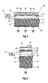
- Fig. 1 is a fragmentary, transverse sectional view of an acoustic ink printer em bodying the present invention;
- Fig. 2 is an enlarged and fragmentary, sagittal sectional view of the printer shown in Fig. 1;
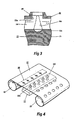
- Fig. 3 is a fragmentary, sagittal sectional view of an acoustic ink printer comprising a modified embodiment of the present invention, and
- Fig. 4 is a schematic view of another embodiment of the invention.
- Turning now to the drawings, and at this point especially to Fig. 1, it will be seen that there is an acoustic ink printer 10 (shown only in relevant part) having a
printhead 11 comprising an array ofacoustic focusing lenses 12a-12i for radiating thefree surface 13 of a pool ofliquid ink 14 with focusedacoustic beams 16a-16i, respectively. As shown, thelenses 12a-12i are acoustically coupled directly to theink 14, but it will be understood that they could be coupled to it via one or more intermediate, liquid or solid, acoustic coupling media (not shown). - The
lenses 12a-12i are defined by more or less identical, small spherical depressions or indentations that are formed on spaced-apart centers in a face (e. g., the upper face) of asubstrate 21 which is composed of a material having a much higher speed of sound than theink 14. For example, when ordinary water-based or oil-based inks are employed, this criterion can be satisfied by fabricating thelens substrate 21 from materials such as silicon, silicon carbide, silicon nitride, alumna, sapphire, fused quartz and certain glasses. - During operation, the
lenses 12a-12i are independently acoustically illuminated from the rear by respective acoustic waves which are coupled into thesubstrate 21 by a suitable acoustic generator, such as an RF-exciied, spatially-addressable,piezoelectric transducer 22. As will be appreciated, thelenses 12a-12i may be axially aligned on equidistant centers to provide a linear array of droplet ejectors, or they may be arranged in a plurality of rows on staggered centers to provide a staggered droplet ejector array. Indeed, it will become evident that the present invention can be used to advantage with acoustic printheads having one or several droplet ejectors in various geometric configurations. - As previously pointed out, printing is performed by modulating the radiation pressure which each of the
acoustic beams 16a-16i exerts against thefree ink surface 13, whereby individual droplets ofink 25 are ejected from thefree surface 13 on demand at a sufficient speed to cause them to deposit in an image configuration on anearby record medium 26. For example, as schematicaliy illustrated, when a spatially-addressablepiezoelectric transducer 22 is employed for acoustically illuminating thelenses 12a-12i, its RF excitation may be pulse-width modulated on a lens-by-lens basis to modulate the radiation pressures of thebeams 16a-16i. Typically, theprinthead 11 is configured and/or is translated transversely with respect to therecord medium 26 to address all pixel positions across the full width of the image field. Consequently, therecord medium 26 generally is longitudinally advanced with respect to theprinthead 11, as indicated in Fig. 2 by thearrow 28. - In accordance with the present invention, the
free ink surface 13 is maintained in intimate contact with the inner face of a perforated,planar membrane 32, which is supported (by means not shown) in the focal plane of thelenses 12a-12i in parallel alignment with thelens substrate 21. A plurality of substantially-uniform perforations orapertures 33a-33i extend through themembrane 32 on centers that are aligned with one after another of the pixel positions along the transverse dimension of an image field, thereby enabling theprinthead 11 to address all of the pixel positions across the full page width of the image field. The droplets ofink 25 are ejected from thefree ink surface 13 more or less centrally of one or more of theapertures 33a-33i, but the aperture diameters are substantially larger than the waist diameters of the focusedacoustic beams 16a-16i, thereby precluding them from having any significant effect on the size of thedroplets 25. - As a general rule, there is substantially the same capillary attraction between the
ink 14 and the sidewalls of each of theapertures 33a-33i, so the intimate contact of theink 14 with the inner face of themembrane 32, together with the uniformity of theapertures 33a-33i, causes ink menisci to extend across each of theapertures 33a-33i at essentially the same level. Furthermore, during operation, a substantially constant bias pressure is applied to theink 14, such as by anexternal pressure controller 36, thereby maintaining all of these menisci at an essentially constant level. As shown in Fig. 2, this bias pressure may be increased or decreased while theprinter 10 is being readied for operation to increase or decrease the level of the ink menisci within theapertures 33a-33i, as indicated generally at 41-43, thereby permitting the menisci (i. e., the portions of thefree ink surface 13 from which theink droplets 25 are ejected) to be more precisely positioned in the focal plane of thelenses 12a-12i. - Turning to Fig. 3, in keeping with one of the more detailed features of this invention, the spatial stability of the ink menisci within the
apertures 33a-33i may be improved by configuring the outer face of themembrane 32 so that it has elevated,narrow mesas 45 extending outwardly from theapertures 33a-33i. Ink, dust and other debris may tend to fall on the outer face of themembrane 32 during operation, so the sides of these mesa-like structures 45 are sloped downwardly for deflecting much of debris away from theapertures 33a-33i, thereby reducing the accumulation of debris in the immediate proximity of theapertures 33a-33i. For example, themesas 45 may be annular for providing dedicated anti-debris protection for each of theapertures 33a-33i. - Typically, the
membrane 32 is metallic, such as of brass or beryllium copper shimstock, and theapertures 33a-33i are precisely machined in it, such as by chemical etching, Plastics membranes are, however, a conceivable alternative. As will be understood, aplastics membrane 51 could be perforated while it is being fabricated. Alternatively, it might be perforated in situ, either by heat or by acoustic energy. With that in mind, as schematically shown in Fig. 4, there is aplastics membrane 51 which is stripped off afeed roll 52 on one side of theprinthead 11 and collected by a take-up roll 54 on the opposite side of theprinthead 11. Consequently, whenever one section of themembrane 51 has served its useful life, as determined either by subjectively examining it or in accordance with a predetermined replacement schedule, a fresh section of themembrane 51 can be advanced into position to replace it. As will be appreciated, one of the advantages of advancing themembrane 51 across the free ink surface 13 (Fig. 1) from time-to-time is that much of the dust and other debris that may have accumulated on the menisci within theapertures 33a-33i is dragged away from theprinthead 11 as themembrane 51 is moved. - If desired, an array of
heating elements 55 may be employed for perforating the fresh section of themembrane 51 as it is being moved into alignment with the printhead 1. Or, theprinthead 11 may be employed to perforate the fresh section of themembrane 51 acoustically after it has been moved into position, such as by driving the droplet ejectors at a subharmonic of the RF frequency that is employed for printing. It will be appreciated that the present invention provides reliable and relatively inexpensive methods and means for maintaining the free ink surface of an acoustic ink printer essentially at an optimum level. Pre-perforated metallic membranes currently are favored for carrying out the present invention, but membranes composed of other materials, such as plastics, as well as membranes which are perforated in situ, are possible alternatives.
Claims (7)
Applications Claiming Priority (2)
| Application Number | Priority Date | Filing Date | Title |
|---|---|---|---|
| US358752 | 1989-05-30 | ||
| US07/358,752 US5028937A (en) | 1989-05-30 | 1989-05-30 | Perforated membranes for liquid contronlin acoustic ink printing |
Publications (3)
| Publication Number | Publication Date |
|---|---|
| EP0400955A2 true EP0400955A2 (en) | 1990-12-05 |
| EP0400955A3 EP0400955A3 (en) | 1991-01-30 |
| EP0400955B1 EP0400955B1 (en) | 1993-12-22 |
Family
ID=23410895
Family Applications (1)
| Application Number | Title | Priority Date | Filing Date |
|---|---|---|---|
| EP90305805A Expired - Lifetime EP0400955B1 (en) | 1989-05-30 | 1990-05-29 | Acoustic ink printing |
Country Status (5)
| Country | Link |
|---|---|
| US (1) | US5028937A (en) |
| EP (1) | EP0400955B1 (en) |
| JP (1) | JPH06102377B2 (en) |
| CA (1) | CA2014660C (en) |
| DE (1) | DE69005362T2 (en) |
Cited By (11)
| Publication number | Priority date | Publication date | Assignee | Title |
|---|---|---|---|---|
| EP0493102A1 (en) * | 1990-12-26 | 1992-07-01 | Xerox Corporation | Acoustic ink printing |
| EP0495623A1 (en) * | 1991-01-14 | 1992-07-22 | Xerox Corporation | Acoustic ink printheads |
| WO1996032279A1 (en) * | 1995-04-12 | 1996-10-17 | Eastman Kodak Company | A liquid ink printing apparatus and system |
| WO1996032277A1 (en) * | 1995-04-12 | 1996-10-17 | Eastman Kodak Company | Coincident drop selection, drop separation printing method and system |
| WO1996033071A1 (en) * | 1995-04-21 | 1996-10-24 | Sergei Nikolaevich Maximovsky | Ink-jet printing method and an ink-jet printing head |
| US5856836A (en) * | 1995-04-12 | 1999-01-05 | Eastman Kodak Company | Coincident drop selection, drop separation printing method and system |
| US5880759A (en) * | 1995-04-12 | 1999-03-09 | Eastman Kodak Company | Liquid ink printing apparatus and system |
| WO2001078985A1 (en) * | 2000-04-13 | 2001-10-25 | Sergei Nikolaevich Maximovsky | Ink-jet printing method and a printing device for carrying out said method |
| WO2001081089A1 (en) * | 2000-04-26 | 2001-11-01 | Sergei Nikolaevich Maximovsky | Method for ink-jet printing and printing device for carrying out said method |
| WO2002036348A2 (en) * | 2000-10-30 | 2002-05-10 | Sergei Nikolaevich Maximovsky | Ink-jet printing method and a printer for carrying out said method |
| EP1494809A2 (en) * | 2002-03-28 | 2005-01-12 | Picoliter Inc. | Use of immiscible fluids in droplet ejection through application of focused acoustic energy |
Families Citing this family (52)
| Publication number | Priority date | Publication date | Assignee | Title |
|---|---|---|---|---|
| US5392064A (en) * | 1991-12-19 | 1995-02-21 | Xerox Corporation | Liquid level control structure |
| DE69218375T2 (en) * | 1991-12-27 | 1997-08-07 | Xerox Corp | Surface wave scattering by means of non-retroreflective opening configurations for acoustic color printers |
| US5450107A (en) * | 1991-12-27 | 1995-09-12 | Xerox Corporation | Surface ripple wave suppression by anti-reflection in apertured free ink surface level controllers for acoustic ink printers |
| DE69214418T2 (en) * | 1991-12-30 | 1997-03-06 | Xerox Corp | Acoustic ink print head with a perforated element and an ink flow |
| JP3419822B2 (en) * | 1992-05-29 | 2003-06-23 | ゼロックス・コーポレーション | Capping structure and droplet ejector |
| US5287126A (en) * | 1992-06-04 | 1994-02-15 | Xerox Corporation | Vacuum cleaner for acoustic ink printing |
| US5354419A (en) * | 1992-08-07 | 1994-10-11 | Xerox Corporation | Anisotropically etched liquid level control structure |
| US5389956A (en) * | 1992-08-18 | 1995-02-14 | Xerox Corporation | Techniques for improving droplet uniformity in acoustic ink printing |
| US5216451A (en) * | 1992-12-27 | 1993-06-01 | Xerox Corporation | Surface ripple wave diffusion in apertured free ink surface level controllers for acoustic ink printers |
| US5428381A (en) * | 1993-07-30 | 1995-06-27 | Xerox Corporation | Capping structure |
| US5565113A (en) * | 1994-05-18 | 1996-10-15 | Xerox Corporation | Lithographically defined ejection units |
| EP0682988B1 (en) * | 1994-05-18 | 2001-11-14 | Xerox Corporation | Acoustic deposition of material layers |
| EP0692383B1 (en) * | 1994-07-11 | 2005-06-15 | Kabushiki Kaisha Toshiba | Ink jet recording device |
| US5608433A (en) * | 1994-08-25 | 1997-03-04 | Xerox Corporation | Fluid application device and method of operation |
| US5631678A (en) * | 1994-12-05 | 1997-05-20 | Xerox Corporation | Acoustic printheads with optical alignment |
| US5821958A (en) * | 1995-11-13 | 1998-10-13 | Xerox Corporation | Acoustic ink printhead with variable size droplet ejection openings |
| EP0881082A3 (en) | 1997-05-29 | 2000-05-03 | Xerox Corporation | Apparatus and method for forming an image with reduced printhead signature |
| US5938827A (en) * | 1998-02-02 | 1999-08-17 | Xerox Corporation | Ink compositions |
| US6644766B1 (en) | 1998-04-28 | 2003-11-11 | Xerox Corporation | Printing system with phase shift printing to reduce peak power consumption |
| US6217151B1 (en) | 1998-06-18 | 2001-04-17 | Xerox Corporation | Controlling AIP print uniformity by adjusting row electrode area and shape |
| US6210783B1 (en) | 1998-07-17 | 2001-04-03 | Xerox Corporation | Ink jet transparencies |
| US6312121B1 (en) | 1998-09-11 | 2001-11-06 | Xerox Corporation | Ink jet printing process |
| US6364454B1 (en) | 1998-09-30 | 2002-04-02 | Xerox Corporation | Acoustic ink printing method and system for improving uniformity by manipulating nonlinear characteristics in the system |
| US6302524B1 (en) | 1998-10-13 | 2001-10-16 | Xerox Corporation | Liquid level control in an acoustic droplet emitter |
| US6136210A (en) * | 1998-11-02 | 2000-10-24 | Xerox Corporation | Photoetching of acoustic lenses for acoustic ink printing |
| US6318852B1 (en) | 1998-12-30 | 2001-11-20 | Xerox Corporation | Color gamut extension of an ink composition |
| US6161270A (en) * | 1999-01-29 | 2000-12-19 | Eastman Kodak Company | Making printheads using tapecasting |
| US6168746B1 (en) | 1999-02-22 | 2001-01-02 | Eastman Kodak Company | Injection molding of ferroelectric articles |
| US6110265A (en) | 1999-04-27 | 2000-08-29 | Xerox Corporation | Ink compositions |
| US6595618B1 (en) | 1999-06-28 | 2003-07-22 | Xerox Corporation | Method and apparatus for filling and capping an acoustic ink printhead |
| US6523944B1 (en) | 1999-06-30 | 2003-02-25 | Xerox Corporation | Ink delivery system for acoustic ink printing applications |
| US6254819B1 (en) | 1999-07-16 | 2001-07-03 | Eastman Kodak Company | Forming channel members for ink jet printheads |
| US6199970B1 (en) * | 1999-07-23 | 2001-03-13 | Xerox Corporation | Acoustic ink jet printhead design and method of operation utilizing ink cross-flow |
| US6367909B1 (en) | 1999-11-23 | 2002-04-09 | Xerox Corporation | Method and apparatus for reducing drop placement error in printers |
| US6322187B1 (en) | 2000-01-19 | 2001-11-27 | Xerox Corporation | Method for smoothing appearance of an ink jet print |
| US6350795B1 (en) | 2000-06-07 | 2002-02-26 | Xerox Corporation | Ink compositions |
| US6287373B1 (en) | 2000-06-22 | 2001-09-11 | Xerox Corporation | Ink compositions |
| US6596239B2 (en) * | 2000-12-12 | 2003-07-22 | Edc Biosystems, Inc. | Acoustically mediated fluid transfer methods and uses thereof |
| US7121275B2 (en) * | 2000-12-18 | 2006-10-17 | Xerox Corporation | Method of using focused acoustic waves to deliver a pharmaceutical product |
| US8122880B2 (en) * | 2000-12-18 | 2012-02-28 | Palo Alto Research Center Incorporated | Inhaler that uses focused acoustic waves to deliver a pharmaceutical product |
| US6976639B2 (en) | 2001-10-29 | 2005-12-20 | Edc Biosystems, Inc. | Apparatus and method for droplet steering |
| US6737109B2 (en) | 2001-10-31 | 2004-05-18 | Xerox Corporation | Method of coating an ejector of an ink jet printhead |
| US20030085952A1 (en) * | 2001-11-05 | 2003-05-08 | Williams Roger O | Apparatus and method for controlling the free surface of liquid in a well plate |
| US6925856B1 (en) | 2001-11-07 | 2005-08-09 | Edc Biosystems, Inc. | Non-contact techniques for measuring viscosity and surface tension information of a liquid |
| US7275807B2 (en) * | 2002-11-27 | 2007-10-02 | Edc Biosystems, Inc. | Wave guide with isolated coupling interface |
| US7429359B2 (en) * | 2002-12-19 | 2008-09-30 | Edc Biosystems, Inc. | Source and target management system for high throughput transfer of liquids |
| US7504446B2 (en) * | 2003-10-09 | 2009-03-17 | Xerox Corporation | Aqueous inks containing colored polymers |
| US20090301550A1 (en) * | 2007-12-07 | 2009-12-10 | Sunprint Inc. | Focused acoustic printing of patterned photovoltaic materials |
| US20100184244A1 (en) * | 2009-01-20 | 2010-07-22 | SunPrint, Inc. | Systems and methods for depositing patterned materials for solar panel production |
| WO2017041130A1 (en) * | 2015-09-07 | 2017-03-16 | Monash University | Device and method for droplet ejection |
| DE102019102232A1 (en) * | 2018-01-30 | 2019-08-01 | Ford Motor Company | ULTRASONIC TRANSMITTER WITH ACOUSTIC FOCUSING DEVICE |
| US11400477B2 (en) * | 2018-01-30 | 2022-08-02 | Ford Motor Company | Reversible nozzle in ultrasonic atomizer for clog prevention |
Citations (4)
| Publication number | Priority date | Publication date | Assignee | Title |
|---|---|---|---|---|
| DE2842538A1 (en) * | 1977-10-01 | 1979-04-12 | Canon Kk | METHOD AND DEVICE FOR IMAGE GENERATION |
| US4308547A (en) * | 1978-04-13 | 1981-12-29 | Recognition Equipment Incorporated | Liquid drop emitter |
| EP0107467A2 (en) * | 1982-10-26 | 1984-05-02 | Ing. C. Olivetti & C., S.p.A. | Ink jet printing device |
| US4801953A (en) * | 1987-06-02 | 1989-01-31 | Xerox Corporation | Perforated ink transports for acoustic ink printing |
Family Cites Families (5)
| Publication number | Priority date | Publication date | Assignee | Title |
|---|---|---|---|---|
| US3211088A (en) * | 1962-05-04 | 1965-10-12 | Sperry Rand Corp | Exponential horn printer |
| JPS6097859A (en) * | 1983-11-01 | 1985-05-31 | Fuji Xerox Co Ltd | Ink jet recording head |
| JPS62170350A (en) * | 1986-01-24 | 1987-07-27 | Mitsubishi Electric Corp | Recorder |
| US4719476A (en) * | 1986-04-17 | 1988-01-12 | Xerox Corporation | Spatially addressing capillary wave droplet ejectors and the like |
| US4751529A (en) * | 1986-12-19 | 1988-06-14 | Xerox Corporation | Microlenses for acoustic printing |
-
1989
- 1989-05-30 US US07/358,752 patent/US5028937A/en not_active Expired - Lifetime
-
1990
- 1990-04-17 CA CA002014660A patent/CA2014660C/en not_active Expired - Lifetime
- 1990-05-23 JP JP2133704A patent/JPH06102377B2/en not_active Expired - Fee Related
- 1990-05-29 DE DE69005362T patent/DE69005362T2/en not_active Expired - Fee Related
- 1990-05-29 EP EP90305805A patent/EP0400955B1/en not_active Expired - Lifetime
Patent Citations (4)
| Publication number | Priority date | Publication date | Assignee | Title |
|---|---|---|---|---|
| DE2842538A1 (en) * | 1977-10-01 | 1979-04-12 | Canon Kk | METHOD AND DEVICE FOR IMAGE GENERATION |
| US4308547A (en) * | 1978-04-13 | 1981-12-29 | Recognition Equipment Incorporated | Liquid drop emitter |
| EP0107467A2 (en) * | 1982-10-26 | 1984-05-02 | Ing. C. Olivetti & C., S.p.A. | Ink jet printing device |
| US4801953A (en) * | 1987-06-02 | 1989-01-31 | Xerox Corporation | Perforated ink transports for acoustic ink printing |
Cited By (15)
| Publication number | Priority date | Publication date | Assignee | Title |
|---|---|---|---|---|
| EP0493102A1 (en) * | 1990-12-26 | 1992-07-01 | Xerox Corporation | Acoustic ink printing |
| EP0495623A1 (en) * | 1991-01-14 | 1992-07-22 | Xerox Corporation | Acoustic ink printheads |
| US5880759A (en) * | 1995-04-12 | 1999-03-09 | Eastman Kodak Company | Liquid ink printing apparatus and system |
| WO1996032277A1 (en) * | 1995-04-12 | 1996-10-17 | Eastman Kodak Company | Coincident drop selection, drop separation printing method and system |
| US5856836A (en) * | 1995-04-12 | 1999-01-05 | Eastman Kodak Company | Coincident drop selection, drop separation printing method and system |
| WO1996032279A1 (en) * | 1995-04-12 | 1996-10-17 | Eastman Kodak Company | A liquid ink printing apparatus and system |
| EP0890437A3 (en) * | 1995-04-12 | 1999-07-28 | Eastman Kodak Company | A liquid ink printing apparatus and system |
| WO1996033071A1 (en) * | 1995-04-21 | 1996-10-24 | Sergei Nikolaevich Maximovsky | Ink-jet printing method and an ink-jet printing head |
| US6231162B1 (en) | 1995-04-21 | 2001-05-15 | Maximovsky Sergei Nikolaevich | Ink-jet printing method and an ink-jet printing head |
| WO2001078985A1 (en) * | 2000-04-13 | 2001-10-25 | Sergei Nikolaevich Maximovsky | Ink-jet printing method and a printing device for carrying out said method |
| WO2001081089A1 (en) * | 2000-04-26 | 2001-11-01 | Sergei Nikolaevich Maximovsky | Method for ink-jet printing and printing device for carrying out said method |
| WO2002036348A2 (en) * | 2000-10-30 | 2002-05-10 | Sergei Nikolaevich Maximovsky | Ink-jet printing method and a printer for carrying out said method |
| WO2002036348A3 (en) * | 2000-10-30 | 2002-10-24 | Sergei Nikolaevich Maximovsky | Ink-jet printing method and a printer for carrying out said method |
| EP1494809A2 (en) * | 2002-03-28 | 2005-01-12 | Picoliter Inc. | Use of immiscible fluids in droplet ejection through application of focused acoustic energy |
| EP1494809A4 (en) * | 2002-03-28 | 2010-11-03 | Picoliter Inc | Use of immiscible fluids in droplet ejection through application of focused acoustic energy |
Also Published As
| Publication number | Publication date |
|---|---|
| EP0400955A3 (en) | 1991-01-30 |
| CA2014660A1 (en) | 1990-11-30 |
| EP0400955B1 (en) | 1993-12-22 |
| US5028937A (en) | 1991-07-02 |
| DE69005362D1 (en) | 1994-02-03 |
| CA2014660C (en) | 1996-01-09 |
| JPH06102377B2 (en) | 1994-12-14 |
| DE69005362T2 (en) | 1994-05-26 |
| JPH0349958A (en) | 1991-03-04 |
Similar Documents
| Publication | Publication Date | Title |
|---|---|---|
| EP0400955B1 (en) | Acoustic ink printing | |
| US5111220A (en) | Fabrication of integrated acoustic ink printhead with liquid level control and device thereof | |
| US5121141A (en) | Acoustic ink printhead with integrated liquid level control layer | |
| EP0272899B1 (en) | Acoustic printheads | |
| US4751529A (en) | Microlenses for acoustic printing | |
| US5428381A (en) | Capping structure | |
| JP3151312B2 (en) | Liquid level control structure and method of manufacturing the same | |
| JPS63166545A (en) | Spot-size variable acoustic printer | |
| US6336707B1 (en) | Recording element and recording device | |
| JP2001191537A (en) | Continuous ink jet printer including notch deflector | |
| US6644785B2 (en) | Solid BI-layer structures for use with high viscosity inks in acoustic ink in acoustic ink printing and methods of fabrication | |
| US7829818B2 (en) | Ink jet head nozzle plate manufacturing method, ink jet head nozzle plate manufacturing apparatus, ink jet head nozzle plate, ink jet head, and ink jet recording apparatus | |
| EP0272092B1 (en) | Acoustic printers | |
| US20020057304A1 (en) | Drive method for ink jet head | |
| EP0549243B1 (en) | Surface ripple wave diffusion by non-retroreflective aperture configurations for acoustic ink printers | |
| JP4529621B2 (en) | Liquid ejecting apparatus and method for manufacturing liquid ejecting head | |
| JP2644407B2 (en) | Nozzleless droplet ejection system | |
| JP3563887B2 (en) | Manufacturing method of liquid jet recording head | |
| JPH10328594A (en) | Liquid drop forming device and image forming method |
Legal Events
| Date | Code | Title | Description |
|---|---|---|---|
| PUAI | Public reference made under article 153(3) epc to a published international application that has entered the european phase |
Free format text: ORIGINAL CODE: 0009012 |
|
| AK | Designated contracting states |
Kind code of ref document: A2 Designated state(s): DE FR GB |
|
| PUAL | Search report despatched |
Free format text: ORIGINAL CODE: 0009013 |
|
| AK | Designated contracting states |
Kind code of ref document: A3 Designated state(s): DE FR GB |
|
| 17P | Request for examination filed |
Effective date: 19910701 |
|
| 17Q | First examination report despatched |
Effective date: 19930225 |
|
| GRAA | (expected) grant |
Free format text: ORIGINAL CODE: 0009210 |
|
| AK | Designated contracting states |
Kind code of ref document: B1 Designated state(s): DE FR GB |
|
| REF | Corresponds to: |
Ref document number: 69005362 Country of ref document: DE Date of ref document: 19940203 |
|
| ET | Fr: translation filed | ||
| PLBE | No opposition filed within time limit |
Free format text: ORIGINAL CODE: 0009261 |
|
| STAA | Information on the status of an ep patent application or granted ep patent |
Free format text: STATUS: NO OPPOSITION FILED WITHIN TIME LIMIT |
|
| 26N | No opposition filed | ||
| REG | Reference to a national code |
Ref country code: GB Ref legal event code: IF02 |
|
| PGFP | Annual fee paid to national office [announced via postgrant information from national office to epo] |
Ref country code: FR Payment date: 20050511 Year of fee payment: 16 |
|
| PGFP | Annual fee paid to national office [announced via postgrant information from national office to epo] |
Ref country code: GB Payment date: 20050525 Year of fee payment: 16 |
|
| PGFP | Annual fee paid to national office [announced via postgrant information from national office to epo] |
Ref country code: DE Payment date: 20050526 Year of fee payment: 16 |
|
| PG25 | Lapsed in a contracting state [announced via postgrant information from national office to epo] |
Ref country code: GB Free format text: LAPSE BECAUSE OF NON-PAYMENT OF DUE FEES Effective date: 20060529 |
|
| PG25 | Lapsed in a contracting state [announced via postgrant information from national office to epo] |
Ref country code: DE Free format text: LAPSE BECAUSE OF NON-PAYMENT OF DUE FEES Effective date: 20061201 |
|
| GBPC | Gb: european patent ceased through non-payment of renewal fee |
Effective date: 20060529 |
|
| REG | Reference to a national code |
Ref country code: FR Ref legal event code: ST Effective date: 20070131 |
|
| PG25 | Lapsed in a contracting state [announced via postgrant information from national office to epo] |
Ref country code: FR Free format text: LAPSE BECAUSE OF NON-PAYMENT OF DUE FEES Effective date: 20060531 |