JP4529621B2 - Liquid ejecting apparatus and method for manufacturing liquid ejecting head - Google Patents
Liquid ejecting apparatus and method for manufacturing liquid ejecting head Download PDFInfo
- Publication number
- JP4529621B2 JP4529621B2 JP2004283154A JP2004283154A JP4529621B2 JP 4529621 B2 JP4529621 B2 JP 4529621B2 JP 2004283154 A JP2004283154 A JP 2004283154A JP 2004283154 A JP2004283154 A JP 2004283154A JP 4529621 B2 JP4529621 B2 JP 4529621B2
- Authority
- JP
- Japan
- Prior art keywords
- liquid
- nozzle
- repellent
- nozzle opening
- coating layer
- Prior art date
- Legal status (The legal status is an assumption and is not a legal conclusion. Google has not performed a legal analysis and makes no representation as to the accuracy of the status listed.)
- Expired - Fee Related
Links
Images


Description
本発明は、複数のノズル開口が開設されたノズル形成部材を有する液体噴射ヘッドを備えた液体噴射装置、及び、液体噴射ヘッドの製造方法に関する。 The present invention relates to a liquid ejecting apparatus having a liquid jet head having a Roh nozzle formation member in which a plurality of nozzle openings are opened, and a method of manufacturing a liquid jet head.
液体噴射装置は、液体を液滴として吐出可能な液体噴射ヘッドを備え、この液体噴射ヘッドから各種の液体を吐出する装置である。この液体噴射装置の代表的なものとして、例えば、液体状のインクをインク滴として吐出するインクジェット記録ヘッド(液体噴射ヘッドの一種:以下、記録ヘッドという)を備え、吐出対象物(記録媒体)としての記録紙の幅方向である主走査方向への記録ヘッドの移動と、主走査方向に直交する副走査方向への記録紙の搬送とを繰り返しながら記録ヘッドから液滴を吐出させて記録を行うインクジェット式プリンタ(以下、プリンタという)等の画像記録装置を挙げることができる。 The liquid ejecting apparatus is an apparatus that includes a liquid ejecting head capable of ejecting liquid as droplets and ejects various liquids from the liquid ejecting head. As a typical example of this liquid ejecting apparatus, for example, an ink jet recording head (a kind of liquid ejecting head: hereinafter referred to as a recording head) that ejects liquid ink as ink droplets is provided, and an ejection target (recording medium) is used. Recording is performed by ejecting droplets from the recording head while repeating the movement of the recording head in the main scanning direction, which is the width direction of the recording paper, and the conveyance of the recording paper in the sub-scanning direction orthogonal to the main scanning direction. An image recording apparatus such as an ink jet printer (hereinafter referred to as a printer) can be used.
上記記録ヘッドは、複数のノズル開口を列設してなるノズル列が形成されたノズル形成部材としてのノズルプレート、共通液体室(リザーバ)から圧力室を経てノズル開口に至る一連の流路を形成した流路形成基板、及び、圧力室の容積を変動させ得る圧力発生素子等を積層した状態で備え、圧力発生素子の作動により圧力室内のインクに圧力変動を励起させて液体状のインクをインク滴としてノズル開口から吐出可能に構成されている。 The recording head forms a nozzle plate as a nozzle forming member in which a nozzle row is formed by arranging a plurality of nozzle openings, and a series of flow paths from a common liquid chamber (reservoir) to a nozzle opening through a pressure chamber. The flow path forming substrate and the pressure generating element capable of changing the volume of the pressure chamber are stacked, and the pressure generating element is actuated to excite the pressure fluctuation in the ink in the pressure chamber. The droplets are configured to be ejected from the nozzle opening.
ところで、このノズル開口の周囲のインクの濡れの状態によっては、吐出したインク滴に飛行曲がりが生じることがある。インク滴の飛行曲がりが生じると、吐出対象物である記録紙上においてインク滴が目標とする着弾位置(以下、目標着弾位置という。)からずれた位置に着弾してしまい、その結果、バンディング(筋状のノイズ)や色斑が発生したり、粒状感が大きくなる等、記録画像の画質の低下を招いてしまう。 By the way, depending on the wet state of the ink around the nozzle opening, the flighted ink droplet may be bent. When the flying bend of the ink droplet occurs, the ink droplet lands on a recording paper that is an ejection target at a position shifted from a target landing position (hereinafter referred to as a target landing position). Noise) and color spots, and the graininess increases, resulting in a deterioration in the image quality of the recorded image.
このようなインク滴の飛行曲がりを防止するために、この種のノズルプレートの表面(インク滴吐出側の面)には、撥液被膜層が形成されており、この撥液被膜層によってノズル開口の周囲のインクの濡れを可及的に抑えるようにしている。
ところが、この撥液被膜層を形成したときに撥液被膜層がノズル開口の内部(内周面)に不均一に入り込んでしまうことがあり、この不均一に入り込んだ撥液被膜層に起因してインク滴の飛行曲がりが生じる虞がある。
そのため、ノズル開口の内部に入り込まないようにノズルプレートの表面のみに撥液被膜層を形成する方法も提案されている(例えば、特許文献1参照)。
However, when this liquid-repellent coating layer is formed, the liquid-repellent coating layer may enter the inside (inner peripheral surface) of the nozzle opening non-uniformly, and this is caused by the non-uniformly entering liquid-repellent coating layer. Ink droplets may be bent.
Therefore, a method of forming a liquid repellent coating layer only on the surface of the nozzle plate so as not to enter the inside of the nozzle opening has been proposed (see, for example, Patent Document 1).
しかしながら、上記特許文献1に開示されている方法は、比較的多くの工程を経る必要があり、量産には不利となるという問題があった。
また、ノズル開口の内部に入り込まないようにノズルプレートの表面のみに撥液被膜層を形成できたとしても、ノズル開口は数10μmという極めて微細な孔であるので、ノズル開口周囲において濡れの状態を均一にするには限界があり、依然として飛行曲がりは生じてしまう。
However, the method disclosed in
Even if the liquid repellent film layer can be formed only on the surface of the nozzle plate so as not to enter the inside of the nozzle opening, the nozzle opening is a very fine hole of several tens of μm. There is a limit to making it uniform, and flight bending still occurs.
本発明はこのような問題に鑑みてなされたもので、その目的は、ノズル開口から吐出される液滴の吐出方向を比較的簡単な加工で調整可能な液体噴射装置、及び、液体噴射ヘッドの製造方法を提供することにある。 The present invention has been made in view of such problems, and an object of the invention is to provide a liquid ejecting apparatus capable of adjusting the ejection direction of liquid droplets ejected from a nozzle opening by relatively simple processing, and a liquid ejecting head. It is to provide a manufacturing method.
本発明は、上記目的を達成するために提案されたものであり、複数のノズル開口を列設してなるノズル形成面の表面を撥液被膜層で被覆したノズル形成部材を有し、圧力発生素子の作動によって前記ノズル開口から液滴を吐出して吐出対象物上にドットを形成可能な液体噴射ヘッドを備えた液体噴射装置であって、
ノズル開口の周囲の撥液被膜層において、前記ノズル開口から離間した位置の一部に、前記ノズル開口との間に撥液被膜層を残した状態で非撥液部を形成し、
前記非撥液部の形成位置を、前記ノズル開口から吐出される液滴に対して前記非撥液部に付着した液体が引力を発揮することが可能な範囲内に設定し、
前記非撥液部に付着する液体の引力により、当該ノズル開口から吐出される液滴の吐出方向を調整可能としたことを特徴とする。
The present invention has been proposed to achieve the above object, and has a nozzle forming member in which a surface of a nozzle forming surface formed by arranging a plurality of nozzle openings is covered with a liquid repellent coating layer, and generates pressure. A liquid ejecting apparatus including a liquid ejecting head capable of ejecting a droplet from the nozzle opening by an operation of an element to form a dot on an ejection target ,
In the liquid-repellent coating layer around the nozzle opening, a non-liquid-repellent portion is formed in a part of the position spaced from the nozzle opening while leaving the liquid-repellent coating layer between the nozzle opening ,
The formation position of the non-liquid repellent part is set within a range in which the liquid attached to the non-liquid repellent part can exert an attractive force with respect to the liquid droplets discharged from the nozzle opening,
The discharge direction of the liquid droplets discharged from the nozzle opening can be adjusted by the attractive force of the liquid adhering to the non-liquid repellent portion .
上記構成によれば、ノズル開口の周囲の撥液被膜層において、ノズル開口から離間した位置の一部に、ノズル開口との間に撥液被膜層を残した状態で非撥液部を形成し、非撥液部の形成位置を、ノズル開口から吐出される液滴に対して非撥液部に付着した液体が引力を発揮することが可能な範囲内に設定し、非撥液部に付着する液体の引力により、ノズル開口から吐出される液滴の吐出方向を調整可能としたので、高精度な加工技術を要することなく簡単な構成で、液滴を然るべき方向に吐出させることができる。
また、上記構成によれば、非撥液部の形成位置に応じて液滴の吐出方向を任意に調整することが可能である。
そして、液滴を然るべき方向に吐出させることが可能であるので、液滴の吐出方向に関し、装置の用途や必要性に応じてより最適な吐出方向が得られる液体噴射装置を提供することが可能となる。
なお、「ノズル開口の周囲」とは、非撥液部に付着する液体が、ノズル開口から吐出される液滴に対して引力(例えば、クーロン力や表面張力)を発揮することが可能な、非撥液部の形成位置の範囲を示す概念である。
According to the above configuration, in the liquid repellent coating layer around the nozzle opening , the non-liquid repellent portion is formed in a part of the position spaced from the nozzle opening while leaving the liquid repellent coating layer between the nozzle opening. The position where the non-liquid-repellent part is formed is set within a range in which the liquid adhering to the non-liquid-repellent part can exert attraction with respect to the liquid droplets discharged from the nozzle opening, and adheres to the non-liquid-repellent part Since the direction of the liquid droplets discharged from the nozzle openings can be adjusted by the attractive force of the liquid to be discharged, the liquid droplets can be discharged in the appropriate direction with a simple configuration without requiring a highly accurate processing technique.
Moreover, according to the said structure, it is possible to adjust arbitrarily the discharge direction of a droplet according to the formation position of a non-liquid-repellent part.
Since the liquid droplets can be discharged in an appropriate direction, it is possible to provide a liquid ejecting apparatus that can obtain a more optimal discharge direction according to the use and necessity of the apparatus regarding the liquid discharge direction. It becomes.
Note that “around the nozzle opening” means that the liquid adhering to the non-liquid-repellent part can exert an attractive force (for example, Coulomb force or surface tension) on the liquid droplets discharged from the nozzle opening. It is a concept showing the range of the formation position of the non-liquid repellent part .
上記構成では、前記非撥液部を、前記ノズル開口と非撥液部との間に撥液被膜層を残した状態で形成している。 In the above configuration , the non-liquid-repellent part is formed in a state where a liquid-repellent coating layer is left between the nozzle opening and the non-liquid-repellent part .
この構成によれば、ノズル開口と非撥液部との間に撥液被膜層を残して非撥液部を形成するので、ノズル開口の開口周縁に連続させた状態で非撥液部を形成するといった高い精度が求められる加工を行う必要が無い。
また、この構成によれば、非撥液部が、ノズル開口の周縁(エッジ)の形状のばらつきの影響を抑えることができ、液滴の吐出方向を安定して調整することが可能となる。これにより、ノズル形成部材の品質をより安定させることが可能となる。
According to this configuration, the non-liquid-repellent part is formed by leaving the liquid-repellent coating layer between the nozzle opening and the non-liquid-repellent part. Therefore, the non-liquid-repellent part is formed in a state of being continuous with the peripheral edge of the nozzle opening. There is no need to perform processing that requires high accuracy.
In addition, according to this configuration, the non-liquid repellent portion can suppress the influence of the variation in the shape of the peripheral edge (edge) of the nozzle opening, and the droplet ejection direction can be stably adjusted. Thereby, the quality of the nozzle forming member can be further stabilized.
また、本発明の液体噴射ヘッドの製造方法は、複数のノズル開口を列設してなるノズル形成面を備え、該ノズル形成面の表面は撥液被膜層が形成されており、圧力発生素子の作動によってノズル開口から液滴を吐出して吐出対象物上にドットを形成可能な液体噴射ヘッドの製造方法であって、
前記液体噴射ヘッドの各ノズル開口から吐出される液滴の目標としている着弾位置である目標着弾位置からのズレを検査するアライメント検査工程と、
前記アライメント検査工程の検査結果に応じて、ノズル開口の周囲の撥液被膜層の一部に非撥液部を形成する非撥液部形成工程とを含み、
前記非撥液部に付着する液体の引力により、吐出する液滴の目標着弾位置からのズレを修正することを特徴とする。
The method of manufacturing a liquid jet head according to the present invention includes a nozzle forming surface in which a plurality of nozzle openings are arranged, and a liquid repellent coating layer is formed on the surface of the nozzle forming surface. A method of manufacturing a liquid jet head capable of forming a dot on a discharge target by discharging droplets from a nozzle opening by operation,
An alignment inspection step for inspecting a deviation from a target landing position which is a target landing position of a droplet discharged from each nozzle opening of the liquid jet head;
A non-liquid-repellent part forming step of forming a non-liquid-repellent part on a part of the liquid-repellent film layer around the nozzle opening according to the inspection result of the alignment inspection process,
The deviation from the target landing position of the ejected droplet is corrected by the attractive force of the liquid adhering to the non-liquid repellent portion.
上記製造方法によれば、アライメント検査工程の検査結果に応じて、ノズル開口の周囲の撥液被膜層の一部に非撥液部を形成し、この非撥液部に付着する液体の引力により、吐出する液滴の目標着弾位置からのズレを修正するので、従来、液滴の実際の着弾位置が目標着弾位置からずれていることを原因として不良品としていた液体噴射ヘッドについても、良品とすることができる。したがって、歩留りを向上させることができる。
また、各液体噴射ヘッド毎にアライメント検査工程を行い、その結果に基づいて非撥液部を形成するので、圧力発生素子等のヘッド構成部材の個体差の影響を排除することができる。これにより、液体噴射ヘッドの個体差に関係なく、液滴を然るべき方向に液滴を吐出させることが可能となる。
According to the above manufacturing method, based on the detection result of the alignment inspection process, the liquid non-repellent part is formed in a portion of the liquid repellent coating layer around the nozzle openings, the attraction of the liquid adhering to the non-lyophobic area Since the deviation from the target landing position of the ejected droplet is corrected, the liquid jet head that has been regarded as defective due to the fact that the actual landing position of the droplet has deviated from the target landing position can be can do. Therefore, the yield can be improved.
In addition, the alignment inspection process is performed for each liquid ejecting head, and the non-liquid-repellent portion is formed based on the result, so that it is possible to eliminate the influence of individual differences in head constituent members such as pressure generating elements. Accordingly, it is possible to eject the droplets in the appropriate direction regardless of the individual difference of the liquid ejecting heads.
以下、本発明を実施するための最良の形態を、添付図面等を参照して説明する。なお、以下に述べる実施の形態では、本発明の好適な具体例として種々の限定がされているが、本発明の範囲は、以下の説明において特に本発明を限定する旨の記載がない限り、これらの態様に限られるものではない。また、以下の説明は、代表的な液体噴射装置であるインクジェット式記録装置(以下、単にプリンタという)を例に挙げて行う。 The best mode for carrying out the present invention will be described below with reference to the accompanying drawings. In the embodiments described below, various limitations are made as preferred specific examples of the present invention. However, the scope of the present invention is not limited to the following description unless otherwise specified. However, the present invention is not limited to these embodiments. The following description will be given by taking an ink jet recording apparatus (hereinafter simply referred to as a printer) as a typical liquid ejecting apparatus as an example.
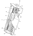
図1はプリンタ1の構成を示す斜視図である。このプリンタ1は、記録ヘッド2が取り付けられると共に、インクカートリッジ3が着脱可能に取り付けられるキャリッジ4と、記録ヘッド2の下方に配設されたプラテン5と、キャリッジ4(記録ヘッド2)を吐出対象物の一種としての記録紙6の紙幅方向、即ち、主走査方向に往復移動させるキャリッジ移動機構7と、主走査方向に直交する方向である副走査方向に記録紙6を搬送する紙送り機構8とを備えて概略構成されている。
FIG. 1 is a perspective view showing the configuration of the
キャリッジ4は、主走査方向に架設されたガイドロッド9に軸支された状態で取り付けられており、キャリッジ移動機構7の作動により、ガイドロッド9に沿って主走査方向に移動するように構成されている。キャリッジ4の主走査方向の位置は、リニアエンコーダ10によって検出され、その検出信号、即ち、エンコーダパルスがプリンタコントローラの制御部(図示せず)に送信される。これにより、制御部はこのリニアエンコーダ10からのエンコーダパルスに基づいてキャリッジ4(記録ヘッド2)の走査位置を認識しながら、記録ヘッド2による記録動作(吐出動作)等を制御することができる。
The
キャリッジ4の移動範囲内における記録領域よりも外側(図1における右側)の端部領域には、走査の基点となるホームポジションが設定されている。本実施形態におけるホームポジションには、記録ヘッド2のノズル形成部材(ノズルプレート21:図2参照)を封止するキャッピング部材11と、ノズル形成面を払拭するためのワイパー部材12とが配置されている。そして、プリンタ1は、このホームポジションから反対側の端部へ向けてキャリッジ4(記録ヘッド2)が移動する往動時と、反対側の端部からホームポジション側にキャリッジ4が戻る復動時との双方向で記録紙6上に文字や画像等を記録する所謂双方向記録が可能に構成されている。
A home position serving as a scanning base point is set in an end area outside the recording area within the moving range of the carriage 4 (right side in FIG. 1). A
図2は、上記記録ヘッド2の構成を説明する要部断面図である。この記録ヘッド2は、ケース13と、このケース13内に収納される振動子ユニット14と、ケース13の底面(先端面)に接合される流路ユニット15等を備えている。上記のケース13は、例えば、エポキシ系樹脂等の合成樹脂により作製され、その内部には振動子ユニット14を収納するための収納空部16が形成されている。振動子ユニット14は、圧力発生素子の一種として機能する圧電振動子17と、この圧電振動子17が接合される固定板18と、圧電振動子17に駆動信号を供給するためのフレキシブルケーブル19とを備えている。圧電振動子17は、圧電体層と電極層とを交互に積層した圧電板を櫛歯状に切り分けることで作製された積層型であって、積層方向に直交する方向に伸縮可能な縦振動モードの圧電振動子である。
FIG. 2 is a cross-sectional view of a main part for explaining the configuration of the
流路ユニット15は、流路形成基板20の一方の面にノズルプレート21を、流路形成基板20の他方の面に弾性板22をそれぞれ接合して構成されている。この流路ユニット15には、リザーバ23と、インク供給口24と、圧力室25と、ノズル連通口26と、ノズル開口27とが形成されている。そして、インク供給口24から圧力室25及びノズル連通口26を経てノズル開口27に至る一連のインク流路が、ノズル開口27毎に対応して形成されている。
The
上記ノズルプレート21は、本発明におけるノズル形成部材の一種であり、ドット形成密度に対応したピッチ(例えば180dpi)で複数のノズル開口27が開設されたステンレス等の金属製の薄いプレートである。このノズルプレート21には、ノズル開口27の列(ノズル列)が複数設けられており、1つのノズル列は、例えば180個のノズル開口27によって構成される。このノズルプレート21の詳細については、図3を用いて後述する。
The
上記弾性板22は、支持板28の表面に弾性体膜29を積層した二重構造である。本実施形態では、金属板の一種であるステンレス板を支持板28とし、この支持板28の表面に樹脂フィルムを弾性体膜29としてラミネートした複合板材を用いて弾性板22を作製している。この弾性板22には、圧力室25の容積を変化させるためのダイヤフラム部30が設けられている。また、この弾性板22には、リザーバ23の一部を封止するコンプライアンス部31が設けられている。
The
上記のダイヤフラム部30は、エッチング加工等によって支持板28を部分的に除去することで作製される。即ち、このダイヤフラム部30は、圧電振動子17の先端面が接合される島部30aと、この島部30aを囲う薄肉弾性部30bとからなる。上記のコンプライアンス部31は、リザーバ23の開口面に対向する領域の支持板28を、ダイヤフラム部30と同様にエッチング加工等によって除去することにより作製され、リザーバ23に貯留された液体の圧力変動を吸収するダンパーとして機能する。
The
そして、上記の島部30aには圧電振動子17の先端面が接合されているので、この圧電振動子17を作動してその自由端部を伸縮させることで、圧力室25の容積を変動させることができる。この容積変動に伴って圧力室25内のインクに圧力変動が生じる。そして、記録ヘッド2は、この圧力変動を利用してノズル開口27からインク滴(液滴の一種)を吐出させるようになっている。
Since the tip surface of the
図3は、本実施形態におけるノズルプレート21の構成を説明する平面図である。このノズルプレート21の基材(以下、ノズルプレート基材33という。)としては、例えばステンレス鋼等の金属製の板材が用いられる。このノズルプレート21には、複数のノズル開口27を副走査方向に列設して1つのノズル列34が形成されている。本実施形態において、上記記録ヘッド2は、互いに異なる色のインク(本発明における液体の一種)を貯留する4つのインクカートリッジ3を装着可能に構成されており、これらの色に対応させて合計4列のノズル列34がノズルプレート21に形成されている。
FIG. 3 is a plan view illustrating the configuration of the
図4は、上記ノズルプレート21におけるノズル開口27の周辺の拡大断面図である。同図に示すように、本実施形態におけるノズル開口27は、圧力室25側からインク滴吐出側に向けてロート状に次第に縮径するテーパー部27aと、このテーパー部27aに連続して形成され、円筒状のストレート部27bとから構成されており、例えばプレス加工によって穿設される。また、ノズルプレート基材33の表面、即ち、インク滴吐出側の面(図4における上側の面)には、撥液被膜層36が形成されている。即ち、ノズルプレート21の表面は、この撥液被膜層36によって被覆されている。この撥液被膜層36としては、例えば、共析メッキが使用される。具体的には、ニッケルイオン等の金属イオンとフッ素樹脂等の撥液性高分子樹脂の粒子を含む電解質溶液中に、電極に接続したノズルプレート21を浸漬し、その表面にメッキを付着させた後、荷重を加えて反りを抑えながら加熱処理することで撥液被膜層36が得られる。
FIG. 4 is an enlarged cross-sectional view around the
この撥液被膜層36は、ノズルプレート21の表面、特に、ノズル開口27の周辺を撥液性にすることで、インクが付着するのを極力防止し、インクの濡れによる吐出インク滴の飛行曲がりを防止するためのものである。しかしながら、この撥液被膜層36を形成したときに撥液被膜層36がノズル開口27の内部(内周面)に不均一に入り込んでしまうことがあり、この不均一に入り込んだ撥液被膜層36に起因してインク滴の飛行曲がりが生じる虞がある。或いは、撥液被膜層36がノズル開口27の周囲に均一に形成されたとしても、記録ヘッド2の各構成部材(振動子ユニット14、流路ユニット15)の寸法精度や組立精度のばらつきによって、インク滴の飛行曲がりが生じることも考えられる。
The liquid
そのため、本実施形態では、記録ヘッド2をプリンタ1に組み付けた状態、即ち、完成品の状態で、記録ヘッド2からインク滴を実際に吐出することで、記録紙6に検査パターンを印刷し、この検査パターンに基づいてインク滴の飛行曲がり(着弾ドットのズレ)を検査するアライメント検査工程を実施する。そして、このアライメント検査工程の結果に応じて、飛行曲がりが生じているノズル開口27について、吐出インク滴が然るべき方向へ飛翔するように調整を行う。インク滴の吐出方向の調整には、ノズルプレート21におけるノズル開口27周囲の撥液被膜層36の一部に非撥液部40(図8参照)を形成し、この非撥液部40に付着するインクの表面張力等の引力を利用する。
Therefore, in the present embodiment, the test pattern is printed on the recording paper 6 by actually ejecting ink droplets from the
以下、アライメント検査工程について説明する。なお、本実施形態においては、ノズル開口27から吐出されるインク滴の吐出方向に関し、主走査方向(ノズル列34とは直交する方向)の調整を行う場合を例示する。
Hereinafter, the alignment inspection process will be described. In the present embodiment, the case of adjusting the main scanning direction (the direction orthogonal to the nozzle row 34) with respect to the ejection direction of the ink droplets ejected from the
本実施形態におけるアライメント検査工程では、例えば、図5に示すような検査パターンが作成される。なお、図5(a)は検査パターンとして記録紙6に記録された縦罫線(一部)を示す図、図5(b)は(a)おける領域Aの拡大図である。図5(a)において、Rで示す4本の縦罫線は、夫々、各ノズル列34に対応している。つまり、ノズル列34を構成している全ノズル開口27からインク滴を一度に吐出して記録紙6上に形成した副走査方向の着弾ドットの列が縦罫線Rとなる。そして、図5(b)において、L1で示す線が、各着弾ドットの副走査方向の目標着弾位置を示す仮想線であり、L2で示す線は、一例として着弾ドットDの副走査方向の実際の着弾位置を示す仮想線である。
In the alignment inspection process in the present embodiment, for example, an inspection pattern as shown in FIG. 5 is created. 5A is a diagram showing (partly) vertical ruled lines recorded on the recording paper 6 as an inspection pattern, and FIG. 5B is an enlarged view of a region A in FIG. In FIG. 5A, the four vertical ruled lines indicated by R correspond to the
上記のような検査パターンを印刷したならば、この検査パターンについてコンピュータ等による解析を行う。即ち、この検査パターンを、例えばスキャナ等の光学的読取手段を用いて読み取り、読み取った画像をコンピュータに出力する。そして、このコンピュータを用いて、読み取った画像における仮想線L1と仮想線L2との間の距離を計測することで、各着弾ドットについて仮想線L1からの着弾ズレ量とその方向(ズレ方向)を取得する。例えば、上記着弾ドットDの場合、図5(b)に示すように、仮想線L1から着弾ズレ量Xだけ右方向にずれているという情報(以下、着弾ズレ情報という)を得る。 When the inspection pattern as described above is printed, the inspection pattern is analyzed by a computer or the like. That is, this inspection pattern is read using an optical reading means such as a scanner, and the read image is output to a computer. Then, by using this computer, by measuring the distance between the virtual line L1 and the virtual line L2 in the read image, the amount of landing deviation from the virtual line L1 and its direction (deviation direction) for each landing dot. get. For example, in the case of the landing dot D, as shown in FIG. 5 (b), information that is shifted to the right by the landing shift amount X from the virtual line L1 (hereinafter referred to as landing shift information) is obtained.
上記アライメント検査工程によって、各ノズル開口27について着弾ズレ情報、即ち、着弾ズレ量とそのズレ方向を取得したならば、取得した着弾ズレ情報に基づいて、ノズル開口27の周囲の撥液被膜層36の一部に、撥液性の低い(親液性を呈する)非撥液部40を形成する非撥液部形成工程を行い、この非撥液部40によって、着弾ドットの着弾ズレが無くなるようにインク滴の吐出方向(飛翔方向)を調整する。この非撥液部40は、撥液被膜層36に所定温度以上の熱を局部的に与え、この部分の撥液被膜層36を除去乃至損傷することで形成することが可能である。本実施形態においては、図6に示すように、電子銃41による電子ビームを用いて非撥液部40を形成する。以下、非撥液部形成工程、及び、非撥液部40による吐出方向の調整についてより詳細に説明する。
If the landing deviation information for each
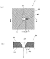
図7は、上記着弾ドットDに対応するノズル開口27の周辺を拡大した図(非撥液部40が形成されていない状態)であり、(a)はノズル開口27周辺の表面側(インク滴吐出側)の平面図、(b)は(a)におけるA−A線断面図である。なお、図7(a)では、上下方向がノズル列方向、即ち、副走査方向となっている。上記のアライメント検査工程において、着弾ドットDに関し、記録紙6上において目標とする着弾位置から着弾ズレ量Xだけ右方向にずれていることが分かった。したがって、ノズル開口27から吐出されるインク滴は、目標とする吐出方向(インク滴が目標着弾位置に着弾する方向/破線で示す方向)に対し、実際には図7において左側にずれた方向(実線で示す方向)に飛翔していることになる。
FIG. 7 is an enlarged view of the periphery of the
そこで、ノズル開口27より吐出されるインク滴の吐出方向を目標とする吐出方向に一致させて、このインク滴を目標着弾位置に着弾させるべく、図8に示すように、非撥液部形成工程において、ノズル開口27の中心軸Cに対してズレ方向と反対側(上記の例では図8において右側)の撥液被膜層36の一部に電子ビームを照射して熱を与え、この部分の撥液被膜層36を除去乃至損傷させて非撥液部40を形成する。
具体的には、電子銃41の加速電圧を5kV〜10kV、エミッション電流を20μAに設定して電子ビームを照射し、例えば、300℃以上の熱を1〜2分間与えることで撥液被膜層36を除去或いは損傷させる。撥液被膜層36を除去乃至損傷して形成された非撥液部40は、下地つまりノズルプレート基材33が現れて撥液性が低下するので、インクが付着し易くなる。即ち、図8(b)に示すように、非撥液部40に付着するインクiの表面張力等を利用して、ノズル開口27から吐出されるインク滴の吐出方向を調整し、これを目標とする吐出方向、即ち、然るべき方向に一致させるのである。
Therefore, as shown in FIG. 8, a non-liquid-repellent part forming step is performed so that the ink droplets ejected from the
Specifically, the accelerating voltage of the
上記電子ビームの照射には既存の装置を利用することができ、非撥液部40を容易に形成することができる。したがって、複雑な装置や処理が不要であり量産に適する。なお、電子ビーム以外にも、例えば、イオンビーム(FIB(Focused Ion Beam))、半導体レーザー、プラズマ処理等、撥液被膜層36に対して所定温度以上の熱を与えることが可能なものを用いることができる。
An existing apparatus can be used for the electron beam irradiation, and the non-liquid-
ここで、本実施形態では、図8(a)に示すように、非撥液部40を、ノズル開口27との間に撥液被膜層36を残した状態でノズル開口27から距離(離隔距離)Zだけ離れた位置に形成している。このように非撥液部40をノズル開口27からある程度離隔させても、この非撥液部40に付着したインクiが吐出インク滴に対し表面張力等の引力を発揮する、つまり、インク滴の吐出方向を調整できることが実験的に分かった。また、ノズル開口27から離隔した位置に非撥液部40を形成した場合、ノズル開口27の内周部に形成するよりも、より効果的に吐出方向の調整ができることが判明した。そして、このように非撥液部40をノズル開口27から離隔させて形成すると、ノズル開口27の周縁(エッジ)の形状のばらつき(歪み)の影響を抑えることができ、液滴の吐出方向を安定して調整することが可能となる。また、ノズル開口27の周縁に連続させた状態で非撥液部40を形成するといった高い精度が求められる加工を行う必要が無い。
なお、ノズル開口27と非撥液部40との離隔距離Zの値は、ノズル開口27のエッジの形状の影響を受けず、且つ、非撥液部40に付着したインクiが吐出インク滴に対し表面張力等の引力を発揮し得る範囲、具体的には、1μm〜8μmであることが望ましい。
Here, in the present embodiment, as shown in FIG. 8A, the
Note that the value of the separation distance Z between the
インク滴の吐出方向の調整量は、上記離隔距離Z、及び、非撥液部40の大きさ(面積)によって定めることができる。これらは、アライメント検査工程で得られた着弾ズレ量に応じて設定する。例えば、上記着弾ドットDの着弾ズレ量Xが5μmである場合、離隔距離Zを2μm、非撥液部40の大きさを約9〜10μm2に設定することで、吐出方向のズレ分を調整することが可能である。なお、非撥液部40の形状に関し、本実施形態においては、方形状の非撥液部40を例示したが、これには限らない。例えば、非撥液部40を、円形等の他の形状にすることもできる。
The adjustment amount of the ink droplet ejection direction can be determined by the separation distance Z and the size (area) of the
また、本実施形態では、ノズル開口27から吐出されるインク滴が、ノズルプレート21の表面に対して垂直に飛翔するように吐出方向を調整する例を示したが、非撥液部40の形成位置を調整することで、インク滴の吐出方向を任意の方向に設定することも可能である。例えば、意図的にインク滴がノズルプレート21の表面に対して斜めに吐出されるように調整することもできる。
In the present embodiment, the example in which the ejection direction is adjusted so that the ink droplets ejected from the
以上のように、ノズル開口27の周囲の撥液被膜層36の一部に非撥液部40を形成し、この非撥液部40により、当該ノズル開口27から吐出されるインク滴の吐出方向を調整するので、高精度な加工技術を要することなく簡単な構成で、然るべき方向に液滴を吐出させることが可能となる。また、アライメント検査工程の検査結果に応じて、ノズル開口27の周囲の撥液被膜層36の一部に非撥液部40を形成し、この非撥液部40により、吐出するインク滴の目標着弾位置からのズレを修正するので、従来、インク滴の実際の着弾位置が目標着弾位置からずれていることを原因として不良品としていた記録ヘッド2についても、良品とすることができ、歩留りを向上させることができる。さらには、記録ヘッド2毎にアライメント検査工程を行い、その結果に基づいて非撥液部40を形成するので、圧電振動子17等のヘッド構成部材の個体差の影響を排除することができる。これにより、構成部材の個体差に関係なく、記録画像の画質の低下の抑えた記録ヘッド2を提供することが可能となる。
As described above, the non-liquid-
次に、本発明の第2の実施形態について説明する。
図9は、本実施形態におけるノズルプレート21´の構成を説明する断面図である。このノズルプレート21´は、図9(a)に示すように、ノズルプレート基材33の表面に、珪素化合物である下地膜44をプラズマ重合によって形成し、この下地膜44の表面にフッ素樹脂等の撥液性高分子を含む撥液被膜層36を形成して構成されている。したがって、上記第1実施形態のようにメッキ処理を行わずに撥液被膜層36を形成することができるので、環境への影響を配慮したノズルプレート21´を製造することができる。
Next, a second embodiment of the present invention will be described.
FIG. 9 is a cross-sectional view illustrating the configuration of the
本実施形態におけるノズルプレート21´に非撥液部40を形成するには、先ず、図9(b)に示すように、撥液被膜層36において非撥液部40を形成する領域以外をマスキング材45によって被覆する。そして、非撥液部40を形成する領域に、紫外線ランプ等を用いて紫外光(UV)を照射する。これにより、この領域の下地膜44と撥液被膜層36のシロキサン結合が破壊されて、図9(c)に示すように、撥液被膜層36の一部を除去することができる。そして、撥液被膜層36を除去して親液性の下地膜44が現れた部分が非撥液部40となる。なお、紫外線を収束可能な装置を用いれば、マスキング材45を使用せずに非撥液部40を形成することも可能である。
In order to form the non-liquid-
このように、本実施形態におけるノズルプレート21´を用いる場合においても、紫外線を照射するという非常に簡単な方法で非撥液部40を形成することができる。なお、他の工程については上記実施形態と同様であるので、その説明は省略する。
Thus, even when the
ところで、本発明は、上記実施形態に限定されるものではなく、特許請求の範囲の記載に基づいて種々の変形が可能である。 By the way, the present invention is not limited to the above embodiment, and various modifications can be made based on the description of the scope of claims.
例えば、ノズル開口27から吐出されるインク滴の吐出方向に関し、上記実施形態においては、アライメント検査工程において縦罫線Rを記録した検査パターンを検査することで、主走査方向(ノズル列34とは直交する方向)の調整を行う場合を例示したが、このアライメント検査工程で横罫線を記録し、これに基づいて副走査方向(ノズル列方向)の調整を行うこともできる。
For example, with respect to the ejection direction of the ink droplets ejected from the
また、上記各実施形態では、電子ビームや紫外線等を照射することで、撥液被膜層36を除去乃至損傷させて非撥液部40を形成する例を示したが、これには限らない。例えば、親液材を付加(塗布)してその部分を非撥液部40としても良い。この親液材としては、例えば、アルミナ、シリカ、酸化チタン、酸化セリウム等の金属の酸化物や窒化物等の親液性化合物の微粒子、アクリル酸やメタクリル酸の単独或いは共重合体、ポリビニルアルコール、ポリビニルピロリドン、ポリアクリルアミドの単独或いは共重合体に代表される親液性高分子が、架橋によって液に不溶となった微粒子等を使用することができる。
In each of the above-described embodiments, an example in which the liquid-
また、ノズル形成部材を備えているものであれば、例示したプリンタには限らず、例えば、液晶ディスプレー等のカラーフィルタの製造に用いられる色材噴射ヘッド、有機EL(Electro Luminescence)ディスプレー、FED(面発光ディスプレー)等の電極形成に用いられる電極材噴射ヘッド、バイオチップ(生物化学素子)の製造に用いられる生体有機物噴射ヘッド等、他の液体噴射ヘッドにも本発明を適用することができる。これにより、用途や必要性に応じてより最適な吐出方向が得られる液体噴射装置を提供することが可能となる。 Further, as long as the nozzle forming member is provided, the printer is not limited to the exemplified printer. For example, a color material ejecting head, an organic EL (Electro Luminescence) display, an FED (FED) used for manufacturing a color filter such as a liquid crystal display. The present invention can also be applied to other liquid ejecting heads such as an electrode material ejecting head used for forming an electrode such as a surface emitting display and a bioorganic matter ejecting head used for manufacturing a biochip (biochemical element). Accordingly, it is possible to provide a liquid ejecting apparatus that can obtain a more optimal ejection direction according to the application and necessity.
1 プリンタ,2 記録ヘッド,3 インクカートリッジ,4 キャリッジ,5 プラテン,6 記録紙,7 キャリッジ移動機構,8 紙送り機構,9 ガイドロッド,10 リニアエンコーダ,11 キャッピング部材,12 ワイパー部材,13 ケース,14 振動子ユニット,15 流路ユニット,16 収納空部,17 圧電振動子,18 固定板,19 フレキシブルケーブル,20 流路形成基板,21 ノズルプレート,22 弾性板,23 リザーバ,24 インク供給口,25 圧力室,26 ノズル連通口,27 ノズル開口,28 支持板,29 弾性体膜,30 ダイヤフラム部,31 コンプライアンス部,33 ノズルプレート基材,34 ノズル列,36 撥液被膜層,40 撥液部,41 電子銃,44 下地膜
DESCRIPTION OF
Claims (2)
ノズル開口の周囲の撥液被膜層において、前記ノズル開口から離間した位置の一部に、前記ノズル開口との間に撥液被膜層を残した状態で非撥液部を形成し、
前記非撥液部の形成位置を、前記ノズル開口から吐出される液滴に対して前記非撥液部に付着した液体が引力を発揮することが可能な範囲内に設定し、
前記非撥液部に付着する液体の引力により、当該ノズル開口から吐出される液滴の吐出方向を調整可能としたことを特徴とする液体噴射装置。 It has a nozzle forming member in which the surface of the nozzle forming surface formed by arranging a plurality of nozzle openings is covered with a liquid repellent coating layer, and the droplets are discharged from the nozzle openings by the operation of the pressure generating element. A liquid ejecting apparatus including a liquid ejecting head capable of forming dots on
In the liquid-repellent coating layer around the nozzle opening, a non-liquid-repellent portion is formed in a part of the position spaced from the nozzle opening while leaving the liquid-repellent coating layer between the nozzle opening ,
The formation position of the non-liquid repellent part is set within a range in which the liquid attached to the non-liquid repellent part can exert an attractive force with respect to the liquid droplets discharged from the nozzle opening,
Wherein the attractive force of the liquid which adheres to the non-lyophobic part, the liquid ejecting apparatus, wherein a discharge direction of liquid droplets discharged from the nozzle opening was adjustable.
前記液体噴射ヘッドの各ノズル開口から吐出される液滴の目標としている着弾位置である目標着弾位置からのズレを検査するアライメント検査工程と、 An alignment inspection step for inspecting a deviation from a target landing position which is a target landing position of a droplet discharged from each nozzle opening of the liquid jet head;
前記アライメント検査工程の検査結果に応じて、ノズル開口の周囲の撥液被膜層の一部に非撥液部を形成する非撥液部形成工程とを含み、 A non-liquid-repellent part forming step of forming a non-liquid-repellent part on a part of the liquid-repellent film layer around the nozzle opening according to the inspection result of the alignment inspection process,
前記非撥液部に付着する液体の引力により、吐出する液滴の目標着弾位置からのズレを修正することを特徴とする液体噴射ヘッドの製造方法。 A method of manufacturing a liquid ejecting head, wherein a deviation from a target landing position of a discharged droplet is corrected by an attractive force of a liquid adhering to the non-liquid repellent portion.
Priority Applications (1)
| Application Number | Priority Date | Filing Date | Title |
|---|---|---|---|
| JP2004283154A JP4529621B2 (en) | 2004-09-29 | 2004-09-29 | Liquid ejecting apparatus and method for manufacturing liquid ejecting head |
Applications Claiming Priority (1)
| Application Number | Priority Date | Filing Date | Title |
|---|---|---|---|
| JP2004283154A JP4529621B2 (en) | 2004-09-29 | 2004-09-29 | Liquid ejecting apparatus and method for manufacturing liquid ejecting head |
Publications (3)
| Publication Number | Publication Date |
|---|---|
| JP2006095792A JP2006095792A (en) | 2006-04-13 |
| JP2006095792A5 JP2006095792A5 (en) | 2007-08-16 |
| JP4529621B2 true JP4529621B2 (en) | 2010-08-25 |
Family
ID=36236071
Family Applications (1)
| Application Number | Title | Priority Date | Filing Date |
|---|---|---|---|
| JP2004283154A Expired - Fee Related JP4529621B2 (en) | 2004-09-29 | 2004-09-29 | Liquid ejecting apparatus and method for manufacturing liquid ejecting head |
Country Status (1)
| Country | Link |
|---|---|
| JP (1) | JP4529621B2 (en) |
Families Citing this family (1)
| Publication number | Priority date | Publication date | Assignee | Title |
|---|---|---|---|---|
| JP6310158B2 (en) * | 2015-08-27 | 2018-04-11 | 富士フイルム株式会社 | Liquid ejection head, liquid ejection apparatus and flight direction control method |
Citations (2)
| Publication number | Priority date | Publication date | Assignee | Title |
|---|---|---|---|---|
| JPH06246921A (en) * | 1993-02-25 | 1994-09-06 | Seiko Epson Corp | Nozzle plate and surface treatment thereof |
| JP2003300323A (en) * | 2002-04-11 | 2003-10-21 | Canon Inc | Ink jet head and its producing method |
-
2004
- 2004-09-29 JP JP2004283154A patent/JP4529621B2/en not_active Expired - Fee Related
Patent Citations (2)
| Publication number | Priority date | Publication date | Assignee | Title |
|---|---|---|---|---|
| JPH06246921A (en) * | 1993-02-25 | 1994-09-06 | Seiko Epson Corp | Nozzle plate and surface treatment thereof |
| JP2003300323A (en) * | 2002-04-11 | 2003-10-21 | Canon Inc | Ink jet head and its producing method |
Also Published As
| Publication number | Publication date |
|---|---|
| JP2006095792A (en) | 2006-04-13 |
Similar Documents
| Publication | Publication Date | Title |
|---|---|---|
| US8012538B2 (en) | Method of manufacturing at least one projecting section of nozzle plate, nozzle plate, inkjet head and image forming apparatus | |
| US20090244173A1 (en) | Nozzle plate, liquid ejection head and image forming apparatus | |
| US20060221161A1 (en) | Image forming apparatus | |
| US10112392B2 (en) | Liquid ejecting head and liquid ejecting apparatus | |
| US20060268074A1 (en) | Liquid ejection head and method of manufacturing same | |
| US7771021B2 (en) | Inkjet head assembly and printing apparatus with ultraviolet emitting unit and method using the same | |
| JP2007144734A (en) | Liquid ejection head, and liquid ejector | |
| US8388087B2 (en) | Liquid ejecting apparatus and method of controlling same | |
| JP4529621B2 (en) | Liquid ejecting apparatus and method for manufacturing liquid ejecting head | |
| US8069564B2 (en) | Alignment jig and alignment apparatus for liquid-jet head and method for producing liquid-jet head | |
| US7829818B2 (en) | Ink jet head nozzle plate manufacturing method, ink jet head nozzle plate manufacturing apparatus, ink jet head nozzle plate, ink jet head, and ink jet recording apparatus | |
| JP2003305851A (en) | Inkjet head and inkjet recorder | |
| JP2005238787A (en) | Ink ejection amount measuring method, and ink ejection amount control method and ink-jet device using the same | |
| JP2000153603A (en) | Delivery ink measuring apparatus | |
| US20060066687A1 (en) | Liquid ejection head, liquid ejection apparatus and image forming apparatus | |
| EP1693204B1 (en) | Liquid droplet jetting apparatus and nozzle plate used in the same | |
| JP2009012369A (en) | Fluid jet apparatus and fluid jet method | |
| JP2006297893A (en) | Manufacturing method for liquid droplet discharging head, and liquid droplet discharging head | |
| JP2014091090A (en) | Discharge inspection method and liquid discharge device | |
| JPH1110874A (en) | Ink jet recording head for ultraviolet curable ink | |
| JP5327431B2 (en) | Piezoelectric actuator, liquid discharge head, and image forming apparatus | |
| EP3299173A1 (en) | Method for manufacturing ejection hole plate | |
| JP2007253484A (en) | Liquid jetting head, liquid jetting device, and manufacturing method for liquid jetting head | |
| JP2023151816A (en) | Droplet discharge device | |
| JP2008201022A (en) | Head jet head, inkjet printer using the same, and manufacturing method of inkjet head |
Legal Events
| Date | Code | Title | Description |
|---|---|---|---|
| A521 | Written amendment |
Free format text: JAPANESE INTERMEDIATE CODE: A523 Effective date: 20070703 |
|
| A621 | Written request for application examination |
Free format text: JAPANESE INTERMEDIATE CODE: A621 Effective date: 20070703 |
|
| A131 | Notification of reasons for refusal |
Free format text: JAPANESE INTERMEDIATE CODE: A131 Effective date: 20100209 |
|
| A521 | Written amendment |
Free format text: JAPANESE INTERMEDIATE CODE: A523 Effective date: 20100412 |
|
| TRDD | Decision of grant or rejection written | ||
| A01 | Written decision to grant a patent or to grant a registration (utility model) |
Free format text: JAPANESE INTERMEDIATE CODE: A01 Effective date: 20100518 |
|
| A01 | Written decision to grant a patent or to grant a registration (utility model) |
Free format text: JAPANESE INTERMEDIATE CODE: A01 |
|
| A61 | First payment of annual fees (during grant procedure) |
Free format text: JAPANESE INTERMEDIATE CODE: A61 Effective date: 20100531 |
|
| R150 | Certificate of patent or registration of utility model |
Free format text: JAPANESE INTERMEDIATE CODE: R150 |
|
| FPAY | Renewal fee payment (event date is renewal date of database) |
Free format text: PAYMENT UNTIL: 20130618 Year of fee payment: 3 |
|
| LAPS | Cancellation because of no payment of annual fees |