EP0400919A2 - Equipement à sonar hydroacoustique et méthode - Google Patents
Equipement à sonar hydroacoustique et méthode Download PDFInfo
- Publication number
- EP0400919A2 EP0400919A2 EP19900305727 EP90305727A EP0400919A2 EP 0400919 A2 EP0400919 A2 EP 0400919A2 EP 19900305727 EP19900305727 EP 19900305727 EP 90305727 A EP90305727 A EP 90305727A EP 0400919 A2 EP0400919 A2 EP 0400919A2
- Authority
- EP
- European Patent Office
- Prior art keywords
- target
- fish
- targets
- khz
- equipment
- Prior art date
- Legal status (The legal status is an assumption and is not a legal conclusion. Google has not performed a legal analysis and makes no representation as to the accuracy of the status listed.)
- Granted
Links
Images


Classifications
-
- G—PHYSICS
- G01—MEASURING; TESTING
- G01S—RADIO DIRECTION-FINDING; RADIO NAVIGATION; DETERMINING DISTANCE OR VELOCITY BY USE OF RADIO WAVES; LOCATING OR PRESENCE-DETECTING BY USE OF THE REFLECTION OR RERADIATION OF RADIO WAVES; ANALOGOUS ARRANGEMENTS USING OTHER WAVES
- G01S7/00—Details of systems according to groups G01S13/00, G01S15/00, G01S17/00
- G01S7/52—Details of systems according to groups G01S13/00, G01S15/00, G01S17/00 of systems according to group G01S15/00
- G01S7/523—Details of pulse systems
- G01S7/526—Receivers
- G01S7/529—Gain of receiver varied automatically during pulse-recurrence period
Definitions
- This invention relates to hydroacoustic sonar equipment and to the detection and examination of underwater targets by the use of such equipment.
- the invention is especially applicable to the examination of fish populations in environmental studies, but is not necessarily limited to such applications.
- hydroacoustic sonar equipment which comprises a 420 kHz dual beam transducer, sounder with time varied gain amplifier, and have noted that substantial filtering of the received signal occurs prior to both the intermediate frequency and detector stages of the receiver. This filtering results in a rounding off of the received pulses, with loss of amplitude especially at lower pulse widths.
- the selectable bandwidth filter of the sounder has a bandwidth of only 10 kHz, which is inadequate for pulses of the order of 0.1 ms pulse width.
- the object of the present invention is to provide a hydroacoustic sonar system in which RF components of the received signals are retained up to the detector stage, thereby to retain the information provided by RF components and also to enable use of low pulse widths so as to obtain higher resolution.
- the present invention is based on the use of a wideband sonar detection module, which replaces the intermediate frequency and detector stages of conventional equipment.
- the module basically comprises a wideband amplifier having a bandwidth of at least 500 kHz, and preferably a bandwidth of at least 1.2 MHz.
- the output of the amplifier is applied to a full wave wideband detector having a bandwidth not less than 500 kHz, and preferably a bandwidth of at least 1.2 MHz.
- the detected output is filtered by an active low pass filter having a cut off frequency not less than 50 kHz.
- the conventional equipment is of the type comprising a Biosonics 420 kHz dual beam transducer (6 degree, 15 degree), a sounder (Biosonics 101) with time varied gain amplifier, a transducer rotator (Biosonics RC), a tape recorder interface (Biosonics 171), a digital audio tape recorder (Sony DTC 1000), a frequency modulation recorder (Racal Store 7), an oscilloscope (Philips PM 320), a plotter (Hewlett-Packard 7046A), a dual beam processor (Biosonics ESP 181), a PC computer (AT compatible 40 mB), and a printer (Epson FX).
- the system per se is well known in the art and need not be described in detail. For an understanding of the present invention it will be sufficient to consider the sounder and signal processing stages
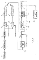
- Figure 1 shows the dual beam transducer 10, coupled to a transceiver 11 and operable, during transmission, to direct a beam of sonar pulses of selected pulse width towards a target. Echo pulses are converted to incoming RF pulses by the transducer.
- the RF pulses are amplified by the preamplifier 12 and channelled via a 20 log R time varied gain receiver 13 (or 40 log R time varied gain receiver 13′) and a 20 log R bandpass filter 14 (or 40 log R bandpass filter 14′), according to the setting of a selector switch 15, to a selectable gain amplifier 16.
- the RF signal from the amplifier 16 is gated in known manner via a blanker 17 to a mixer 18, fed by a local oscillator 19, the resultant IF signal being filtered by a selectable bandwidth filter 20.
- the filtered output is applied to a full wave detector 21, the detected output pulse passing by a low pass filter 22 to data processing and recording equipment 23.
- the present invention provides a signal processing system which overcomes this disadvantage.
- the modified system according to the present invention is illustrated in Figure 2, wherein components which are common to the system of Figure 1 are denoted by the same reference numerals.
- the RF signal downstream of the blanker 17 is received by a wideband sonar detector module 24, which replaces the components 18, 19, 20, 21 and 22 of Figure 1.
- This module 24 consists essentially of a wideband input amplifier 25, a wideband full wave detector 26, and a low pass filter 27.
- the module 24 eliminates an intermediate stage and provides demodulation of the received pulses at a wide enough bandwidth to conserve valuable information which would otherwise be lost by elimination of the higher fourier components of the signal.
- the module 24 is illustrated in greater detail in Figure 3.
- the input amplifier 25 of the module 24 preferably has a bandwidth of at least 1.2 MHz, in which case it will accommodate sonar frequencies of 420 kHz and lower, but in any event must have a bandwidth of at least 500 kHz.
- the amplifier 25 has a typical gain of 20 dB.
- the output of the amplifier is applied to the input of the full wave detector 26, consisting of two integrated circuits 28, 29 connected in circuit as shown so as to incorporate a 50 kHz filter for the detected signal.
- the output of the detector 26 is applied to the filter 27, which is an active low pass filter having a cut off frequency of 50 kHz.
- Single targets included a ping pong ball, a steel ball, a styrofoam ball, air bubbles, a leaf and other shapes. Some shapes were similar in diameter (e.g. ping pong ball with and without water, styrofoam ball #5), while others were not (e.g. air bubble wand, leaf).
- the intent here was to determine whether the equipment could show differences, at least qualitatively, in the reflected signals of various targets.
- Data collected on sturgeon Acipenser fluvescens
- walleye Stizostedion vitreum
- Both single and multiple target experiments involved transmitted pulse widths of 0.5 ms and 0.1 ms which theoretically corresponded to spatial resolutions of targets at 37.5 and 7.5 cm., respectively.
- comparisons were made of the reflected signals between the two methods expressed as both time domain plots and power spectra (fast fourier transformation of FFT's).
- Taped time domain signals for both transmitted pulse widths were plotted off either Racal or DAT recorders using a HP 7460A plotter. The plot for each target was based on only one signal, and was assumed to be representable of signal, during the experimental period.
- mean pulse width at -6 dB level
- Peak amplitude levels were also estimated (at 0 dB level) using the ESP.
- Typical power spectra were constructed from the recorded signals using a Nicolet 660B analyzer.
- the dual beam transducer 10 was used to estimate target strength since it could correct for the target being off-axis.
- ESP dual beam processing
- the echoes were received on both the 6 and 15 degree elements.
- the signals were amplified using a time varied gain amplifier and analyzed.
- Target strengths were estimated for most shapes approximately 3.1 m from the transducer which was expected to be in a "free-field" measurement zone.
- Target strengths of sturgeon, walleye and other species were also estimated for both individuals and groups. Comparisons were made of the estimated target strengths of the ping pong balls using both the existing and modified sounder with a 0.5 ms transmitted pulse.
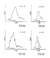
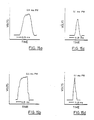
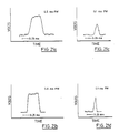
- Figures 5-27 consists of four diagrams showing comparative results obtained using the two equipments, and wherein: Figures 5a-27a show results obtained with the known equipment using transmitted pulses at 0.5 ms pulse width; Figures 5b-27b show results obtained with the new equipment using transmitted pulses at 0.5 ms pulse width; Figures 5c-27c show results obtained with the known equipment using transmitted pulses at 0.1 ms pulse width; and Figures 5d-27d show results obtained with the new equipment using transmitted pulses at 0.1 ms pulse width.
- Figures 5a-5d show the results obtained from experiments involving four sets of three ping pong balls, the sets being spaced approximately 10-15 cm apart at various distances from the transducers.
- the experiments were conducted at transmitted pulse widths of 0.1 ms and 0.5 ms, which theoretically correspond to spatial resolutions of approximately 7.5 cm. and 37.5 cm. respectively.
- Figures 6-10 show comparative results obtained using the two equipments, operating at the two transmitted pulse widths 0.5 ms and 0.1 ms as previously discussed.
- the curves shown in the diagrams are time domain plots of selected single targets, namely, a ping pong ball (Figure 6), a ping pong ball filled with water (Figure 7), a styrofoam ball (Figure 8), a leaf ( Figure 9) and air bubbles ( Figure 10).
- the plots are obtained for both equipments at 0.5 ms pulse width are better defined than those obtained at 0.1 ms pulse width.
- the signals obtained using the equipment of the present invention differ from those obtained using the known equipment.
- the rise times are considerably sharper for all targets than those obtained using the known equipment.
- the signals obtained using the new equipment are better defined - see particularly Figures 7-10.
- Figures 11-27 relates to a specific target, which is identified in Table 2.
- Figure 28 shows power spectrum plots, using the known equipment, for sturgeon 80 cm. long oriented in three different aspects.
- Figure 29 shows the plots obtained with the same targets using the equipment of the present invention. It will be noted that the new equipment can more readily differentiate between the fish orientations.
- Figure 30 shows power spectrum plots, using the new equipment, for various sizes of sturgeon, 42 cm., 50 cm., cm., 70 cm., and 80 cm.
- Figure 31 shows for comparison two power spectrum plots, using both the known equipment and the new equipment, where the target is a steel ball. It is evident that the new equipment preserves more information provided by the received signals.
- Figure 32 shows the comparative power spectrum plots for the two equipments where the target is a bark chip.
- Figure 33 similarly shows the comparative plots where the target is a leaf.
- Figure 34 similarly shows the comparative plots where the target is a ping pong ball.
- Figure 35 similarly shows the comparative plots where the target is a ping pong ball filled with water.
- Figure 36 similarly shows the comparative plots where the target is a styrofoam ball.
- Figure 37 shows the comparative plots where air bubbles are the target.
Landscapes
- Engineering & Computer Science (AREA)
- Computer Networks & Wireless Communication (AREA)
- Physics & Mathematics (AREA)
- General Physics & Mathematics (AREA)
- Radar, Positioning & Navigation (AREA)
- Remote Sensing (AREA)
- Measurement Of Velocity Or Position Using Acoustic Or Ultrasonic Waves (AREA)
- Superconductors And Manufacturing Methods Therefor (AREA)
- Diaphragms For Electromechanical Transducers (AREA)
- Dental Preparations (AREA)
- Steroid Compounds (AREA)
Applications Claiming Priority (2)
| Application Number | Priority Date | Filing Date | Title |
|---|---|---|---|
| US360200 | 1989-06-01 | ||
| US07/360,200 US4949318A (en) | 1989-06-01 | 1989-06-01 | Hydroacoustic sonar equipment |
Publications (3)
| Publication Number | Publication Date |
|---|---|
| EP0400919A2 true EP0400919A2 (fr) | 1990-12-05 |
| EP0400919A3 EP0400919A3 (fr) | 1992-02-12 |
| EP0400919B1 EP0400919B1 (fr) | 1995-08-23 |
Family
ID=23416997
Family Applications (1)
| Application Number | Title | Priority Date | Filing Date |
|---|---|---|---|
| EP90305727A Expired - Lifetime EP0400919B1 (fr) | 1989-06-01 | 1990-05-25 | Equipement à sonar hydroacoustique et méthode |
Country Status (13)
| Country | Link |
|---|---|
| US (1) | US4949318A (fr) |
| EP (1) | EP0400919B1 (fr) |
| JP (1) | JP2505911B2 (fr) |
| AT (1) | ATE126896T1 (fr) |
| AU (1) | AU617281B2 (fr) |
| CA (1) | CA1292305C (fr) |
| DE (1) | DE69021777T2 (fr) |
| DK (1) | DK0400919T3 (fr) |
| ES (1) | ES2076316T3 (fr) |
| FI (1) | FI902509A0 (fr) |
| GR (1) | GR3017938T3 (fr) |
| NO (1) | NO902397L (fr) |
| NZ (1) | NZ233872A (fr) |
Cited By (2)
| Publication number | Priority date | Publication date | Assignee | Title |
|---|---|---|---|---|
| ES2041576A1 (es) * | 1991-04-16 | 1993-11-16 | Ryokuseisha Kk | Aparato para codificar informacion de imagen de localizador de cardumenes (bancos de peces) y metodo de transmision. |
| WO2001031363A1 (fr) * | 1999-10-28 | 2001-05-03 | Guigné International, Ltd. | Systeme de sonar evaluant la dimension des poissons |
Families Citing this family (8)
| Publication number | Priority date | Publication date | Assignee | Title |
|---|---|---|---|---|
| US5260912A (en) * | 1991-05-17 | 1993-11-09 | Computrol, Inc. | Side-looking fish finder |
| US7688675B2 (en) * | 2006-03-24 | 2010-03-30 | University Of Mississippi | Underwater biomass assessment device and method |
| CN101813771B (zh) * | 2009-12-08 | 2013-04-24 | 中国科学院声学研究所 | 一种海豚仿生声纳信号处理方法 |
| WO2013063515A2 (fr) | 2011-10-26 | 2013-05-02 | Flir Systems, Inc. | Sonar à bande large avec compression d'impulsion |
| CN204495996U (zh) | 2011-10-26 | 2015-07-22 | 菲力尔系统公司 | 宽带声纳接收器 |
| US10444354B2 (en) | 2011-10-26 | 2019-10-15 | Flir Systems, Inc. | Sonar data enhancement systems and methods |
| CN106886015B (zh) * | 2017-02-23 | 2018-02-09 | 山东科技大学 | 一种多波束声呐主要声学指标的检测装置及检测方法 |
| CN113433552A (zh) * | 2021-08-25 | 2021-09-24 | 宁波博海深衡科技有限公司武汉分公司 | 多信道信号发射和接收电子系统 |
Citations (3)
| Publication number | Priority date | Publication date | Assignee | Title |
|---|---|---|---|---|
| US3952280A (en) * | 1974-01-10 | 1976-04-20 | Esl Incorporated | Radiation monitoring of an object space with a clutter suppression technique |
| US4081783A (en) * | 1975-09-26 | 1978-03-28 | Keisuke Honda | Fish finder capable of discriminating sizes of fish |
| FR2596163A1 (fr) * | 1986-03-19 | 1987-09-25 | Onera (Off Nat Aerospatiale) | Procede et appareil pour la discrimination a distance de cibles |
Family Cites Families (7)
| Publication number | Priority date | Publication date | Assignee | Title |
|---|---|---|---|---|
| JPS5132667A (ja) * | 1974-09-13 | 1976-03-19 | Masaki Yoshimura | Choonpaidobutsutaikenshutsuki |
| US4016750B1 (en) * | 1975-11-06 | 1994-04-05 | Stanford Research Inst | Ultrasonic imaging method and apparatus |
| US4069468A (en) * | 1976-09-24 | 1978-01-17 | Raytheon Company | Doppler spectral measurement |
| US4119941A (en) * | 1977-08-08 | 1978-10-10 | The United States Of America As Represented By The Secretary Of The Navy | Acoustic coupler |
| JPS58112533A (ja) * | 1981-12-25 | 1983-07-05 | 横河電機株式会社 | 反射波受信方式 |
| JPS5960378A (ja) * | 1982-09-30 | 1984-04-06 | Yokogawa Hokushin Electric Corp | 反射波信号受信方法 |
| JPS60104109U (ja) * | 1983-12-21 | 1985-07-16 | 横河メディカルシステム株式会社 | マルチビ−ム式イメ−ジヤ |
-
1989
- 1989-06-01 US US07/360,200 patent/US4949318A/en not_active Expired - Lifetime
- 1989-06-14 CA CA000602788A patent/CA1292305C/fr not_active Expired - Lifetime
-
1990
- 1990-05-21 FI FI902509A patent/FI902509A0/fi not_active IP Right Cessation
- 1990-05-24 AU AU55866/90A patent/AU617281B2/en not_active Ceased
- 1990-05-25 DK DK90305727.1T patent/DK0400919T3/da active
- 1990-05-25 ES ES90305727T patent/ES2076316T3/es not_active Expired - Lifetime
- 1990-05-25 AT AT90305727T patent/ATE126896T1/de active
- 1990-05-25 EP EP90305727A patent/EP0400919B1/fr not_active Expired - Lifetime
- 1990-05-25 DE DE69021777T patent/DE69021777T2/de not_active Expired - Fee Related
- 1990-05-30 NO NO90902397A patent/NO902397L/no unknown
- 1990-05-30 NZ NZ233872A patent/NZ233872A/en unknown
- 1990-06-01 JP JP2144237A patent/JP2505911B2/ja not_active Expired - Lifetime
-
1995
- 1995-11-01 GR GR950403046T patent/GR3017938T3/el unknown
Patent Citations (3)
| Publication number | Priority date | Publication date | Assignee | Title |
|---|---|---|---|---|
| US3952280A (en) * | 1974-01-10 | 1976-04-20 | Esl Incorporated | Radiation monitoring of an object space with a clutter suppression technique |
| US4081783A (en) * | 1975-09-26 | 1978-03-28 | Keisuke Honda | Fish finder capable of discriminating sizes of fish |
| FR2596163A1 (fr) * | 1986-03-19 | 1987-09-25 | Onera (Off Nat Aerospatiale) | Procede et appareil pour la discrimination a distance de cibles |
Cited By (2)
| Publication number | Priority date | Publication date | Assignee | Title |
|---|---|---|---|---|
| ES2041576A1 (es) * | 1991-04-16 | 1993-11-16 | Ryokuseisha Kk | Aparato para codificar informacion de imagen de localizador de cardumenes (bancos de peces) y metodo de transmision. |
| WO2001031363A1 (fr) * | 1999-10-28 | 2001-05-03 | Guigné International, Ltd. | Systeme de sonar evaluant la dimension des poissons |
Also Published As
| Publication number | Publication date |
|---|---|
| CA1292305C (fr) | 1991-11-19 |
| NO902397D0 (no) | 1990-05-30 |
| EP0400919B1 (fr) | 1995-08-23 |
| FI902509A0 (fi) | 1990-05-21 |
| ATE126896T1 (de) | 1995-09-15 |
| AU617281B2 (en) | 1991-11-21 |
| NO902397L (no) | 1990-12-03 |
| EP0400919A3 (fr) | 1992-02-12 |
| AU5586690A (en) | 1990-12-06 |
| DK0400919T3 (da) | 1995-09-25 |
| ES2076316T3 (es) | 1995-11-01 |
| DE69021777T2 (de) | 1996-02-22 |
| NZ233872A (en) | 1992-07-28 |
| JP2505911B2 (ja) | 1996-06-12 |
| JPH0387682A (ja) | 1991-04-12 |
| DE69021777D1 (de) | 1995-09-28 |
| GR3017938T3 (en) | 1996-02-29 |
| US4949318A (en) | 1990-08-14 |
Similar Documents
| Publication | Publication Date | Title |
|---|---|---|
| JP3573783B2 (ja) | ソナー・システム | |
| EP0400919B1 (fr) | Equipement à sonar hydroacoustique et méthode | |
| Traynor et al. | Evaluation of the dual beam acoustic fish target strength measurement method | |
| US6366232B1 (en) | Method and sensor for detecting foreign bodies in a medium with a radar | |
| US8638641B2 (en) | Real-time robust method for determining the trajectory of one or more cetaceans by means of passive acoustics, using a laptop computer | |
| JPH06222131A (ja) | レーダ検波閾値調整方法及びその装置 | |
| EP0156636B1 (fr) | Traitement de signaux écho | |
| CN109188430A (zh) | 一种基于地面监视雷达系统的目标提取方法 | |
| CN111046025B (zh) | 无人机信号探测方法及装置 | |
| AU646976B2 (en) | Ultrasonic ranging devices | |
| CN116953087A (zh) | 一种桥梁节段拼装施工质量智能检测方法 | |
| WO2001018562A1 (fr) | Procede de detection de poissons a l'aide de donnees sonar | |
| JP2770814B2 (ja) | アクティブソーナー装置 | |
| Patrick et al. | Range detection of targets using hydroacoustics in the laboratory | |
| JP2576622B2 (ja) | 妨害信号検出装置 | |
| Guillard et al. | Application of mobile acoustic techniques fish surveys in shallow water: the river Seine | |
| JP6113949B2 (ja) | アクティブソーナー装置、アクティブソーナー装置における信号正規化方法およびそのプログラム | |
| Holtz et al. | Digitizer Performance under Conditions of Linear and Circular Antenna Polarization. | |
| Bozzano et al. | Underwater vegetation detection in high frequency sonar images: A preliminary approach | |
| Bozzano et al. | A high frequency approach for seabed vegetation characterization | |
| JPH0875709A (ja) | 超音波探傷による欠陥種判別方法及び装置 | |
| CN117970296A (zh) | 二次回波导致声呐假底的剔除方法、装置、设备和介质 | |
| Vent | Fish school target strength and Doppler measurements | |
| CN118091593A (zh) | 基于参考单元筛选的posglt-cfar检测算法 | |
| CN117687008A (zh) | 一种主动声纳发射脉冲盲检测方法 |
Legal Events
| Date | Code | Title | Description |
|---|---|---|---|
| PUAI | Public reference made under article 153(3) epc to a published international application that has entered the european phase |
Free format text: ORIGINAL CODE: 0009012 |
|
| AK | Designated contracting states |
Kind code of ref document: A2 Designated state(s): AT BE CH DE DK ES FR GB GR IT LI LU NL SE |
|
| PUAL | Search report despatched |
Free format text: ORIGINAL CODE: 0009013 |
|
| AK | Designated contracting states |
Kind code of ref document: A3 Designated state(s): AT BE CH DE DK ES FR GB GR IT LI LU NL SE |
|
| 17P | Request for examination filed |
Effective date: 19920731 |
|
| RIN1 | Information on inventor provided before grant (corrected) |
Inventor name: SIM, BLAIR F. Inventor name: HUNT, GERALD A. Inventor name: PATRICK, PAUL H. |
|
| RAP1 | Party data changed (applicant data changed or rights of an application transferred) |
Owner name: ONTARIO HYDRO |
|
| 17Q | First examination report despatched |
Effective date: 19940207 |
|
| GRAA | (expected) grant |
Free format text: ORIGINAL CODE: 0009210 |
|
| AK | Designated contracting states |
Kind code of ref document: B1 Designated state(s): AT BE CH DE DK ES FR GB GR IT LI LU NL SE |
|
| PG25 | Lapsed in a contracting state [announced via postgrant information from national office to epo] |
Ref country code: GR Free format text: LAPSE BECAUSE OF FAILURE TO SUBMIT A TRANSLATION OF THE DESCRIPTION OR TO PAY THE FEE WITHIN THE PRESCRIBED TIME-LIMIT Effective date: 19950823 |
|
| REF | Corresponds to: |
Ref document number: 126896 Country of ref document: AT Date of ref document: 19950915 Kind code of ref document: T |
|
| REG | Reference to a national code |
Ref country code: DK Ref legal event code: T3 |
|
| REF | Corresponds to: |
Ref document number: 69021777 Country of ref document: DE Date of ref document: 19950928 |
|
| ET | Fr: translation filed | ||
| REG | Reference to a national code |
Ref country code: ES Ref legal event code: FG2A Ref document number: 2076316 Country of ref document: ES Kind code of ref document: T3 |
|
| ITF | It: translation for a ep patent filed |
Owner name: MARIETTI E GISLON S.R.L. |
|
| REG | Reference to a national code |
Ref country code: GR Ref legal event code: FG4A Free format text: 3017938 |
|
| PG25 | Lapsed in a contracting state [announced via postgrant information from national office to epo] |
Ref country code: DK Effective date: 19960525 Ref country code: AT Effective date: 19960525 |
|
| REG | Reference to a national code |
Ref country code: DK Ref legal event code: EBP |
|
| PG25 | Lapsed in a contracting state [announced via postgrant information from national office to epo] |
Ref country code: SE Effective date: 19960526 |
|
| PG25 | Lapsed in a contracting state [announced via postgrant information from national office to epo] |
Ref country code: ES Free format text: LAPSE BECAUSE OF NON-PAYMENT OF DUE FEES Effective date: 19960527 |
|
| PG25 | Lapsed in a contracting state [announced via postgrant information from national office to epo] |
Ref country code: LU Free format text: LAPSE BECAUSE OF NON-PAYMENT OF DUE FEES Effective date: 19960531 Ref country code: LI Effective date: 19960531 Ref country code: CH Effective date: 19960531 Ref country code: BE Effective date: 19960531 |
|
| PLBE | No opposition filed within time limit |
Free format text: ORIGINAL CODE: 0009261 |
|
| STAA | Information on the status of an ep patent application or granted ep patent |
Free format text: STATUS: NO OPPOSITION FILED WITHIN TIME LIMIT |
|
| 26N | No opposition filed | ||
| BERE | Be: lapsed |
Owner name: ONTARIO HYDRO Effective date: 19960531 |
|
| PG25 | Lapsed in a contracting state [announced via postgrant information from national office to epo] |
Ref country code: NL Effective date: 19961201 |
|
| REG | Reference to a national code |
Ref country code: GR Ref legal event code: MM2A Free format text: 3017938 |
|
| REG | Reference to a national code |
Ref country code: CH Ref legal event code: PL |
|
| EUG | Se: european patent has lapsed |
Ref document number: 90305727.1 |
|
| NLV4 | Nl: lapsed or anulled due to non-payment of the annual fee |
Effective date: 19961201 |
|
| PGFP | Annual fee paid to national office [announced via postgrant information from national office to epo] |
Ref country code: FR Payment date: 19970522 Year of fee payment: 8 |
|
| PGFP | Annual fee paid to national office [announced via postgrant information from national office to epo] |
Ref country code: GB Payment date: 19970523 Year of fee payment: 8 |
|
| PGFP | Annual fee paid to national office [announced via postgrant information from national office to epo] |
Ref country code: DE Payment date: 19970623 Year of fee payment: 8 |
|
| PG25 | Lapsed in a contracting state [announced via postgrant information from national office to epo] |
Ref country code: GB Free format text: LAPSE BECAUSE OF NON-PAYMENT OF DUE FEES Effective date: 19980525 |
|
| PG25 | Lapsed in a contracting state [announced via postgrant information from national office to epo] |
Ref country code: FR Free format text: LAPSE BECAUSE OF NON-PAYMENT OF DUE FEES Effective date: 19980531 |
|
| GBPC | Gb: european patent ceased through non-payment of renewal fee |
Effective date: 19980525 |
|
| PG25 | Lapsed in a contracting state [announced via postgrant information from national office to epo] |
Ref country code: DE Free format text: LAPSE BECAUSE OF NON-PAYMENT OF DUE FEES Effective date: 19990302 |
|
| REG | Reference to a national code |
Ref country code: FR Ref legal event code: ST |
|
| REG | Reference to a national code |
Ref country code: ES Ref legal event code: FD2A Effective date: 19990301 |
|
| PG25 | Lapsed in a contracting state [announced via postgrant information from national office to epo] |
Ref country code: IT Free format text: LAPSE BECAUSE OF NON-PAYMENT OF DUE FEES;WARNING: LAPSES OF ITALIAN PATENTS WITH EFFECTIVE DATE BEFORE 2007 MAY HAVE OCCURRED AT ANY TIME BEFORE 2007. THE CORRECT EFFECTIVE DATE MAY BE DIFFERENT FROM THE ONE RECORDED. Effective date: 20050525 |