EP0400777B1 - Method of inspecting die for forming honeycomb structure - Google Patents
Method of inspecting die for forming honeycomb structure Download PDFInfo
- Publication number
- EP0400777B1 EP0400777B1 EP90302070A EP90302070A EP0400777B1 EP 0400777 B1 EP0400777 B1 EP 0400777B1 EP 90302070 A EP90302070 A EP 90302070A EP 90302070 A EP90302070 A EP 90302070A EP 0400777 B1 EP0400777 B1 EP 0400777B1
- Authority
- EP
- European Patent Office
- Prior art keywords
- die
- rear apertures
- face
- photosensitive means
- slits
- Prior art date
- Legal status (The legal status is an assumption and is not a legal conclusion. Google has not performed a legal analysis and makes no representation as to the accuracy of the status listed.)
- Expired - Lifetime
Links
- 238000000034 method Methods 0.000 title claims description 14
- 238000009826 distribution Methods 0.000 claims description 4
- 230000001788 irregular Effects 0.000 claims description 4
- 230000001678 irradiating effect Effects 0.000 claims description 2
- 239000000919 ceramic Substances 0.000 description 11
- 235000019592 roughness Nutrition 0.000 description 7
- 238000007689 inspection Methods 0.000 description 5
- 238000009792 diffusion process Methods 0.000 description 3
- 239000011521 glass Substances 0.000 description 3
- 230000003746 surface roughness Effects 0.000 description 3
- 239000000969 carrier Substances 0.000 description 1
- 239000003054 catalyst Substances 0.000 description 1
- 238000001816 cooling Methods 0.000 description 1
- 230000007547 defect Effects 0.000 description 1
- 230000003111 delayed effect Effects 0.000 description 1
- 238000001125 extrusion Methods 0.000 description 1
- 239000007789 gas Substances 0.000 description 1
- 239000005337 ground glass Substances 0.000 description 1
- 238000004519 manufacturing process Methods 0.000 description 1
Images


Classifications
-
- G—PHYSICS
- G01—MEASURING; TESTING
- G01N—INVESTIGATING OR ANALYSING MATERIALS BY DETERMINING THEIR CHEMICAL OR PHYSICAL PROPERTIES
- G01N21/00—Investigating or analysing materials by the use of optical means, i.e. using sub-millimetre waves, infrared, visible or ultraviolet light
- G01N21/84—Systems specially adapted for particular applications
- G01N21/88—Investigating the presence of flaws or contamination
- G01N21/95—Investigating the presence of flaws or contamination characterised by the material or shape of the object to be examined
- G01N21/956—Inspecting patterns on the surface of objects
- G01N21/95692—Patterns showing hole parts, e.g. honeycomb filtering structures
-
- G—PHYSICS
- G01—MEASURING; TESTING
- G01B—MEASURING LENGTH, THICKNESS OR SIMILAR LINEAR DIMENSIONS; MEASURING ANGLES; MEASURING AREAS; MEASURING IRREGULARITIES OF SURFACES OR CONTOURS
- G01B11/00—Measuring arrangements characterised by the use of optical techniques
- G01B11/30—Measuring arrangements characterised by the use of optical techniques for measuring roughness or irregularity of surfaces
-
- G—PHYSICS
- G01—MEASURING; TESTING
- G01N—INVESTIGATING OR ANALYSING MATERIALS BY DETERMINING THEIR CHEMICAL OR PHYSICAL PROPERTIES
- G01N21/00—Investigating or analysing materials by the use of optical means, i.e. using sub-millimetre waves, infrared, visible or ultraviolet light
- G01N21/17—Systems in which incident light is modified in accordance with the properties of the material investigated
- G01N2021/1765—Method using an image detector and processing of image signal
- G01N2021/1768—Method using an image detector and processing of image signal using photographic film
Definitions
- This invention relates to a method of inspecting a die for forming honeycomb structures, and more particularly to a method of inspecting a die for forming honeycomb structures, which is able to precisely inspect worked conditions of inner surfaces in a great many rear apertures for supplying ceramic batches into the die.
- Ceramic honeycomb structures have been widely used as catalyst carriers for purifying exhaust gases of automobiles. Such ceramic honeycomb structures are generally formed by extruding ceramic batches through a honeycomb forming die having slits of narrow widths of the order of 0.1-0.2 mm and a great number (as much as thousands) of rear apertures communicating with the slits for supplying the ceramic batches.
- the method of inspecting a die having slits of narrow widths and a number of rear apertures communicating with the slits for forming honeycomb structures by extruding batches through said die comprises steps of irradiating light onto an end face of the die on a side of the slits, detecting intensities of light beams arriving at an end face of the die on a side of the rear apertures by irregular reflection at inner surfaces of the rear apertures by means of photosensitive means and determining roughness distributions of the inner surfaces of the number of rear apertures from relative intensities at the photosensitive means.
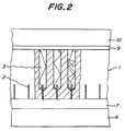
- Figs. 1 and 2 illustrate a die 1 for forming honeycomb structures, which is to be inspected.
- the die 1 includes a number of slits 2 having very narrow widths and a number (as much as thousands) of rear apertures 3 communicating with the slits 2, respectively, for supplying ceramic batches.
- Such a die 1 is arranged through a support glass plate 6 and a light diffusion plate 7 such as a ground glass on an open upper surface of an inspection table 5 having light sources 4 therein.
- a light diffusion plate 7 such as a ground glass on an open upper surface of an inspection table 5 having light sources 4 therein.
- an end face of the die 1 on a side of the slits 2 is arranged facing to the light diffusion plate 7.
- the light sources 4 and the support glass plate 6 are arranged so that light beams from the light sources 4 have substantially equal intensities at a surface of the support glass plate 6 as shown in Fig. 2. It is further preferable to provide a fan 8 for cooling the inside of the inspection table 5.
- photosensitive means 9 is provided on the other end face of the die 1 on a side of the rear apertures 3.
- the photosensitive means 9 is, for example, a sensitized paper which is brought into close contact with the end face of the die 1 by means of a weight 10.
- light sources 4 radiating light beams of wave lengths to which the sensitized paper is most susceptible.
- means such as an image reader may be used as the photosensitive means 9, which is able to directly convert intensities of light into electric signals which are arithmetically processed to output inspection results onto a TV monitor.
- the diffused light beams are irradiated uniformly into the number (as much as thousands) of the rear apertures 3 and irregularly reflected at inner surfaces of the rear apertures 3 to arrive at the end face of the die 1 on the side of the rear apertures 3.
- the degree of the irregular reflection becomes large.
- the degree of the irregular reflection becomes small. Therefore, the intensity of the diffused light beams arrived at the end face of the die 1 on the side of the rear apertures 3 through rear apertures having rougher inner surfaces is lower than that of the diffused light beams through rear apertures having smoother inner surfaces.
- Such an intensity of the diffused light beams can be detected by the degree of bright and dark of light beams with the aid of the photosensitive means 9 such as a sensitized paper located on the end face of the die 1 on the side of the rear apertures 3. It is necessary to bring the photosensitive means 9 into close contact with the end face of the die 1 on the side of the rear apertures 3 in order to improve the inspection accuracy. If there is any clearance between the photosensitive means 9 and the end face of the die 1, clear bright and dark images may not be obtained.
- the photosensitive means 9 such as a sensitized paper located on the end face of the die 1 on the side of the rear apertures 3. It is necessary to bring the photosensitive means 9 into close contact with the end face of the die 1 on the side of the rear apertures 3 in order to improve the inspection accuracy. If there is any clearance between the photosensitive means 9 and the end face of the die 1, clear bright and dark images may not be obtained.
- Fig. 3 illustrates examples of the images obtained on the photosensitive means 9. It is clear from the illustration that rear apertures 3 of the die 1 corresponding to partially dark portions 11 were worked badly or with rougher inner surfaces. The die 1 whose images were shown in Fig. 3 was actually set in an extruder to form honeycomb structures. As a result, it was ascertained that flowing resistance of ceramic batches through the apertures corresponding to the dark portions 11 was larger than those through remaining apertures. Therefore, the extrusion of the ceramic batch through the apertures corresponding to the dark portions was delayed so that structures (formed bodies) having uniform sections could not be obtained.
- diffused light beams having substantially equal intensities are irradiated from an end face of a die for forming honeycomb structures on a side of slits thereof and intensities of the light beams arrived at the other end face of the die on a side of rear apertures are detected in a simple manner by means of photosensitive means arranged on the other end face of the die. Accordingly, roughness distributions of inner surfaces of great number (as much as thousands) of the rear apertures of the die can be inspected easily and precisely only by one operation according to the invention. Therefore, according to the invention the quality of a die for forming honeycomb structures can be determined rapidly without forming trial honeycomb structures.
- the method of inspecting dies for forming honeycomb structures according to the invention can thus eliminate all the disadvantages of the prior art.
Landscapes
- Physics & Mathematics (AREA)
- General Physics & Mathematics (AREA)
- Biochemistry (AREA)
- Life Sciences & Earth Sciences (AREA)
- Chemical & Material Sciences (AREA)
- Analytical Chemistry (AREA)
- Health & Medical Sciences (AREA)
- General Health & Medical Sciences (AREA)
- Immunology (AREA)
- Pathology (AREA)
- Investigating Materials By The Use Of Optical Means Adapted For Particular Applications (AREA)
- Length Measuring Devices By Optical Means (AREA)
- Press-Shaping Or Shaping Using Conveyers (AREA)
Description
- This invention relates to a method of inspecting a die for forming honeycomb structures, and more particularly to a method of inspecting a die for forming honeycomb structures, which is able to precisely inspect worked conditions of inner surfaces in a great many rear apertures for supplying ceramic batches into the die.
- Ceramic honeycomb structures have been widely used as catalyst carriers for purifying exhaust gases of automobiles. Such ceramic honeycomb structures are generally formed by extruding ceramic batches through a honeycomb forming die having slits of narrow widths of the order of 0.1-0.2 mm and a great number (as much as thousands) of rear apertures communicating with the slits for supplying the ceramic batches.
- It is obvious that the quality of formed honeycomb structures is directly affected by configurations and dimensional accuracy of the slits of such honeycomb forming dies. In addition, since flow resistance of ceramic batches passing through rear apertures of the die is affected by roughness of inner surfaces of the rear apertures for supplying the ceramic batches, it is needed to work the rear apertures so as to obtain uniform inner surface roughness in order to prevent malformed honeycomb structures. However, these rear apertures are numerous and very deep relative to their diameters so that surface roughness tester could not be used for measuring surface roughness on inner surfaces of the rear apertures. There has been no suitable inspecting method for this purpose. Therefore, when a new honeycomb forming die is used, it is unavoidable that the die is set in an extruding machine and honeycomb structures are actually formed whose defects are used for determining whether roughness of the rear apertures of the die fulfil the requirement or not. Such a judgment requires troublesome and time-consuming operations and gives rise to confusion in a production shop.
- It is an object of the invention to provide a method of inspecting dies for forming honeycomb structures, which eliminates all the disadvantages of the prior art and is capable of simply and precisely inspecting roughness distributions, greatly affecting quality of honeycomb structures, of inner surfaces of rear apertures for supplying ceramic batches.
- With this in mind, the method of inspecting a die having slits of narrow widths and a number of rear apertures communicating with the slits for forming honeycomb structures by extruding batches through said die according to the invention, comprises steps of irradiating light onto an end face of the die on a side of the slits, detecting intensities of light beams arriving at an end face of the die on a side of the rear apertures by irregular reflection at inner surfaces of the rear apertures by means of photosensitive means
and determining roughness distributions of the inner surfaces of the number of rear apertures from relative intensities at the photosensitive means. - The invention will be more fully understood by referring to the following detailed description of an embodiment, illustrated in the appended drawings.
- Fig. 1 is a sectional view for explaining one inspection method embodying the invention;
- Fig. 2 is an enlarged sectional view of main parts shown in Fig. 1; and
- Fig. 3 is a plan view illustrating images obtained on photosensitive means used in the embodiment.
- Figs. 1 and 2 illustrate a die 1 for forming honeycomb structures, which is to be inspected. The die 1 includes a number of
slits 2 having very narrow widths and a number (as much as thousands) of rear apertures 3 communicating with theslits 2, respectively, for supplying ceramic batches. Such a die 1 is arranged through asupport glass plate 6 and alight diffusion plate 7 such as a ground glass on an open upper surface of an inspection table 5 having light sources 4 therein. In this case, an end face of the die 1 on a side of theslits 2 is arranged facing to thelight diffusion plate 7. It is further preferable to arrange the light sources 4 and thesupport glass plate 6 so that light beams from the light sources 4 have substantially equal intensities at a surface of thesupport glass plate 6 as shown in Fig. 2. It is further preferable to provide afan 8 for cooling the inside of the inspection table 5. - On the other hand,
photosensitive means 9 is provided on the other end face of the die 1 on a side of the rear apertures 3. Thephotosensitive means 9 is, for example, a sensitized paper which is brought into close contact with the end face of the die 1 by means of aweight 10. In this case, it is preferable to use light sources 4 radiating light beams of wave lengths to which the sensitized paper is most susceptible. As an alternative, means such as an image reader may be used as thephotosensitive means 9, which is able to directly convert intensities of light into electric signals which are arithmetically processed to output inspection results onto a TV monitor. - With this arrangement, when light beams of the uniform intensity diffused through the
light diffusion plate 6 are directed onto the end face of the die 1 on the side of theslits 2, the diffused light beams are irradiated uniformly into the number (as much as thousands) of the rear apertures 3 and irregularly reflected at inner surfaces of the rear apertures 3 to arrive at the end face of the die 1 on the side of the rear apertures 3. In this case, if roughnesses of the inner surfaces of the rear apertures 3 are fairly large, the degree of the irregular reflection becomes large. On the other hand, if the roughnesses of the inner surfaces of the rear apertures 3 are small, the degree of the irregular reflection becomes small. Therefore, the intensity of the diffused light beams arrived at the end face of the die 1 on the side of the rear apertures 3 through rear apertures having rougher inner surfaces is lower than that of the diffused light beams through rear apertures having smoother inner surfaces. - Such an intensity of the diffused light beams can be detected by the degree of bright and dark of light beams with the aid of the photosensitive means 9 such as a sensitized paper located on the end face of the die 1 on the side of the rear apertures 3. It is necessary to bring the
photosensitive means 9 into close contact with the end face of the die 1 on the side of the rear apertures 3 in order to improve the inspection accuracy. If there is any clearance between the photosensitive means 9 and the end face of the die 1, clear bright and dark images may not be obtained. - Fig. 3 illustrates examples of the images obtained on the photosensitive means 9. It is clear from the illustration that rear apertures 3 of the die 1 corresponding to partially dark portions 11 were worked badly or with rougher inner surfaces. The die 1 whose images were shown in Fig. 3 was actually set in an extruder to form honeycomb structures. As a result, it was ascertained that flowing resistance of ceramic batches through the apertures corresponding to the dark portions 11 was larger than those through remaining apertures. Therefore, the extrusion of the ceramic batch through the apertures corresponding to the dark portions was delayed so that structures (formed bodies) having uniform sections could not be obtained.
- As can be seen from the above description, according to the invention diffused light beams having substantially equal intensities are irradiated from an end face of a die for forming honeycomb structures on a side of slits thereof and intensities of the light beams arrived at the other end face of the die on a side of rear apertures are detected in a simple manner by means of photosensitive means arranged on the other end face of the die. Accordingly, roughness distributions of inner surfaces of great number (as much as thousands) of the rear apertures of the die can be inspected easily and precisely only by one operation according to the invention. Therefore, according to the invention the quality of a die for forming honeycomb structures can be determined rapidly without forming trial honeycomb structures.
- The method of inspecting dies for forming honeycomb structures according to the invention can thus eliminate all the disadvantages of the prior art.
Claims (5)
- A method of inspecting a die (1) having slits (2) of narrow widths and a number of rear apertures (3) communicating with the slits for forming honeycomb structures by extruding batches through said die, said method comprising steps of irradiating diffused light beams onto an end face of the die on a side of the slits, detecting intensities of light beams arrived at an end face of the die on a side of the rear apertures by irregular reflection at inner surfaces of the rear apertures by means of photosensitive means (9) arranged at the end face of the die on the side of the rear apertures, and determining roughness distributions of the inner surfaces of the number of rear apertures from relatively bright and dark portions on the photosensitive means.
- A method as set forth in claim 1, wherein a sensitized paper is used as said photosensitive means.
- A method as set forth in claim 1, wherein an image reader is used as said photosensitive means.
- A method as set forth in claim 1, wherein said diffused light beams have a wave length to which said photosensitive means is susceptible.
- A method as set forth in claim 1, wherein said photosensitive means is in close contact with the end face of the die on the side of the rear apertures.
Applications Claiming Priority (2)
| Application Number | Priority Date | Filing Date | Title |
|---|---|---|---|
| JP1049598A JPH0612253B2 (en) | 1989-03-01 | 1989-03-01 | Inspection method of die for forming honeycomb |
| JP49598/89 | 1989-03-01 |
Publications (3)
| Publication Number | Publication Date |
|---|---|
| EP0400777A2 EP0400777A2 (en) | 1990-12-05 |
| EP0400777A3 EP0400777A3 (en) | 1991-09-25 |
| EP0400777B1 true EP0400777B1 (en) | 1994-06-29 |
Family
ID=12835667
Family Applications (1)
| Application Number | Title | Priority Date | Filing Date |
|---|---|---|---|
| EP90302070A Expired - Lifetime EP0400777B1 (en) | 1989-03-01 | 1990-02-27 | Method of inspecting die for forming honeycomb structure |
Country Status (4)
| Country | Link |
|---|---|
| US (1) | US4988887A (en) |
| EP (1) | EP0400777B1 (en) |
| JP (1) | JPH0612253B2 (en) |
| DE (1) | DE69010280T2 (en) |
Families Citing this family (7)
| Publication number | Priority date | Publication date | Assignee | Title |
|---|---|---|---|---|
| JPH07113523B2 (en) * | 1990-06-19 | 1995-12-06 | 日本碍子株式会社 | Honeycomb surface roughness measuring method and surface roughness measuring probe used therefor |
| US5463462A (en) * | 1993-03-31 | 1995-10-31 | Ngk Insulators, Ltd. | Method of and apparatus for inspecting honeycomb-shaped object having plural through holes |
| DE19648272A1 (en) | 1996-11-21 | 1998-05-28 | Emitec Emissionstechnologie | Method and device for determining a cell density of a honeycomb body, in particular for an exhaust gas catalytic converter |
| US7701570B2 (en) * | 2005-12-12 | 2010-04-20 | Corning Incorporated | Collimated light method and system for detecting defects in honeycombs |
| JP2008139184A (en) * | 2006-12-04 | 2008-06-19 | Denso Corp | Inspection method for object having minute gap groove and correction method for the object |
| JP7206234B2 (en) * | 2020-03-30 | 2023-01-17 | 日本碍子株式会社 | Inspection method and inspection apparatus for columnar honeycomb structure made of ceramics |
| CN116642829A (en) * | 2023-07-26 | 2023-08-25 | 合肥金星智控科技股份有限公司 | Steel pipe end face detection device and method |
Family Cites Families (6)
| Publication number | Priority date | Publication date | Assignee | Title |
|---|---|---|---|---|
| US3264481A (en) * | 1963-07-12 | 1966-08-02 | Fmc Corp | Method and apparatus for inspecting spinnerets |
| US4145714A (en) * | 1978-02-27 | 1979-03-20 | Robert W. MacDonald | Television flaw detector for inspecting the wall surface of a hole through a circuit board |
| US4560273A (en) * | 1982-11-30 | 1985-12-24 | Fujitsu Limited | Method and apparatus for inspecting plated through holes in printed circuit boards |
| US4707132A (en) * | 1985-08-05 | 1987-11-17 | Dutton G Wayne | Process for sensing defects on a smooth cylindrical interior surface in tubing |
| JP2522666B2 (en) * | 1987-03-10 | 1996-08-07 | 日本セメント株式会社 | Method for producing alumina-silica based sintered body |
| US4806774A (en) * | 1987-06-08 | 1989-02-21 | Insystems, Inc. | Inspection system for array of microcircuit dies having redundant circuit patterns |
-
1989
- 1989-03-01 JP JP1049598A patent/JPH0612253B2/en not_active Expired - Lifetime
-
1990
- 1990-02-27 DE DE69010280T patent/DE69010280T2/en not_active Expired - Lifetime
- 1990-02-27 EP EP90302070A patent/EP0400777B1/en not_active Expired - Lifetime
- 1990-03-01 US US07/486,921 patent/US4988887A/en not_active Expired - Lifetime
Also Published As
| Publication number | Publication date |
|---|---|
| JPH0612253B2 (en) | 1994-02-16 |
| EP0400777A2 (en) | 1990-12-05 |
| JPH02228513A (en) | 1990-09-11 |
| US4988887A (en) | 1991-01-29 |
| DE69010280D1 (en) | 1994-08-04 |
| DE69010280T2 (en) | 1995-01-19 |
| EP0400777A3 (en) | 1991-09-25 |
Similar Documents
| Publication | Publication Date | Title |
|---|---|---|
| EP3832295B1 (en) | Device and method for checking for surface defect, using image sensor | |
| KR20090096685A (en) | Plate glass defect detection device, plate glass manufacturing method, plate glass article, quality determination of plate glass and plate glass inspection method | |
| US4988887A (en) | Method of inspecting die for forming honeycomb structure | |
| JPS62127652A (en) | Surface defect inspecting device for semiconductor wafer | |
| CA1126854A (en) | Inspection apparatus for defects on patterns | |
| EP2261644B1 (en) | Method for judging whether a semiconductor wafer is a non-defective wafer by using a laser scattering method | |
| GB2032616A (en) | Method and apparatus for detercting surfaces defects in a workpiece | |
| US5943127A (en) | Coined line analyzer | |
| CN118149725B (en) | Device pin detection system | |
| US6046803A (en) | Two and a half dimension inspection system | |
| KR100249599B1 (en) | Apparatus for inspecting optical uniformity and method therefor | |
| JPS6342222B2 (en) | ||
| JP2000094429A (en) | Green sheet manufacturing method and apparatus | |
| KR102744196B1 (en) | Inspection and measurement methods for glossy surfaces | |
| JP3223609B2 (en) | Inspection method of shadow mask | |
| JPH02254308A (en) | Appearance inspection method | |
| JPH06123711A (en) | Hammer missing detection method and device | |
| US5675409A (en) | Plate holder for a surface inspection system | |
| JPH08136473A (en) | Adjusting method and adjusting apparatus for defect detecting apparatus and reference plate therefor | |
| KR19980048011A (en) | Mask inspection device | |
| JP2000146557A (en) | Measuring method for precision of inner surface of through hole and manufacture of base using it | |
| JPS6063449A (en) | Defect inspection equipment | |
| CN121275755A (en) | Sheet panel window detection mechanism and method | |
| JP2004130167A (en) | Product sorting apparatus and product sorting method | |
| JPH11338082A (en) | Adjusting jig for image recognition device |
Legal Events
| Date | Code | Title | Description |
|---|---|---|---|
| PUAI | Public reference made under article 153(3) epc to a published international application that has entered the european phase |
Free format text: ORIGINAL CODE: 0009012 |
|
| AK | Designated contracting states |
Kind code of ref document: A2 Designated state(s): BE DE FR GB IT SE |
|
| PUAL | Search report despatched |
Free format text: ORIGINAL CODE: 0009013 |
|
| AK | Designated contracting states |
Kind code of ref document: A3 Designated state(s): BE DE FR GB IT SE |
|
| 17P | Request for examination filed |
Effective date: 19920226 |
|
| 17Q | First examination report despatched |
Effective date: 19930817 |
|
| GRAA | (expected) grant |
Free format text: ORIGINAL CODE: 0009210 |
|
| AK | Designated contracting states |
Kind code of ref document: B1 Designated state(s): BE DE FR GB IT SE |
|
| REF | Corresponds to: |
Ref document number: 69010280 Country of ref document: DE Date of ref document: 19940804 |
|
| ITF | It: translation for a ep patent filed | ||
| ET | Fr: translation filed | ||
| EAL | Se: european patent in force in sweden |
Ref document number: 90302070.9 |
|
| PGFP | Annual fee paid to national office [announced via postgrant information from national office to epo] |
Ref country code: FR Payment date: 19950214 Year of fee payment: 6 |
|
| PGFP | Annual fee paid to national office [announced via postgrant information from national office to epo] |
Ref country code: GB Payment date: 19950217 Year of fee payment: 6 Ref country code: SE Payment date: 19950217 Year of fee payment: 6 |
|
| PLBE | No opposition filed within time limit |
Free format text: ORIGINAL CODE: 0009261 |
|
| STAA | Information on the status of an ep patent application or granted ep patent |
Free format text: STATUS: NO OPPOSITION FILED WITHIN TIME LIMIT |
|
| 26N | No opposition filed | ||
| PG25 | Lapsed in a contracting state [announced via postgrant information from national office to epo] |
Ref country code: GB Effective date: 19960227 |
|
| PG25 | Lapsed in a contracting state [announced via postgrant information from national office to epo] |
Ref country code: SE Effective date: 19960228 |
|
| GBPC | Gb: european patent ceased through non-payment of renewal fee |
Effective date: 19960227 |
|
| PG25 | Lapsed in a contracting state [announced via postgrant information from national office to epo] |
Ref country code: FR Effective date: 19961031 |
|
| REG | Reference to a national code |
Ref country code: FR Ref legal event code: ST |
|
| PG25 | Lapsed in a contracting state [announced via postgrant information from national office to epo] |
Ref country code: IT Free format text: LAPSE BECAUSE OF NON-PAYMENT OF DUE FEES Effective date: 20050227 |
|
| PGFP | Annual fee paid to national office [announced via postgrant information from national office to epo] |
Ref country code: BE Payment date: 20051230 Year of fee payment: 17 |
|
| BERE | Be: lapsed |
Owner name: *NGK INSULATORS LTD Effective date: 20070228 |
|
| PG25 | Lapsed in a contracting state [announced via postgrant information from national office to epo] |
Ref country code: BE Free format text: LAPSE BECAUSE OF NON-PAYMENT OF DUE FEES Effective date: 20070228 |
|
| PGFP | Annual fee paid to national office [announced via postgrant information from national office to epo] |
Ref country code: DE Payment date: 20090227 Year of fee payment: 20 |
|
| PG25 | Lapsed in a contracting state [announced via postgrant information from national office to epo] |
Ref country code: DE Free format text: LAPSE BECAUSE OF EXPIRATION OF PROTECTION Effective date: 20100227 |