EP0399796A2 - Dispositif acoustique passif pour surveiller des systèmes à lit fluidifié - Google Patents
Dispositif acoustique passif pour surveiller des systèmes à lit fluidifié Download PDFInfo
- Publication number
- EP0399796A2 EP0399796A2 EP90305576A EP90305576A EP0399796A2 EP 0399796 A2 EP0399796 A2 EP 0399796A2 EP 90305576 A EP90305576 A EP 90305576A EP 90305576 A EP90305576 A EP 90305576A EP 0399796 A2 EP0399796 A2 EP 0399796A2
- Authority
- EP
- European Patent Office
- Prior art keywords
- data
- fluidized bed
- bed
- oil
- electrical signals
- Prior art date
- Legal status (The legal status is an assumption and is not a legal conclusion. Google has not performed a legal analysis and makes no representation as to the accuracy of the status listed.)
- Granted
Links
Images


Classifications
-
- B—PERFORMING OPERATIONS; TRANSPORTING
- B01—PHYSICAL OR CHEMICAL PROCESSES OR APPARATUS IN GENERAL
- B01J—CHEMICAL OR PHYSICAL PROCESSES, e.g. CATALYSIS OR COLLOID CHEMISTRY; THEIR RELEVANT APPARATUS
- B01J8/00—Chemical or physical processes in general, conducted in the presence of fluids and solid particles; Apparatus for such processes
- B01J8/18—Chemical or physical processes in general, conducted in the presence of fluids and solid particles; Apparatus for such processes with fluidised particles
- B01J8/1809—Controlling processes
-
- B—PERFORMING OPERATIONS; TRANSPORTING
- B01—PHYSICAL OR CHEMICAL PROCESSES OR APPARATUS IN GENERAL
- B01J—CHEMICAL OR PHYSICAL PROCESSES, e.g. CATALYSIS OR COLLOID CHEMISTRY; THEIR RELEVANT APPARATUS
- B01J2208/00—Processes carried out in the presence of solid particles; Reactors therefor
- B01J2208/00008—Controlling the process
- B01J2208/00017—Controlling the temperature
- B01J2208/00026—Controlling or regulating the heat exchange system
- B01J2208/00035—Controlling or regulating the heat exchange system involving measured parameters
- B01J2208/00079—Fluid level measurement
Definitions
- a fluidized bed is a suspension of solid particles in a stream of gas or liquid of sufficient velocity to support the particle by flow forces against the downward force of gravity.
- Fluidized beds are critical components of important petrochemical processing units such as the catalytic cracking ("cat-cracking") of petroleum on catalytic particles to produce lighter and more valuable products as well as thermal cracking of heavy feeds on coke particles ("fluid bed cokers” or “flexi-cokers”) to again produce lighter and more valuable feeds.
- cat-cracking the regenerator where coke is burned off the catalyst to produce "fresh catalyst” contains a fluidized bed.
- the particles in the fluidized bed within the regenerator are approximately 60 micron diameter pellets of a zeolite.
- fluidized beds can be found in the heater, reactor and in the case of flexi-coking, the gasifier.
- the particles in this case are approximately 100 to 150 micron particles of coke.
- fluidized beds containing small solids suspended in a gas include advanced coal combustion units where small particles of coal are suspended and burned to produce heat with minimum pollution and maximum efficiency.
- Yet another example is found in separation processes in the chemical industry where a fine suspension of particles is suspended in a flowing liquid.
- fluidized beds are used in many large scale processes where it is desired to maximize the interaction between the surface of a particle and a surrounding gas or liquid.
- Fluidized beds can contain volume mass densities for the case of fluid bed cokers and regenerators of the order of 40 pounds per cubic foot and particle velocities of several feet per second. Fluidized beds of the order of 10 to 50 feet in diameter are found in coking and cat cracking. With bed heights of the order of 10 to 60 feet, the contained fluids range from less than a hundred to more than a thousand tons of particles.
- Such characteristics include bed level location, transfer line operation, feed-injector operation, flow uniformity through the bed, uniformity as a function of time, and, for cokers, wall-coke thickness as coke builds up on the interior wall of the unit.
- the present invention is a system for translating the acoustic/vibratory energy of the fluidized bed system into a power spectrum as a function of frequency for determining the performance characteristics of the unit.
- the system includes: sensors for transforming vibratory energy of the reactor into electrical signals as a function of time; an amplifier to increase the level of the generated electrical signals; a data collector for converting to electrical signals from a function of time to a function of frequency; a computer, and a means to transfer the electrical signals from the data collector to the computer in which the electrical signals are algorithmically converted to process related information.
- the data signals are transferred electrically to the computer.
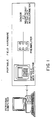
- the system of the present invention is shown schematically in Figure 1.
- the system translates the acoustic/vibratory energy created by industrial processes into useful process-related information.
- Data are typically measured using commercially available transducers (accelerometer, pressure, etc.).
- the preamplifier provides the necessary signal conditioning between the accelerometer and data collector.
- the commercially available data collector performs the necessary frequency domain averaging and temporary data storage.
- the data are ultimately loaded to a computer for analysis and archival storage.
- For fluidized bed units examples are provided demonstrating how the system can provide information on vessel flow uniformity, fluid bed height, mixing uniformity, quality of feed nozzle operation, nozzle steam/feed mixing, and wall coke buildup. This invention enables a non-acoustical expert to easily collect and interpret data.
- the acoustic/vibratory portable analysis system consists of the following components: (1) sensors; (2) a preamplifier; (3) a commercially available data collector; (4) specialized software to translate the vibratory/acoustic data into process related information; and (5) (optional) commercial or customized software to transfer data between the data collector and computer.
- sensors (1) sensors; (2) a preamplifier; (3) a commercially available data collector; (4) specialized software to translate the vibratory/acoustic data into process related information; and (5) (optional) commercial or customized software to transfer data between the data collector and computer.
- Output from the system can be tabular and/or graphical. Depending on the application, results are interpreted on an: absolute basis; relative basis utilizing only the current data; relative basis comparing the current data with previously collected (historical) data.
- Routine data are collected with no prejudice regarding process conditions.
- Special comparison data are collected when the process is in a particular condition (typically immediately after start-up with no known operating problems).
- a diagnostic data type non-historical is also available for conducting "spot checks”.
- An important feature of the system is its capability to manipulate acoustical power spectra: peak finding and area calculation.
- the system's functionality enables a user to modify existing procedures or add new applications in software. Extensive computer expertise is not required to implement such changes.
- the peak finding and area calculation algorithms are based on algorithms developed for vibrational analysis applications.
- a stack oriented calculator is built into the algorithm to facilitate tuning to specific applications. This feature enables extracted power spectra quantities (area, peak amplitude, peak frequency, band width) to be manipulated arithmetically.
- a "learn" mode option allows a user to try out various procedures.
- a shell is built into the system that allows the user full access to such utilities as copy, rename, delete, and other system operations.
- a full screen editor lets the user merge and edit existing procedures or replicate and customize procedure templates.
- Field data from various data collectors are converted to a standard format via independent "plug-compatible" data conversion modules.
- Historical data results are stored in a spreadsheet format that may be used directly or imported easily by commercially available spreadsheet or database programs.
- the system is designed to be a completely self-contained unit for the analysis and reporting of vibrational analysis data that can accept data from various data collectors and can act as the "front-end" to other analysis packages.
- the hardware used in the system of the present invention is described below. However, there are many equivalent acceptable substitutes supplied by many vendors.
- the accelerometers used in the system include B&K 4384 or Endevco 2276.
- the preamplifier is B&K 2634 or B&K 2635.
- the portable data collector is a Palomar 6100, Ono Sokki CF200, or Ono Sokki CF350.
- the personal computer may be a IBM PC/AT, IBM PC/PS2 Model 60, 70 or 80, or compatible unit.
- the commercially available software that is used to operate the present system is ASYST (Version 2.1) and ENTEK Monitor (Version 2.83) (transferring data from data collector to personal computer).
- the system shell is built using ASYST.
- the major analysis features are subsequently described.
- the system can be used in the manual mode by applications personnel for non-routine analysis and research purposes. Once applications have been developed, the system can be used in an automatic mode by operations personnel.
- current fluidized bed systems automated applications include:
- the system captures vibration data by attaching (magnetically, adhesive, screws, etc.) accelerometers to a vessel wall or to the external piping of a feed injection nozzle.
- An accelerometer transforms vibration data into electrical signals.
- the specified accelerometer only measures vibrational energy perpendicular to its face; the types identified do not respond to vibrations parallel to its surface. Data are collected for about two minutes so that the signal can be averaged in order to minimize the impact of data extremes which don't represent true process parameters. Depending on the application, 20-100 ensemble frequency domain averages are sufficient to ensure sufficient statistical accuracy.
- the surface be clean at the measuring location.
- the surface must be free of dirt, rust, and paint.
- the points should be cleaned immediately prior to each set of measurements.
- the points should not be close to mechanical discontinuities such as welds.
- the preamplifier By amplifying the small electrical signal from the accelerometer to a level suitable for use by the data collector, the preamplifier assures electrical compatibility between the accelerometer and data collector. While some signals from the accelerometer are strong enough to drive the data collector without a preamplifier it can not be assured that signals at all frequencies will be treated equivalently. *Fast Fourier Transform
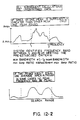
- a fluidized bed reactor system generates vibration signals over a large frequency band, with each vessel and pipe amplifying some frequencies and attenuating others.
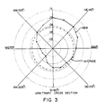
- the thickness and composition of the reactor vessel wall causes a natural acoustical resonance (amplification) in the 5000-10,000 Hz range ( Figure 2).
- Certain applications e.g. reactor bed level, wall coke thickness
- the signal characteristics of particular interest to the system are: 1) the frequency at which the resonance occurs and 2) the acceleration within the frequency limits defined by the resonance band (i.e. the band-limited acceleration).
- the band-limited acceleration is proportional to the area under the resonance peak.
- the best operating mode includes a complete set of reference (comparison) data which are collected when the unit is in an operating state with no know problems. Data collected shortly after a unit start-up would typically meet this criterion. Accordingly, the system specifically accommodates base-case data (denoted herein as comparison data) but does not require it.
- Figure 2 illustrates a typical wall signal as "heard" by the system.
- the band-limited acceleration area under the peak, usually called the wall resonance acceleration
- the measurement of wall coke thickness is based on the frequency associated with the peak amplitude of the wall resonance rather than the actual acceleration level.
- wall resonance acceleration tends to minimize the impact of other extraneous mechanical resonances from the vessel structure.
- wall-resonance acceleration data can be contaminated or obscured by localized mechanical discontinuities, e.g. weld plates, mechanical supports, refractory ties. Therefore, if data from a particular measurement location is significantly different from other data within the measurement series, the specific mechanical structure around that location should be reviewed.
- the system provides a means for evaluating flow uniformity within a vessel.
- this application is often referred to as flow anisotropy evaluation.
- Flow anisotropy is evaluated by conducting wall measurements circumferentially at a vessel cross-section. Typically 8-20 measurement locations are used at each cross-section depending on vessel size. As a rule, the point to point circumferential distance should be limited to approximately 2 meters (6 feet). The number and location of cross-sections are unit dependent, but some typical locations include:
- Figure 3 shows on a polar graph the result of an anisotropy measurement on a coker wall.
- the wall resonance accelerations were computed and plotted on Figure 3 at the correct angular position for 8 positions (measurement locations).
- the dotted circle shows the average result of all eight positions. The average is presented as a guide for the eye to evaluate deviations from the average. It can be shown that the acceleration signals are proportional to the product of the coke particles' volume density and velocity to the 3/2 power. Guidelines, presented below, enable process-related information to be inferred from these data.
- the system generates the type of plot shown in Figure 3.
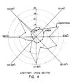
- Figure 4 shows the use of overlayed data in evaluating a FCCU regenerator grid malfunction.
- the system provides this overlay capability to compare the current unit performance with the comparison data set ( Figure 4). Flow patterns which deviate substantially from historical (e.g., comparison) data warrant further investigation.
- unit historical data provide the best evaluation tool.
- some general statistical guidelines may be developed for identifying abnormal operating conditions. A procedure for developing these guidelines is to collect repeated data on a normally operating unit or data on several similar units.
- the system can identify wall coke thickness at each measured circumferential cross-section.
- the guidelines for measurement spacing and cross-section location are identical with those presented for anisotropy measurements.
- the system identifies the resonance frequency, performs the above calculation, and presents coke thickness as a function of position graphically, as shown in Figure 5. Where necessary, the calculation procedure accounts for differences in steel and refractory differences by deck.* As in the case of flow anisotropy, the point-by-point coke thickness in inches or centimeters is compared with the average coke thickness. Comparison of current coke thickness data with historical data also is possible ( Figure 6).
- the procedure for locating bed level is to conduct several measurements vertically on the heater wall. Typically 15-20 measurement positions are required with 6-8 inch spacing, in order to encompass the nominal bed level. Approximately half the points should be below the estimated bed level and half above. Although measurements in a single quadrant are sufficient to determine bed level, repeated tests in other quadrants will account for the effects of vessel anisotropy. Testing in more than one quadrant is recommended.
- Bed level measurements are very susceptible to contamination by small process changes.
- the present system can determine whether or not the changes will adversely affect the bed level determination.
- One point in each quadrant designated as the reference bed level measurement location, is used to confirm steady process conditions during the test period. Measurements at the reference point are conducted at the start and conclusion of the test. This reference location is the bottom most location within each quadrant. The system compares the starting and ending data to confirm process stability over the measurement period.
- the system will compute the wall resonance acceleration at each location and present the data as shown in Figures 7A-B.
- relative acceleration values are more important than actual acceleration.
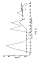
- Figures 8A and 8B demonstrate an example from an injector on a Flexicoker (the measurement location is the injector rodding plug).
- the data in Figure 8A were collected during a condition of steam flow only (e.g. "off” injector), and the Figure 8B data were measured during oil and steam flow (e.g. "on” injector).
- the primary feature to note is the signal increase around 2000 Hz when the oil is turned on.
- the oil signal always occurs lower in frequency than the steam flow signal.
- the oil signal frequency is determined by nozzle size and piping geometry.
- the steam signal frequency is set by the steam restriction orifice size which has a much smaller diameter than the characteristic dimension of the nozzle.
- the system is first used to identify, establish, and verify the kind of relationship demonstrated in Figures 8A and 8B. Typically, this analysis would be done in the manual mode by an application engineer. Once the application is proven and verified, the system can be programmed in the automated mode to compute tables and graphs.
- the frequency range for the oil and steam signals are different for different units, it is reasonably repeatable for feed injectors within a specific unit.
- the oil signal frequency has been between 700-2000 Hz.
- the frequency ranges are functions of feed injector geometry, external injector plumbing, process conditions (steam and oil flow), and feed type. Therefore, the only reliable method for identifying steam and oil signals is to conduct an injector by injector on/off (oil) test.
- the current technology relates the band-limited acceleration of the oil and steam signals to oil and steam flow, respectively. It is known that the two signals are not independent, i.e. changing either steam or oil flow will affect both signal components.
- the oil signal is comparatively less sensitive to steam fluctuations than it is to oil fluctuations.
- the oil signal can be used as a qualitative indicator of injector oil flow conditions.
- the oil signal is not directly proportional to oil flow, it does give an indication of oil/steam mixing and flow.
- steam signals are a qualitative indicator of steam flow.
- Feed injectors are typically connected to a common header.
- the vibrational analysis system enables historical and statistical data to be presented on a per nozzle or per subheader (ring) basis.
- Figure 9A illustrates the "oil signal" data presentation for a particular nozzle. Provisions are included to overlay the comparison data when the nozzle was in a known, good operating condition.
- Figure 9B illustrates how data are presented to facilitate comparison of nozzles on a given oil feed ring.
- Figure 9C shows how the average "oil signal” data for all nozzles on a feed ring are compared.
- the system can also produce tabulated reports of the data shown in Figure 9.
- similar presentations are also available for steam or chugging signals. The singular most important reporting feature is to present injector data in a manner that will facilitate the identification of statistical outliers.
- Bete feed injectors or nozzles are supplied by Bete Fog Nozzle Inc., P.O. Box 31, 324 Wells Street, Greenfield, Massachussetts 01302, U.S.A.
- ASCII is an abbreviation for American Standard Code for Information Interchange.
- ⁇ .CAL; .CHG; .ANI; etc. are computer file designations.
- ⁇ "Overlay” refers to a comparison of sets (e.g. 2 sets) of data on the same graph.
Landscapes
- Chemical & Material Sciences (AREA)
- Engineering & Computer Science (AREA)
- Combustion & Propulsion (AREA)
- Organic Chemistry (AREA)
- Chemical Kinetics & Catalysis (AREA)
- Measurement Of Mechanical Vibrations Or Ultrasonic Waves (AREA)
- Devices And Processes Conducted In The Presence Of Fluids And Solid Particles (AREA)
- Testing And Monitoring For Control Systems (AREA)
Applications Claiming Priority (2)
| Application Number | Priority Date | Filing Date | Title |
|---|---|---|---|
| US07/355,540 US5022268A (en) | 1989-05-22 | 1989-05-22 | Passive acoustics system to monitor fluidized bed systems |
| US355540 | 1989-05-22 |
Publications (3)
| Publication Number | Publication Date |
|---|---|
| EP0399796A2 true EP0399796A2 (fr) | 1990-11-28 |
| EP0399796A3 EP0399796A3 (fr) | 1991-02-27 |
| EP0399796B1 EP0399796B1 (fr) | 1994-03-30 |
Family
ID=23397806
Family Applications (1)
| Application Number | Title | Priority Date | Filing Date |
|---|---|---|---|
| EP90305576A Expired - Lifetime EP0399796B1 (fr) | 1989-05-22 | 1990-05-22 | Dispositif acoustique passif pour surveiller des systèmes à lit fluidifié |
Country Status (7)
| Country | Link |
|---|---|
| US (1) | US5022268A (fr) |
| EP (1) | EP0399796B1 (fr) |
| JP (1) | JP2960111B2 (fr) |
| AU (1) | AU628565B2 (fr) |
| CA (1) | CA2015858C (fr) |
| DE (1) | DE69007676T2 (fr) |
| ES (1) | ES2050952T3 (fr) |
Cited By (3)
| Publication number | Priority date | Publication date | Assignee | Title |
|---|---|---|---|---|
| EP0781596A3 (fr) * | 1995-12-22 | 1998-05-13 | Exxon Research And Engineering Company | Procédé acoustique passif pour surveiller des conduites d'injection de change d'un craqueur catalytique |
| WO2003051929A1 (fr) * | 2001-12-17 | 2003-06-26 | Univation Technologies Llc | Procede d'application d'une dynamique non lineaire pour regler le fonctionnement d'un reacteur de polyethylene en phase gazeuse |
| US7947797B2 (en) | 2005-09-14 | 2011-05-24 | Univation Technologies, Llc | Method for operating a gas-phase reactor at or near maximum production rates while controlling polymer stickiness |
Families Citing this family (25)
| Publication number | Priority date | Publication date | Assignee | Title |
|---|---|---|---|---|
| US5974887A (en) * | 1997-09-26 | 1999-11-02 | Exxon Research And Engineering Co. | Method for determining operating status of liquid phase gas-phase interaction columns |
| US6460412B1 (en) | 2000-10-27 | 2002-10-08 | Union Carbide Chemicals & Plastics Technology Corporation | Detection of dynamic fluidized bed level in a fluidized bed polymerization reactor using ultrasonic waves or microwaves |
| US8512525B2 (en) * | 2001-03-12 | 2013-08-20 | Curtiss-Wright Flow Control Corporation | Valve system and method for unheading a coke drum |
| US8123197B2 (en) | 2001-03-12 | 2012-02-28 | Curtiss-Wright Flow Control Corporation | Ethylene production isolation valve systems |
| US6770032B2 (en) | 2001-12-03 | 2004-08-03 | Microsense Cardiovascular Systems 1996 | Passive ultrasonic sensors, methods and systems for their use |
| US7846736B2 (en) * | 2001-12-17 | 2010-12-07 | Univation Technologies, Llc | Method for polymerization reaction monitoring with determination of entropy of monitored data |
| US8702911B2 (en) | 2003-02-21 | 2014-04-22 | Curtiss-Wright Flow Control Corporation | Center feed system |
| US7316762B2 (en) | 2003-04-11 | 2008-01-08 | Curtiss-Wright Flow Control Corporation | Dynamic flange seal and sealing system |
| US7473337B2 (en) * | 2004-04-22 | 2009-01-06 | Curtiss-Wright Flow Control Corporation | Remotely controlled decoking tool used in coke cutting operations |
| US7117959B2 (en) * | 2004-04-22 | 2006-10-10 | Curtiss-Wright Flow Control Corporation | Systems and methods for remotely determining and changing cutting modes during decoking |
| US8679298B2 (en) | 2004-04-22 | 2014-03-25 | Curtiss-Wright Flow Control Corporation | Remotely controlled decoking tool used in coke cutting operations |
| US20070038393A1 (en) * | 2005-08-12 | 2007-02-15 | Frederic Borah | Vibration monitoring |
| US7819009B2 (en) * | 2006-02-28 | 2010-10-26 | Frederic Borah | Vibration Monitoring System |
| US7931044B2 (en) | 2006-03-09 | 2011-04-26 | Curtiss-Wright Flow Control Corporation | Valve body and condensate holding tank flushing systems and methods |
| US7815775B2 (en) * | 2007-08-27 | 2010-10-19 | Exxonmobil Research & Engineering Company | Optimized coke cutting method for decoking substantially free-flowing coke in delayed cokers |
| US7935226B2 (en) * | 2007-08-29 | 2011-05-03 | Exxonmobil Research And Engineering Company | Method and system to remove coke from a coker drum |
| US8440057B2 (en) | 2008-01-23 | 2013-05-14 | Curtiss-Wright Flow Control Corporation | Linked coke drum support |
| US7871500B2 (en) * | 2008-01-23 | 2011-01-18 | Curtiss-Wright Flow Control Corporation | Coke drum skirt |
| US8545680B2 (en) * | 2009-02-11 | 2013-10-01 | Curtiss-Wright Flow Control Corporation | Center feed system |
| US8851451B2 (en) * | 2009-03-23 | 2014-10-07 | Curtiss-Wright Flow Control Corporation | Non-rising electric actuated valve operator |
| JP2010249710A (ja) * | 2009-04-17 | 2010-11-04 | Chugoku Electric Power Co Inc:The | 聴診装置 |
| US8459608B2 (en) | 2009-07-31 | 2013-06-11 | Curtiss-Wright Flow Control Corporation | Seat and valve systems for use in delayed coker system |
| US9052230B2 (en) * | 2011-05-13 | 2015-06-09 | Chevron U.S.A. Inc | Industrial process monitoring and imaging |
| CN104583122B (zh) | 2012-08-29 | 2017-09-05 | 赫姆洛克半导体运营有限责任公司 | 锥形流化床反应器及其使用方法 |
| US9146169B2 (en) | 2012-11-26 | 2015-09-29 | General Electric Company | Method and system for use in condition monitoring of pressure vessels |
Citations (2)
| Publication number | Priority date | Publication date | Assignee | Title |
|---|---|---|---|---|
| GB2071513A (en) * | 1980-03-11 | 1981-09-23 | Coal Industry Patents Ltd | Fluidised bed system |
| JPS6196317A (ja) * | 1984-10-18 | 1986-05-15 | Ebara Corp | 流動床熱反応炉の制御方法 |
Family Cites Families (2)
| Publication number | Priority date | Publication date | Assignee | Title |
|---|---|---|---|---|
| US4285241A (en) * | 1979-07-13 | 1981-08-25 | Westinghouse Electric Corp. | Method and apparatus for the determination of the mass of an impacting object |
| US4824016A (en) * | 1987-12-10 | 1989-04-25 | Exxon Research And Engineering Company | Acoustic monitoring of two phase feed nozzles |
-
1989
- 1989-05-22 US US07/355,540 patent/US5022268A/en not_active Expired - Lifetime
-
1990
- 1990-05-01 CA CA002015858A patent/CA2015858C/fr not_active Expired - Fee Related
- 1990-05-18 AU AU55720/90A patent/AU628565B2/en not_active Ceased
- 1990-05-22 DE DE69007676T patent/DE69007676T2/de not_active Expired - Fee Related
- 1990-05-22 ES ES90305576T patent/ES2050952T3/es not_active Expired - Lifetime
- 1990-05-22 EP EP90305576A patent/EP0399796B1/fr not_active Expired - Lifetime
- 1990-05-22 JP JP2132420A patent/JP2960111B2/ja not_active Expired - Fee Related
Patent Citations (2)
| Publication number | Priority date | Publication date | Assignee | Title |
|---|---|---|---|---|
| GB2071513A (en) * | 1980-03-11 | 1981-09-23 | Coal Industry Patents Ltd | Fluidised bed system |
| JPS6196317A (ja) * | 1984-10-18 | 1986-05-15 | Ebara Corp | 流動床熱反応炉の制御方法 |
Non-Patent Citations (2)
| Title |
|---|
| CHEMICAL ENGINEERING PROGRESS, vol. 48, no. 9, 1952, pages 455-458; W.W. SHUSTER et al.: "The measurement of fluidization quality" * |
| PATENT ABSTRACTS OF JAPAN, vol. 10, no. 273 (M-518)[2329], 17th September 1986; & JP-A-61 96 317 (EBARA CORP.) 15-05-1986 * |
Cited By (4)
| Publication number | Priority date | Publication date | Assignee | Title |
|---|---|---|---|---|
| EP0781596A3 (fr) * | 1995-12-22 | 1998-05-13 | Exxon Research And Engineering Company | Procédé acoustique passif pour surveiller des conduites d'injection de change d'un craqueur catalytique |
| WO2003051929A1 (fr) * | 2001-12-17 | 2003-06-26 | Univation Technologies Llc | Procede d'application d'une dynamique non lineaire pour regler le fonctionnement d'un reacteur de polyethylene en phase gazeuse |
| US7226789B2 (en) | 2001-12-17 | 2007-06-05 | Unication Technolofies, Llc | Method of applying non-linear dynamics to control a gas-phase polyethylene reactor operability |
| US7947797B2 (en) | 2005-09-14 | 2011-05-24 | Univation Technologies, Llc | Method for operating a gas-phase reactor at or near maximum production rates while controlling polymer stickiness |
Also Published As
| Publication number | Publication date |
|---|---|
| US5022268A (en) | 1991-06-11 |
| EP0399796B1 (fr) | 1994-03-30 |
| JP2960111B2 (ja) | 1999-10-06 |
| DE69007676D1 (de) | 1994-05-05 |
| EP0399796A3 (fr) | 1991-02-27 |
| CA2015858C (fr) | 2000-06-13 |
| ES2050952T3 (es) | 1994-06-01 |
| DE69007676T2 (de) | 1994-07-14 |
| CA2015858A1 (fr) | 1990-11-22 |
| JPH03102225A (ja) | 1991-04-26 |
| AU5572090A (en) | 1990-11-29 |
| AU628565B2 (en) | 1992-09-17 |
Similar Documents
| Publication | Publication Date | Title |
|---|---|---|
| EP0399796B1 (fr) | Dispositif acoustique passif pour surveiller des systèmes à lit fluidifié | |
| AU618662B2 (en) | Passive acoustics process to monitor fluidized bed flow | |
| EP0385788B1 (fr) | Méthode acoustique passive de surveillance du niveau d'un lit fluidifié | |
| Wei et al. | Profiles of particle velocity and solids fraction in a high-density riser | |
| RU2289836C2 (ru) | Способ применения нелинейной динамики для контроля работоспособности газофазного реактора, предназначенного для получения полиэтилена | |
| US5652145A (en) | Passive acoustics process to monitor feed injection lines of a catalytic cracker (law077) | |
| US4213183A (en) | System for nondestructive evaluation of material flaw characteristics | |
| Cai et al. | Application of chaos theory in identification of two-phase flow patterns and transitions in a small, horizontal, rectangular channel | |
| US20070038393A1 (en) | Vibration monitoring | |
| WO2000043118A1 (fr) | Procede de detection et de controle des changements de proprietes de solides a lit fluidise par mesure de la variation des differences de pression | |
| EP0781597B1 (fr) | Procédé acoustique passif pour surveiller des conduites de transfert d'un réacteur | |
| US5435972A (en) | Fluidization quality analyzer for fluidized beds | |
| CN111693411A (zh) | 一种移动床径向反应器状态检测及故障诊断的方法及装置 | |
| US2984542A (en) | Carbon level analyzer | |
| Khadka | Multiphase flow estimation using accelerometers, ultrasonic sensors, and machine learning | |
| JPS60105994A (ja) | ノイズ監視装置 | |
| Rodrigues et al. | Acousto-Ultrasonic Inspection of Pre-baked Carbon Anodes: Repeatability Analysis and Assessment of Damage Detection Performance | |
| Edelmann et al. | Functions and structure of the Karlsruhe subassembly monitoring system KASUMOS | |
| Ostermier | Zirconium hydride reactor core hydraulic studies: summary report | |
| Chen et al. | Nonlinear Dynamic Analysis of the Local Heat Transfer Rate in Three-Phase Reactors |
Legal Events
| Date | Code | Title | Description |
|---|---|---|---|
| PUAI | Public reference made under article 153(3) epc to a published international application that has entered the european phase |
Free format text: ORIGINAL CODE: 0009012 |
|
| AK | Designated contracting states |
Kind code of ref document: A2 Designated state(s): DE ES FR GB IT NL |
|
| PUAL | Search report despatched |
Free format text: ORIGINAL CODE: 0009013 |
|
| AK | Designated contracting states |
Kind code of ref document: A3 Designated state(s): DE ES FR GB IT NL |
|
| 17P | Request for examination filed |
Effective date: 19910827 |
|
| 17Q | First examination report despatched |
Effective date: 19920207 |
|
| GRAA | (expected) grant |
Free format text: ORIGINAL CODE: 0009210 |
|
| AK | Designated contracting states |
Kind code of ref document: B1 Designated state(s): DE ES FR GB IT NL |
|
| REF | Corresponds to: |
Ref document number: 69007676 Country of ref document: DE Date of ref document: 19940505 |
|
| ET | Fr: translation filed | ||
| ITF | It: translation for a ep patent filed |
Owner name: MODIANO & ASSOCIATI S.R.L. |
|
| REG | Reference to a national code |
Ref country code: ES Ref legal event code: FG2A Ref document number: 2050952 Country of ref document: ES Kind code of ref document: T3 |
|
| PLBE | No opposition filed within time limit |
Free format text: ORIGINAL CODE: 0009261 |
|
| STAA | Information on the status of an ep patent application or granted ep patent |
Free format text: STATUS: NO OPPOSITION FILED WITHIN TIME LIMIT |
|
| 26N | No opposition filed | ||
| REG | Reference to a national code |
Ref country code: GB Ref legal event code: IF02 |
|
| PGFP | Annual fee paid to national office [announced via postgrant information from national office to epo] |
Ref country code: GB Payment date: 20030401 Year of fee payment: 14 |
|
| PGFP | Annual fee paid to national office [announced via postgrant information from national office to epo] |
Ref country code: NL Payment date: 20030403 Year of fee payment: 14 |
|
| PGFP | Annual fee paid to national office [announced via postgrant information from national office to epo] |
Ref country code: FR Payment date: 20030505 Year of fee payment: 14 |
|
| PGFP | Annual fee paid to national office [announced via postgrant information from national office to epo] |
Ref country code: ES Payment date: 20030522 Year of fee payment: 14 |
|
| PGFP | Annual fee paid to national office [announced via postgrant information from national office to epo] |
Ref country code: DE Payment date: 20030530 Year of fee payment: 14 |
|
| PG25 | Lapsed in a contracting state [announced via postgrant information from national office to epo] |
Ref country code: GB Free format text: LAPSE BECAUSE OF NON-PAYMENT OF DUE FEES Effective date: 20040522 |
|
| PG25 | Lapsed in a contracting state [announced via postgrant information from national office to epo] |
Ref country code: ES Free format text: LAPSE BECAUSE OF NON-PAYMENT OF DUE FEES Effective date: 20040524 |
|
| PG25 | Lapsed in a contracting state [announced via postgrant information from national office to epo] |
Ref country code: NL Free format text: LAPSE BECAUSE OF NON-PAYMENT OF DUE FEES Effective date: 20041201 Ref country code: DE Free format text: LAPSE BECAUSE OF NON-PAYMENT OF DUE FEES Effective date: 20041201 |
|
| GBPC | Gb: european patent ceased through non-payment of renewal fee |
Effective date: 20040522 |
|
| PG25 | Lapsed in a contracting state [announced via postgrant information from national office to epo] |
Ref country code: FR Free format text: LAPSE BECAUSE OF NON-PAYMENT OF DUE FEES Effective date: 20050131 |
|
| NLV4 | Nl: lapsed or anulled due to non-payment of the annual fee |
Effective date: 20041201 |
|
| REG | Reference to a national code |
Ref country code: FR Ref legal event code: ST |
|
| PG25 | Lapsed in a contracting state [announced via postgrant information from national office to epo] |
Ref country code: IT Free format text: LAPSE BECAUSE OF NON-PAYMENT OF DUE FEES;WARNING: LAPSES OF ITALIAN PATENTS WITH EFFECTIVE DATE BEFORE 2007 MAY HAVE OCCURRED AT ANY TIME BEFORE 2007. THE CORRECT EFFECTIVE DATE MAY BE DIFFERENT FROM THE ONE RECORDED. Effective date: 20050522 |
|
| REG | Reference to a national code |
Ref country code: ES Ref legal event code: FD2A Effective date: 20040524 |