EP0399357B1 - Device for cleaning clogged drains - Google Patents
Device for cleaning clogged drains Download PDFInfo
- Publication number
- EP0399357B1 EP0399357B1 EP90109228A EP90109228A EP0399357B1 EP 0399357 B1 EP0399357 B1 EP 0399357B1 EP 90109228 A EP90109228 A EP 90109228A EP 90109228 A EP90109228 A EP 90109228A EP 0399357 B1 EP0399357 B1 EP 0399357B1
- Authority
- EP
- European Patent Office
- Prior art keywords
- valve
- retaining ring
- aerosol
- protective cap
- adapter
- Prior art date
- Legal status (The legal status is an assumption and is not a legal conclusion. Google has not performed a legal analysis and makes no representation as to the accuracy of the status listed.)
- Expired - Lifetime
Links
Images
Classifications
-
- B—PERFORMING OPERATIONS; TRANSPORTING
- B65—CONVEYING; PACKING; STORING; HANDLING THIN OR FILAMENTARY MATERIAL
- B65D—CONTAINERS FOR STORAGE OR TRANSPORT OF ARTICLES OR MATERIALS, e.g. BAGS, BARRELS, BOTTLES, BOXES, CANS, CARTONS, CRATES, DRUMS, JARS, TANKS, HOPPERS, FORWARDING CONTAINERS; ACCESSORIES, CLOSURES, OR FITTINGS THEREFOR; PACKAGING ELEMENTS; PACKAGES
- B65D83/00—Containers or packages with special means for dispensing contents
- B65D83/14—Containers or packages with special means for dispensing contents for delivery of liquid or semi-liquid contents by internal gaseous pressure, i.e. aerosol containers comprising propellant for a product delivered by a propellant
- B65D83/16—Containers or packages with special means for dispensing contents for delivery of liquid or semi-liquid contents by internal gaseous pressure, i.e. aerosol containers comprising propellant for a product delivered by a propellant characterised by the actuating means
- B65D83/20—Containers or packages with special means for dispensing contents for delivery of liquid or semi-liquid contents by internal gaseous pressure, i.e. aerosol containers comprising propellant for a product delivered by a propellant characterised by the actuating means operated by manual action, e.g. button-type actuator or actuator caps
-
- B—PERFORMING OPERATIONS; TRANSPORTING
- B05—SPRAYING OR ATOMISING IN GENERAL; APPLYING FLUENT MATERIALS TO SURFACES, IN GENERAL
- B05B—SPRAYING APPARATUS; ATOMISING APPARATUS; NOZZLES
- B05B1/00—Nozzles, spray heads or other outlets, with or without auxiliary devices such as valves, heating means
- B05B1/005—Nozzles or other outlets specially adapted for discharging one or more gases
-
- B—PERFORMING OPERATIONS; TRANSPORTING
- B65—CONVEYING; PACKING; STORING; HANDLING THIN OR FILAMENTARY MATERIAL
- B65D—CONTAINERS FOR STORAGE OR TRANSPORT OF ARTICLES OR MATERIALS, e.g. BAGS, BARRELS, BOTTLES, BOXES, CANS, CARTONS, CRATES, DRUMS, JARS, TANKS, HOPPERS, FORWARDING CONTAINERS; ACCESSORIES, CLOSURES, OR FITTINGS THEREFOR; PACKAGING ELEMENTS; PACKAGES
- B65D83/00—Containers or packages with special means for dispensing contents
- B65D83/14—Containers or packages with special means for dispensing contents for delivery of liquid or semi-liquid contents by internal gaseous pressure, i.e. aerosol containers comprising propellant for a product delivered by a propellant
- B65D83/16—Containers or packages with special means for dispensing contents for delivery of liquid or semi-liquid contents by internal gaseous pressure, i.e. aerosol containers comprising propellant for a product delivered by a propellant characterised by the actuating means
- B65D83/22—Containers or packages with special means for dispensing contents for delivery of liquid or semi-liquid contents by internal gaseous pressure, i.e. aerosol containers comprising propellant for a product delivered by a propellant characterised by the actuating means with a mechanical means to disable actuation
-
- E—FIXED CONSTRUCTIONS
- E03—WATER SUPPLY; SEWERAGE
- E03C—DOMESTIC PLUMBING INSTALLATIONS FOR FRESH WATER OR WASTE WATER; SINKS
- E03C1/00—Domestic plumbing installations for fresh water or waste water; Sinks
- E03C1/12—Plumbing installations for waste water; Basins or fountains connected thereto; Sinks
- E03C1/30—Devices to facilitate removing of obstructions in waste-pipes or sinks
Definitions
- the invention is directed to a device for cleaning clogged drain pipes, particularly in the household, consisting of a conventional aerosol can with a pin-shaped outlet valve plugged onto the flanging of the can and a protective cap overlapping the valve area for actuating the valve with a sealing area for conventional ones Drainage screens and a releasable actuation lock for the valve, the protective cap having a central outlet opening with means for depressing the valve pin, the outlet pin tightly encompassing the valve pin, retaining elements engaging in a clamping bead of the valve and guide elements supporting on the outside of the aerosol can.
- Such a device has become known, for example, from the Austrian patent AT-B-362319.
- This device is filled with a pressurized, non-toxic and non-combustible gas.
- the device is inserted in the approximately vertical overhead position with the protective cap in the drain strainer of the sink or the like.
- the protective cap and the aerosol can are displaceable relative to one another in the vertical direction, so that the valve then opens by depressing the aerosol can and the gas in the can escapes.
- the escaping gas jet creates pressure on the blocked drain line standing water column, which presses the water column into the drain pipe and thereby eliminates the blockage.
- the disadvantage is that the known device is not refillable. In addition, a reliably working, more user-friendly actuation lock would be desirable.
- the object of the invention is to improve the above-mentioned device in such a way that it can be refilled with an environmentally friendly propellant and is provided with a handling-friendly actuation lock.
- this object is achieved according to the invention in that the aerosol can is filled with compressed air and for refilling the area of the protective cap comprising the valve pin is extended as a free-standing cylindrical adapter and the actuation lock can be released by relative rotation of the aerosol can and protective cap .
- the invention provides in an expedient embodiment that the adapter for detection can be freely gripped with conventional tire air pressure testing and filling devices is arranged within a funnel-shaped indentation in the protective cap.
- actuation lock consists of a cup-shaped retaining ring fastened to the clamping bead of the valve with regularly distributed, vertical incisions in its circumferential wall and a cylinder element which can be moved vertically and circumferentially relative to the latter exists, which is attached to the inner surface of the protective cap and is provided with webs or cams corresponding to the incisions of the retaining ring, the valve being open when the webs or cams engage in the incisions of the retaining ring and when the webs or cams rest on the edge of the retaining ring the valve cannot be opened.
- the position in which the valve can be opened is advantageously indicated to the user by snapping the webs or cams into the incisions, which limits further relative rotation of the protective cap and aerosol can.
- finding the open position for the user is made even easier by the fact that the retaining ring and the cylinder element relative to one another in the vertical direction by a distance that corresponds to the depth of the incisions and in the circumferential direction by a distance that is smaller than the distance between two incisions are movable, as the invention provides in further training.
- the retaining ring it is particularly advantageous for the retaining ring to hold the retaining elements which grip the clamping bead of the valve and areas with radially protruding outwards Has projections which protrude into window-shaped recesses of the cylinder element bearing with its inner wall against the outer wall of the retaining ring and the maximum possible relative movement between the retaining ring and the cylinder element is limited by abutment against the window border.
- the invention further provides in a user-friendly design that the projections are arranged in the window-shaped recesses in such a way that the valve can be actuated clockwise after a relative rotation of the aerosol can.
- the invention is further characterized in that a bevel is formed adjacent to the incisions on the edge of the retaining ring.
- an annular bead is formed in the upper area on the outer surface of the adapter.
- the bead seals the adapter to the part of the refilling device to be fitted.
- this bead can also be made of wear-and-tear material that wears out a little during each refill process. After a certain number of refilling operations, the bead then no longer seals, so that refilling is no longer possible. This is then an indication to the user that the device should not be used for safety reasons.
- the invention provides that two to six longitudinal slots are formed in the bead and / or in the outer surface of the adapter on the circumference. Through these longitudinal slots, part of the compressed air can flow past the outside of the adapter when the tire inflation device is attached to the adapter. This ensures that the aerosol can can only be filled up to a certain can pressure. This avoids misuse by operating the tire inflator for too long and possibly causing the can pressure to be too high.
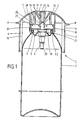
- the device designated as 1 overall in FIG. 1 for cleaning clogged drain pipes consists of a conventional aerosol can 2 and a protective cap 3.
- the opening edge of the aerosol can 2 has a flange 4 which is customary in aerosol cans.
- a valve plate 5 with a central, pin-shaped valve 6 is clipped onto this flange 4.
- it is a usual aerosol can, for example an tin-plated tin can, designed for a test pressure of 15 bar.
- the protective cap 3 has an area 7 that overlaps the entire aerosol can cross section, including the valve area, and is curved outwards.
- annular sealing flange 8 is formed as a sealing area with respect to conventional drain screens.
- the curvature area 7 and the sealing flange 8 are designed overall such that the curvature area is placed on conventional drain strainers or can be inserted into them until the sealing flange 8 seals comes to rest on the edge of the respective drain strainer, which is usually cup-shaped.
- the further outer region of the protective cap 3 adjoining the ring flange 8 is cylindrical. On its inside, this cylindrical region 9 has web-shaped guide elements 10 which rest on the outer wall of the aerosol can 2.
- a funnel-shaped indentation 11 is formed centrally in the arched region 7 of the protective cap 3, with a cylindrical region 14 that surrounds the outlet opening 12 and lies closely against the pin-shaped outlet 13 of the valve 6 protruding from the valve disk 5.
- the inner wall of the area 14 protrudes inwards to form the outlet opening 12 and to form an annular stop area 15.
- the valve pin 13 bears against this stop area 15, so that means for depressing the valve pin 13 and thus for opening the valve 6 are thereby formed.
- the cylindrical region 14 arranged at the bottom of the funnel-shaped indentation 11 is extended as a cylindrical adapter 16 projecting into the indentation 11.
- the adapter 16 projects as a free-standing hollow cylinder into the funnel-shaped indentation 11 and ends just below the outer surface of the protective cap 3.
- the adapter 16 is dimensioned such that it can be detected with conventional tire air pressure testing and filling devices and through it the aerosol can can be refilled with compressed air .
- the adapter 16 In its upper edge area, has on its outer surface an annular bead 17 for sealing against a refill device that is attached.
- the annular bead 17 expediently consists of a material which wears out over time after repeated placement of a refilling device.
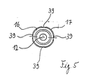
- FIG. 5 shows a top view of a special adapter 16 which, in addition to the bead 17, has four longitudinal slots 39 distributed around the circumference by 90 ° in each case. These longitudinal slots 39 are formed in the bead 17.
- the longitudinal slots 39 have a radius of 0.5-5 mm in width. These longitudinal slots ensure that the bead 17 does not seal completely when the air refill device is placed on the adapter 16, so that part of the compressed air can flow past the adapter through the longitudinal slots 39. This prevents a pressure from being set in the aerosol can 2 which is above the permissible filling pressure in the event of incorrect use.
- only a certain internal can pressure can be set.
- the number of slots and their radius is set so that the internal pressure of the can is preferably 4-8 bar.
- the retaining ring 18 has an intermediate base 19 with a central opening 20 for the valve 6. With the underside of the intermediate floor 19, the retaining ring 18 rests on the flange 4 of the aerosol can 2 or on the region of the valve plate 5 comprising this flange 4 and, with the retaining elements 21 designed as retaining claws in extension of its side wall, detects the clamping bead 22 of the valve 6, which is formed in the area of the flange 4.
- the retaining ring 18 thus forms with its retaining elements 21 the retaining elements of the protective cap 3 which engage in the clamping bead 22 of the valve and, in conjunction with the second component of the actuation lock described below, ensures that the protective cap 3 is securely held on the aerosol can 2.
- the circumferential wall 25 of the cup-shaped retaining ring 18 has vertical incisions 23 distributed regularly over the circumference, which start from the edge 26 of the peripheral wall 25. Furthermore, regions with projections 24 projecting radially outward from the peripheral wall 25 are formed just above the intermediate base 19. Furthermore, the peripheral wall 25 of the retaining ring 18 has a bevel 27 on its edge 26 adjacent to the incisions 23.
- a cylinder element 28 which is fastened centrally outside the funnel-shaped indentation 11 to the inner surface of the curved area 7.
- the cylinder element 28 extends into the area of the flange 4 inward of the cap, the inner surface of the cylinder element 28 abutting the outer surface of the peripheral wall 25 of the cup-shaped retaining ring 18.
- the cylinder element 28 has window-shaped recesses 29 or openings through which the projections 24 of the holding ring 18 protrude.
- the window-shaped openings 29 are larger than the extension areas of the projections 24, so that the projections 24 can be moved in the openings 29 in the vertical and circumferential directions. Furthermore, protruding webs 30 or cams are formed on the inner surface of the cylinder element 28, which corresponding to the vertical incisions 23 of the retaining ring 18 are evenly distributed on the circumference and can be brought into engagement with the incisions 23.
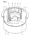
- FIG. 2 shows the protective cap 3 in an enlarged and cut view. It can be seen from FIG. 2 that the webs 30 end at such a distance from the lower edge 31 of the window-like openings 29 that their underside when the projections 24 stop on the lower edge 31 of the window-like openings Opening 29 can slide straight along the edge 26 of the peripheral wall 25 of the retaining ring 18.
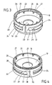
- FIGS. 3 and 4 show the relevant areas of the retaining ring 18 and the cylinder element 28.
- Figure 3 shows the position in which the protective cap 3 can not be pressed down and thus the valve 6 can not be opened.
- the upper region of the retaining ring 18 and the lower region of the cylinder element 28 are shown in FIG. 3, the latter being shown in section just above the lower end of the webs 30.
- the underside of the webs 30 rests on the edge 26 and the underside of the projections 24 rests on the lower edge 31 of the window opening 29.
- a stop point for the vertical relative movement of the cylinder element 28 and retaining ring 18 relative to one another is determined by the abutment of the projections 24 on the edge 31. It is clearly visible that the window-like openings 29 extend over a significantly larger area than the projections 24. From this stop position shown in FIG. 3, the projections 24 can now be displaced in the vertical and circumferential directions by relative movement of the holding ring 18 and the cylinder element 28 .
- the retaining ring 18 and the cylinder element 28 can be rotated relative to one another by rotating the retaining ring 18 in a clockwise direction - which corresponds to a rotation of the aerosol can in a clockwise direction due to the clamping fastening of the retaining ring 18 on the aerosol can 2 achieve.
- the projections 24 slide along the lower edge 31 of the recesses 29 and the undersides of the webs 30 along the edge 26 of the peripheral wall 25.
- the webs 30 then arrive by way of this relative rotation in the area of the bevels 27, which causes a first vertical relative movement of the cylinder element 28 and the retaining ring 18 to one another.
- an actuation lock is created by the mutually movable arrangement of cylinder element 28 and retaining ring 18 and the corresponding configurations of projections 24 and window-like openings 29, as well as webs 30 and notches 23, in which the retaining ring 18 and cylinder element 28 move in the vertical direction by a distance that the depth of the incisions 23 corresponds and can be moved in the circumferential direction by a distance which is smaller than the distance between two incisions, relative to one another.
- the latter can also be seen in FIG. 3, since here the projections 24 already strike the side edge 38 of the window-like openings 29 when the webs 30 have not even covered half the distance between two incisions 23.
- the protective cap 3 is preferably made of plastic and is made in one piece except for the retaining ring 18.
- the aerosol can is filled with compressed air and can be refilled with the usual refill devices through the adapter.
- the preferably provided filling pressure for the device described above is 3 bar.
- a securing element for example in the form of a tear strip, connecting the cylinder element 28 and the retaining ring 18 can also be provided, which prevents a relative movement of the retaining ring 18 and the cylinder element 28 from one another until it is removed, and thus serves in particular to secure the transportation.
- the device described above is moved from the shut-off position according to FIG. 3 into the position in which the side surfaces 32 of the projections 24 strike the edge 33 of the window-like opening 29.
- the device is then placed in the overhead position with the curved area 7 as vertically as possible over the drain strainer of the blocked drain pipe.
- the aerosol can is then depressed, so that there is a vertical or relative axial movement with respect to the longitudinal axis of the aerosol can between the aerosol can and the protective cap 3 and the protective cap is moved into the opening or release position of the valve 6 according to FIG. 4.
- the compressed air By the now flowing out of the pressurized aerosol can 2 compressed air and due to the sealing of the curved area 7 or the annular flange 8 against the edge of the drain strainer, the compressed air now exerts a pressure on the water column in the blocked drain pipe. If the pressure is high enough, the water column is pressed into the drain pipe and the blockage is removed. The aerosol can is then released and there is again a relative movement of the aerosol can 2 and protective cap 3 or of the holding ring 18 and cylinder element 28 first in the vertical and then in the circumferential direction until the locking position corresponding to FIG. 3 is reached.
- the protective cap 3 and aerosol can 2 are moved to one another in a position in which the side surfaces 32 of the projections 24 abut the side edges 33 of the window-like openings 29. Then, for example, the refill of conventional tire air pressure testing and filling devices is placed on the adapter 16 and the protective cap 3 is pressed down. In this position, the aerosol can 2 can then be refilled with compressed air through the adapter 16, the opening 12 and the valve pin 13. After this filling process, the protective cap 3 is moved back into the shut-off position according to FIG. 3.
Abstract
Description
Die Erfindung richtet sich auf eine Vorrichtung zur Reinigung von verstopften Abflußrohren, insbesondere im Haushaltsbereich, bestehend aus einer üblichen Aerosoldose mit auf die Bördelung der Dose aufgestecktem, stiftförmigem Auslaßventil und einer den Ventilbereich überfangenden, nach außen gewölbten Schutzkappe zur Betätigung des Ventiles mit Abdichtbereich für übliche Abflußsiebe und einer lösbaren Betätigungssperre für das Ventil, wobei die Schutzkappe eine zentrale, den Ventilstift eng umfassende Austrittsöffnung mit Mitteln zum Niederdrücken des Ventilstiftes, in eine Klemmsicke des Ventils eingreifende Halteelemente und sich auf der Außenseite der Aerosoldose abstützende Führungselemente aufweist.The invention is directed to a device for cleaning clogged drain pipes, particularly in the household, consisting of a conventional aerosol can with a pin-shaped outlet valve plugged onto the flanging of the can and a protective cap overlapping the valve area for actuating the valve with a sealing area for conventional ones Drainage screens and a releasable actuation lock for the valve, the protective cap having a central outlet opening with means for depressing the valve pin, the outlet pin tightly encompassing the valve pin, retaining elements engaging in a clamping bead of the valve and guide elements supporting on the outside of the aerosol can.
Eine derartige Vorrichtung ist beispielsweise durch die österreichische Patentschrift AT-B-362319 bekanntgeworden. Diese Vorrichtung ist mit einem unter Druck stehenden, ungiftigen und nichtbrennbaren Gas befüllt. Zur Reinigung von verstopften Abflüssen wird die Vorrichtung in annähernd senkrechter Überkopfstellung mit der Schutzkappe in das Abflußsieb von Waschbecken oder dergleichen gesteckt. Die Schutzkappe und die Aerosoldose sind in vertikaler Richtung relativ gegeneinander verschiebbar, so daß anschließend durch Niederdrücken der Aerosoldose das Ventil öffnet und das in der Dose befindliche Gas entweicht. Durch den entweichenden Gasstrahl wird ein Druck auf die in der verstopften Abflußleitung stehende Wassersäule ausgeübt, der die Wassersäule in das Abflußrohr drückt und dadurch die Verstopfung beseitigt.Such a device has become known, for example, from the Austrian patent AT-B-362319. This device is filled with a pressurized, non-toxic and non-combustible gas. To clean clogged drains, the device is inserted in the approximately vertical overhead position with the protective cap in the drain strainer of the sink or the like. The protective cap and the aerosol can are displaceable relative to one another in the vertical direction, so that the valve then opens by depressing the aerosol can and the gas in the can escapes. The escaping gas jet creates pressure on the blocked drain line standing water column, which presses the water column into the drain pipe and thereby eliminates the blockage.
Von Nachteil ist, daß die bekannte Vorrichtung nicht nachfüllbar ist. Außerdem wäre eine zuverlässig arbeitende, handhabungsfreundlichere Betätigungssperre wünschenswert.The disadvantage is that the known device is not refillable. In addition, a reliably working, more user-friendly actuation lock would be desirable.
Aufgabe der Erfindung ist es, die eingangs genannte Vorrichtung dahingehend zu verbessern, daß sie mit einem umweltfreundlichen Treibmittel wiederbefüllbar und mit einer handhabungsfreundlichen Betätigungssperre versehen ist.The object of the invention is to improve the above-mentioned device in such a way that it can be refilled with an environmentally friendly propellant and is provided with a handling-friendly actuation lock.
Bei einer Vorrichtung der eingangs bezeichneten Art wird diese Aufgabe gemäß der Erfindung dadurch gelöst, daß die Aerosoldose mit Preßluft gefüllt und zu ihrer Wiederbefüllung der den Ventilstift umfassende Bereich der Schutzkappe als freistehender zylinderförmiger Adapter verlängert ist und die Betätigungssperre durch Relativverdrehung von Aerosoldose und Schutzkappe lösbar ist.In a device of the type mentioned, this object is achieved according to the invention in that the aerosol can is filled with compressed air and for refilling the area of the protective cap comprising the valve pin is extended as a free-standing cylindrical adapter and the actuation lock can be released by relative rotation of the aerosol can and protective cap .
Hierdurch wird eine verbesserte Vorrichtung zur Reinigung von verstopften Abflußrohren geschaffen, die aufgrund der durch Relativverdrehung lösbaren Betätigungssperre handhabungsfreundlich und bequem benutzbar ist und die aufgrund des an der Schutzkappe angeordneten freistehenden zylinderförmigen Adapters problemlos mit dem umweltfreundlichen Treibmittel Preßluft wiederbefüllbar ist.This creates an improved device for cleaning clogged drain pipes, which is easy to use and convenient to use due to the releasable actuation lock and which can be easily refilled with the environmentally friendly propellant compressed air due to the free-standing cylindrical adapter arranged on the protective cap.
Zur bequemen Nachfüllung von Treibmittel sieht die Erfindung in zweckmäßiger Ausgestaltung vor, daß der Adapter für die Erfassung mit üblichen Reifenluftdruckprüf- und -füllgeräten frei umgreifbar innerhalb einer trichterförmigen Einbuchtung in der Schutzkappe angeordnet ist.For convenient refilling of propellant, the invention provides in an expedient embodiment that the adapter for detection can be freely gripped with conventional tire air pressure testing and filling devices is arranged within a funnel-shaped indentation in the protective cap.
Eine besonders bequeme und bedienungsfreundlich handhabbare Betätigungssperre wird gemäß weiterer Ausgestaltung der Erfindung dadurch erhalten, daß die Betätigungssperre aus einem topfförmigen, an der Klemmsicke des Ventils befestigten Haltering mit regelmäßig verteilten, vertikalen Einschnitten in seiner Umfangswand und einem relativ zu diesem vertikal und in Umfangsrichtung bewegbaren Zylinderelement besteht, welches an der Innenfläche der Schutzkappe befestigt und mit zu den Einschnitten des Halterings korrespondierenden Stegen oder Nocken versehen ist, wobei bei rastendem Eingriff der Stege oder Nocken in den Einschnitten des Halteringes das Ventil geöffnet ist und bei Auflage der Stege oder Nocken auf dem Rand des Halteringes das Ventil nicht zu öffnen ist.A particularly convenient and easy-to-use actuation lock is obtained according to a further embodiment of the invention in that the actuation lock consists of a cup-shaped retaining ring fastened to the clamping bead of the valve with regularly distributed, vertical incisions in its circumferential wall and a cylinder element which can be moved vertically and circumferentially relative to the latter exists, which is attached to the inner surface of the protective cap and is provided with webs or cams corresponding to the incisions of the retaining ring, the valve being open when the webs or cams engage in the incisions of the retaining ring and when the webs or cams rest on the edge of the retaining ring the valve cannot be opened.
Hierbei wird dem Benutzer durch das Einrasten der Stege oder Nokken in die Einschnitte, wodurch eine weitere Relativverdrehung von Schutzkappe und Aerosoldose begrenzt ist, in vorteilhafter Weise die Stellung angezeigt, in der das Ventil zu öffnen ist.The position in which the valve can be opened is advantageously indicated to the user by snapping the webs or cams into the incisions, which limits further relative rotation of the protective cap and aerosol can.
Weiterhin wird das Auffinden der Öffnungsstellung für den Benutzer noch dadurch vereinfacht, daß der Haltering und das Zylinderelement in vertikaler Richtung um eine Strecke, die der Tiefe der Einschnitte entspricht, und in Umfangsrichtung um eine Strecke die kleiner als der Abstand zweier Einschnitte ist, relativ zueinander bewegbar sind, wie dies die Erfindung in Weiterbildung vorsieht.Furthermore, finding the open position for the user is made even easier by the fact that the retaining ring and the cylinder element relative to one another in the vertical direction by a distance that corresponds to the depth of the incisions and in the circumferential direction by a distance that is smaller than the distance between two incisions are movable, as the invention provides in further training.
Besonders vorteilhaft ist hierfür gemäß weiterer Ausgestaltung der Erfindung, daß der Haltering die Klemmsicke des Ventils klemmend erfassende Halteelemente sowie Bereiche mit radial nach außen hervorstehenden Vorsprüngen aufweist, die in fensterförmige Ausnehmungen des mit seiner Innenwandung an der Außenwandung des Halteringes anliegenden Zylinderelementes hineinragen und durch Anschlag an die Fensterumrandung die maximal mögliche Relativbewegung zwischen Haltering und Zylinderelement begrenzt ist.According to a further embodiment of the invention, it is particularly advantageous for the retaining ring to hold the retaining elements which grip the clamping bead of the valve and areas with radially protruding outwards Has projections which protrude into window-shaped recesses of the cylinder element bearing with its inner wall against the outer wall of the retaining ring and the maximum possible relative movement between the retaining ring and the cylinder element is limited by abutment against the window border.
Da im täglichen Leben von Hand durchführbare Schraub- oder Rotationsbewegungen üblicherweise im Uhrzeigersinn erfolgen, sieht die Erfindung in benutzerfreundlicher Ausgestaltung weiterhin vor, daß die Vorsprünge derart in den fensterförmigen Ausnehmungen angeordnet sind, daß das Ventil nach einer Relativdrehung der Aerosoldose im Uhrzeigersinn zu betätigen ist.Since in everyday life manual screw or rotary movements usually take place in a clockwise direction, the invention further provides in a user-friendly design that the projections are arranged in the window-shaped recesses in such a way that the valve can be actuated clockwise after a relative rotation of the aerosol can.
Um das Heraus- bzw. Hereinführen der Stege oder Nocken des Zylinderringes in die Einschnitte des Halteringes zu erleichtern, zeichnet sich die Erfindung weiterhin dadurch aus, daß auf dem Rand des Halteringes an die Einschnitte angrenzend jeweils eine Abschrägung ausgebildet ist.In order to facilitate the removal or insertion of the webs or cams of the cylinder ring into the incisions of the retaining ring, the invention is further characterized in that a bevel is formed adjacent to the incisions on the edge of the retaining ring.
Des weiteren sieht die Erfindung in Weiterbildung vor, daß im oberen Bereich an der Außenfläche des Adapters ein ringförmiger Wulst ausgebildet ist. Bei Nachfüllung der erfindungsgemäßen Vorrichtung mit Preßluft aus üblichen Reifenluftdruckprüfgeräten sorgt der Wulst für eine Abdichtung des Adapters zu dem aufzusetzenden Teil des Nachfüllgerätes. Um aus Sicherheitsgründen ein zu häufiges Nachfüllen der erfindungsgemäßen Vorrichtung bzw. ein zu langes Ingebrauchhalten der Vorrichtung zu vermeiden, kann dieser Wulst auch aus sich abnutzendem Material ausgebildet sein, das sich bei jedem Nachfüllvorgang ein wenig abnutzt. Nach einer bestimmten Anzahl von Nachfüllvorgängen dichtet der Wulst dann nicht mehr ab, so daß ein Nachfüllen nicht mehr möglich ist. Dies ist für den Benutzer dann ein Hinweis darauf, daß die Vorrichtung aus Sicherheitsgründen nicht weiterbenutzt werden sollte.Furthermore, the invention provides in a further development that an annular bead is formed in the upper area on the outer surface of the adapter. When the device according to the invention is refilled with compressed air from conventional tire air pressure testing devices, the bead seals the adapter to the part of the refilling device to be fitted. In order to prevent the device according to the invention from being refilled too often or the device from being used for too long, this bead can also be made of wear-and-tear material that wears out a little during each refill process. After a certain number of refilling operations, the bead then no longer seals, so that refilling is no longer possible. This is then an indication to the user that the device should not be used for safety reasons.
Schließlich sieht die Erfindung vor, daß in der Wulst und/oder in der Außenfläche des Adapters auf dem Umfang verteilt zwei bis sechs Längsschlitze ausgebildet sind. Durch diese Längsschlitze kann bei auf dem Adapter aufgesetzten Reifenfüllgerät ein Teil der Preßluft außen am Adapter vorbeiströmen. Hierdurch wird erreicht, daß die Aerosoldose nur bis zu einem bestimmten Doseninnendruck gefüllt werden kann. Dies vermeidet Fehlanwendungen durch zu langes Betätigen des Reifenfüllgerätes und einen damit eventuell bewirkten zu hohen Doseninnendruck.Finally, the invention provides that two to six longitudinal slots are formed in the bead and / or in the outer surface of the adapter on the circumference. Through these longitudinal slots, part of the compressed air can flow past the outside of the adapter when the tire inflation device is attached to the adapter. This ensures that the aerosol can can only be filled up to a certain can pressure. This avoids misuse by operating the tire inflator for too long and possibly causing the can pressure to be too high.
Die Erfindung ist nachstehend anhand der Zeichnung beispielsweise näher erläutert. Diese zeigt in
Figur 1- einen Schnitt durch eine erfindungsgemäße Vorrichtung,
Figur 2- eine Schutzkappe in teilweise geschnittener sowie vergrößerter Darstellung,
Figur 3- eine Betätigungssperre in Sperrstellung,
- Figur 4
- die Betätigungssperre in Freigabestellung und in
- Figur 5
- eine Aufsicht auf den Adapter der Schutzkappe.
- Figure 1
- 2 shows a section through a device according to the invention,
- Figure 2
- a protective cap in a partially cut and enlarged view,
- Figure 3
- an actuation lock in the locked position,
- Figure 4
- the actuation lock in the release position and in
- Figure 5
- a supervision of the adapter of the protective cap.
Die in Figur 1 insgesamt mit 1 bezeichnete Vorrichtung zur Reinigung von verstopften Abflußrohren besteht aus einer üblichen Aerosoldose 2 und einer Schutzkappe 3. Der Öffnungsrand der Aerosoldose 2 weist eine bei Aerosoldosen übliche Bördelung 4 auf. Auf dieser Bördelung 4 ist klemmend ein Ventilteller 5 mit zentralem, stiftförmigem Ventil 6 aufgesteckt. Insoweit handelt es sich um eine übliche Aerosoldose, beispielsweise eine innen verzinnte Weißblechdose, ausgelegt für einen Prüfüberdruck von 15 bar.The device designated as 1 overall in FIG. 1 for cleaning clogged drain pipes consists of a conventional aerosol can 2 and a
Die Schutzkappe 3 weist einen den gesamten Aerosoldosenquerschnitt, einschließlich des Ventilbereiches, überfangenden und nach außen gewölbten Bereich 7 auf. Am Fuße des Wölbungsbereiches 7 ist als Abdichtbereich gegenüber üblichen Abflußsieben ein ringförmiger Abdichtflansch 8 ausgebildet. Der Wölbungsbereich 7 und der Abdichtflansch 8 sind insgesamt derart ausgebildet, daß der Wölbungsbereich auf übliche Abflußsiebe aufgesetzt bzw. soweit in diese hineingesteckt werden kann, bis der Abdichtflansch 8 dichtend auf den Rand des jeweiligen Abflußsiebes, die in der Regel topfförmig ausgebildet sind, zu liegen kommt. Der weitere sich an den Ringflansch 8 anschließende Außenbereich der Schutzkappe 3 ist zylinderförmig ausgebildet. Auf seiner Innenseite weist dieser zylinderförmige Bereich 9 stegförmige Führungselemente 10 auf, die auf der Außenwandung der Aerosoldose 2 anliegen. Zentral ist in dem gewölbten Bereich 7 der Schutzkappe 3 eine trichterförmige Einbuchtung 11 mit zylinderförmigem, die Austrittsöffnung 12 umfassendem und eng an dem aus dem Ventilteller 5 herausragenden stiftförmigen Auslaß 13 des Ventils 6 anliegenden Bereich 14 ausgebildet. Im Bereich der Austrittsöffnung 12 ragt die Innenwand des Bereiches 14 unter Bildung der Austrittsöffnung 12 sowie unter Bildung eines ringförmigen Anschlagbereiches 15 nach innen vor. An diesem Anschlagbereich 15 liegt der Ventilstift 13 an, so daß hierdurch Mittel zum Niederdrücken des Ventilstiftes 13 und damit zum Öffnen des Ventiles 6 gebildet werden. In die von dem Ventil 6 abgewandte Richtung ist der im Grunde der trichterförmigen Einbuchtung 11 angeordnete zylinderförmige Bereich 14 als zylinderförmiger, in die Einbuchtung 11 hineinragender Adapter 16 verlängert. Der Adapter 16 ragt als freistehender Hohlzylinder in die trichterförmige Einbuchtung 11 hinein und endet kurz unterhalb der Außenfläche der Schutzkappe 3. Der Adapter 16 ist so dimensioniert, daß er mit üblichen Reifenluftdruckprüf- und -füllgeräten erfaßbar und durch ihn hindurch die Aerosoldose mit Preßluft wiederbefüllbar ist. In seinem oberen Randbereich weist der Adapter 16 an seiner Außenfläche einen ringförmigen Wulst 17 zur Abdichtung gegen ein aufgesetztes Nachfüllgerät auf. Zweckmäßigerweise besteht der Ringwulst 17 aus einem sich mit der Zeit nach mehrmaligem Aufsetzen eines Wiederbefüllungsgerätes abnutzenden Werkstoff.The
In der Fig. 5 ist eine Aufsicht auf einen speziellen Adapter 16 dargestellt, der zusätzlich zu dem Wulst 17 vier um jeweils 90° auf dem Umfang verteilte Längsschlitze 39 aufweist. Diese Längsschlitze 39 sind in der Wulst 17 ausgebildet. Die Längsschlitze 39 weisen einen Radius von 0,5 - 5 mm Breite auf. Durch diese Längsschlitze wird erreicht, daß der Wulst 17 bei auf den Adapter 16 aufgesetztem Luftnachfüllgerät nicht vollständig abdichtet, so daß ein Teil der Pressluft durch die Längsschlitze 39 außen am Adapter vorbeiströmen kann. Hierdurch wird verhindert, daß bei einer eventuellen Fehlanwendung in der Aerosoldose 2 ein Druck eingestellt wird, der oberhalb des zulässigen Fülldruckes liegt. Je nach Ausbildung der Schlitzbreite kann somit nur ein bestimmter Doseninnendruck eingestellt werden. Die Anzahl der Schlitze sowie deren Radius wird so eingestellt, daß der Doseninnendruck vorzugsweise 4 - 8 bar beträgt.5 shows a top view of a
Weiteres Element der Schutzkappe 3 und erster Bestandteil einer Betätigungssperre ist ein topfförmiger Haltering 18. Der Haltering 18 weist einen Zwischenboden 19 mit zentraler Öffnung 20 für das Ventil 6 auf. Mit der Unterseite des Zwischenbodens 19 liegt der Haltering 18 auf der Bördelung 4 der Aerosoldose 2 bzw. auf dem diese Bördelung 4 umfassenden Bereich des Ventiltellers 5 auf und erfaßt mit in Verlängerung seiner Seitenwandung als Haltekrallen ausgebildeten Halteelementen 21 die Klemmsicke 22 des Ventiles 6, die im Bereich der Bördelung 4 ausgebildet ist. Der Haltering 18 bildet somit mit seinen Halteelementen 21 die in die Klemmsicke 22 des Ventiles eingreifenden Halteelemente der Schutzkappe 3 und sorgt in Verbindung mit dem weiter unten beschriebenen zweiten Bestandteil der Betätigungssperre für den sicheren Halt der Schutzkappe 3 auf der Aerosoldose 2. Oberhalb des Zwischenbodens 19 weist die Umfangswand 25 des topfförmigen Halteringes 18 regelmäßig auf dem Umfang verteilte, vertikale Einschnitte 23 auf, die vom Rand 26 der Umfangswand 25 ausgehen. Weiterhin sind kurz oberhalb des Zwischenbodens 19 Bereiche mit radial außen aus der Umfangswand 25 hervorstehenden Vorsprüngen 24 ausgebildet. Weiterhin weist die Umfangswand 25 des Halteringes 18 auf ihrem Rand 26 an die Einschnitte 23 angrenzend jeweils eine Abschrägung 27 auf.Another element of the
Weiteres Element der Schutzkappe 3 und zweiter Bestandteil der Betätigungssperre ist ein Zylinderelement 28, welches außerhalb der trichterförmigen Einbuchtung 11 zentral an der Innenfläche des gewölbten Bereiches 7 befestigt ist. Das Zylinderelement 28 erstreckt sich bis in den Bereich der Bördelung 4 kappeneinwärts, wobei die Innenfläche des Zylinderelementes 28 an der Außenfläche der Umfangswand 25 des topfförmigen Halteringes 18 anliegt. In diesem Bereich, wo Haltering 18 und Zylinderelement 28 aneinanderliegen, weist das Zylinderelement 28 fensterförmige Ausnehmungen 29 bzw. Öffnungen auf, durch welche die Vorsprünge 24 des Halteringes 18 hindurchragen. Die fensterförmigen Öffnungen 29 sind größer ausgebildet als die Erstreckungsbereiche der Vorsprünge 24, so daß sich die Vorsprünge 24 in den Öffnungen 29 in vertikaler und in Umfangsrichtung bewegen lassen. Weiterhin sind auf der Innenfläche des Zylinderelementes 28 hervorstehende Stege 30 oder Nocken ausgebildet, die korrespondierend zu den vertikalen Einschnitten 23 des Halteringes 18 gleichmäßig auf dem Umfang verteilt sind und mit den Einschnitten 23 in Eingriffsstellung zu bringen sind.Another element of the
Die Figur 2 zeigt die Schutzkappe 3 in vergrößerter und aufgeschnittener Darstellung. Der Figur 2 ist zu entnehmen, daß die Stege 30 mit einem solchen Abstand zum unteren Rand 31 der fensterartigen Öffnungen 29 enden, daß deren Unterseite bei Anschlag der Vorsprünge 24 auf dem unteren Rand 31 der fensterartigen Öffnung 29 gerade auf dem Rand 26 der Umfangswand 25 des Halteringes 18 entlanggleiten können.FIG. 2 shows the
Besonders deutlich ist die Funktionsweise der Betätigungssperre aus den Figuren 3 und 4 ersichtlich, die die diesbezüglichen Bereiche von Haltering 18 und Zylinderelement 28 zeigen. Figur 3 zeigt dabei die Stellung, in der die Schutzkappe 3 nicht niederdrückbar und damit das Ventil 6 nicht zu öffnen ist. Dargestellt sind in Figur 3 der obere Bereich des Halterings 18 und der untere Bereich des Zylinderelementes 28, wobei letzterer kurz oberhalb des unteren Endes der Stege 30 geschnitten dargestellt ist. In dieser Sperr- bzw. Verriegelungsstellung liegt die Unterseite der Stege 30 auf dem Rand 26 und die Unterseite der Vorsprünge 24 auf dem unteren Rand 31 der Fensteröffnung 29 auf. Durch den Anschlag der Vorsprünge 24 an den Rand 31 ist ein Anschlagspunkt für die vertikale Relativbewegung von Zylinderelement 28 und Haltering 18 gegeneinander bestimmt. Deutlich sichtbar ist, daß die fensterartigen Öffnungen 29 sich über einen deutlich größeren Bereich erstrecken, als die Vorsprünge 24. Aus dieser in Figur 3 dargestellten Anschlagsposition lassen sich die Vorsprünge 24 nun durch Relativbewegung von Haltering 18 und Zylinderelement 28 gegeneinander in vertikale und in Umfangsrichtung verschieben. Bei Festhalten der Schutzkappe 3 und somit des Zylinderelementes 28 läßt sich durch Drehung des Halteringes 18 im Uhrzeigersinn - was aufgrund der klemmenden Befestigung des Halteringes 18 auf der Aerosoldose 2 einer Drehung der Aerosoldose im Uhrzeigersinn entspricht - eine Verdrehung von Haltering 18 und Zylinderelement 28 relativ zueinander erzielen. Bei dieser Drehbewegung gleiten die Vorsprünge 24 auf dem unteren Rand 31 der Ausnehmungen 29 und die Unterseiten der Stege 30 auf dem Rand 26 der Umfangswand 25 entlang. Im Wege dieser Relativverdrehung gelangen die Stege 30 dann in den Bereich der Abschrägungen 27, was eine erste vertikale Relativbewegung von Zylinderelement 28 und Haltering 18 zueinander bewirkt. Gestoppt wird die Möglichkeit der Relativverdrehung von Haltering 18 und Zylinderelement 28 gegeneinander dadurch, daß einmal die Seitenfläche 32 der Vorsprünge 24 an den seitlichen Rand 33 der fensterartigen Öffnungen 29 und zum anderen der Seitenbereich 34 der Stege 30 nach der durch die Abschrägungen 27 bewirkten ersten vertikalen Relativverschiebung von Haltering 18 und Zylinderelement 28 gegen die Seitenfläche 35 der vertikalen Einschnitte 23 stößt. In dieser Anschlagsstellung ist dann eine relative Vertikalbewegung von Haltering 18 und Zylinderelement 28 zueinander möglich. Diese Vertikalbewegung, die das Niederdrücken der Schutzkappe 3 bedeutet, bewirkt das Öffnen des Ventiles 6. Die vollständige Öffnungsstellung ist in Figur 4 dargestellt. Hieraus ist ersichtlich, daß diese Vertikalbewegung dadurch begrenzt ist, daß die Oberseite der Vorsprünge 24 an den oberen Rand 36 einer derartigen Öffnung 29 und die Unterseite der Stege 30 im Grunde der Einschnitte 23 anschlagen. Durch umgekehrten Bewegungsablauf, d.h. vertikal aus der rastenden Eingriffsstellung der Stege 30 in den Einschnitten 23 heraus bis zum Anschlag der Vorsprünge 24 am unteren Rand 31 der Ausnehmungen 29 und Relativverdrehung von Haltering 18 und Zylinderelement 28 bis zum Anschlag der Seitenflächen 37 der Vorsprünge 24 an dem seitlichen Rand 38 der fensterartigen Öffnungen 29, läßt sich die Betätigungssperre wieder in die in Figur 3 dargestellte Sperrstellung bewegen. Insgesamt wird durch die zueinander bewegliche Anordnung von Zylinderelement 28 und Haltering 18 sowie die jeweils korrespondierenden Ausbildungen von Vorsprüngen 24 und fensterartigen Öffnungen 29 sowie Stegen 30 und Einschnitten 23 eine Betätigungssperre geschaffen, bei der Haltering 18 und Zylinderelement 28 in vertikaler Richtung um eine Strecke, die der Tiefe der Einschnitte 23 entspricht und in Umfangsrichtung um eine Strecke die kleiner als der Abstand zweier Einschnitte ist, relativ zueinander bewegbar sind. Letzteres ist auch der Figur 3 zu entnehmen, da hier die Vorsprünge 24 bereits an den seitlichen Rand 38 der fensterartigen Öffnungen 29 anschlagen, wenn die Stege 30 noch nicht einmal ganz die halbe Strecke zwischen zwei Einschnitten 23 bestrichen haben.The operation of the actuation lock can be seen particularly clearly from FIGS. 3 and 4, which show the relevant areas of the retaining
Die Schutzkappe 3 besteht vorzugsweise aus Kunststoff und ist bis auf den Haltering 18 einstückig gefertigt. Die Aerosoldose ist mit Preßluft gefüllt und durch den Adapter mit üblichen Nachfüllgeräten wiederbefüllbar. Der vorzugsweise vorgesehene Befülldruck für die vorstehend beschriebene Vorrichtung beträgt 3 bar.The
Schließlich kann auch noch ein das Zylinderelement 28 und den Haltering 18 verbindendes Sicherungselement, beispielsweise in Form eines Aufreißstreifens, vorgesehen sein, das bis zu seinem Entfernen eine Relativbewegung von Haltering 18 und Zylinderelement 28 zueinander verhindert und somit insbesondere der Transportsicherung dient.Finally, a securing element, for example in the form of a tear strip, connecting the
Zum Gebrauch wird die vorstehend beschriebene Vorrichtung aus der Absperrstellung entsprechend Figur 3 in die Stellung gebracht, bei der die Seitenflächen 32 der Vorsprünge 24 an den Rand 33 der fensterartigen Öffnung 29 anschlagen. Anschließend wird die Vorrichtung in Überkopfstellung mit dem gewölbten Bereich 7 möglichst senkrecht über das Abflußsieb des verstopften Abflußrohres gebracht. Anschließend wird die Aerosoldose niedergedrückt, so daß es zu einer vertikalen bzw. in Bezug auf die Längsachse der Aerosoldose axialen Relativbewegung zwischen Aerosoldose und Schutzkappe 3 kommt und die Schutzkappe in die Öffnung- bzw. Freigabestellung des Ventiles 6 entsprechend Figur 4 bewegt wird. Durch die nunmehr aus der unter Druck stehenden Aerosoldose 2 ausströmende Preßluft und aufgrund der Abdichtung des gewölbten Bereiches 7 bzw. des ringförmigen Flansches 8 gegenüber dem Rand des Abflußsiebes, wird von der Preßluft nun ein Druck auf die in dem verstopften Abflußrohr stehende Wassersäule ausgeübt. Bei ausreichend großem Druck wird dann die Wassersäule in das Abflußrohr gedrückt und die Verstopfung beseitigt. Anschließend wird die Aerosoldose losgelassen und es erfolgt wieder eine Relativbewegung von Aerosoldose 2 und Schutzkappe 3 bzw. von Haltering 18 und Zylinderelement 28 zunächst in vertikaler und dann in Umfangsrichtung, bis die Sperrstellung entsprechend Figur 3 erreicht ist.For use, the device described above is moved from the shut-off position according to FIG. 3 into the position in which the side surfaces 32 of the
Zum Wiederbefüllen der Aerosoldose 2 wird diese in aufrechter Stellung auf den Boden gestellt und werden Schutzkappe 3 und Aerosoldose 2 in eine Stellung zueinander bewegt, bei der die Seitenflächen 32 der Vorsprünge 24 an den seitlichen Rändern 33 der fensterartigen Öffnungen 29 anliegen. Anschließend wird beispielsweise das Nachfüllteil üblicher Reifenluftdruckprüf- und -füllgeräte auf den Adapter 16 aufgesetzt und wird die Schutzkappe 3 niedergedrückt. In dieser Stellung ist dann durch den Adapter 16, die Öffnung 12 und den Ventilstift 13 hindurch die Aerosoldose 2 mit Preßluft wiederbefüllbar. Nach diesem Befüllvorgang wird die Schutzkappe 3 wieder in die Absperrstellung entsprechend Figur 3 zurückbewegt.To refill the aerosol can 2, it is placed in an upright position on the floor and the
Claims (9)
- Device for the cleaning of clogged drain pipes, particularly in the domestic field, and consisting of a customary aerosol can (2) with a pin-shaped outlet valve (6) plugged onto the beading (4) of the can, an outwardly domed protective cap (3), which spans over the valve region, for the actuation of the valve (6) with a sealing region (8) for customary drain filters and of a detachable actuation block for the valve (6), wherein the protective cap (3) displays a central exit opening (12) closely encompassing the valve pin (13) with means (15) for the depression of the valve pin (13), retaining elements (21) engaging into a clamping corrugation (22) of the valve (6) and guide elements (10) bearing on the outward side of the aerosol can (2), characterised thereby, that the aerosol can (2) is filled with compressed air and that region (14) of the protective cap (3), which encompasses the valve pin (13), is prolonged as exposed adapter (16) in the shape of a cylindrical tube for the refilling of the aerosol can (2) and the actuation block is releasable by relative rotation of the aerosol can (2) and the protective cap (3).
- Device according to claim 1, characterised thereby, that the adapter (16) is arranged within a funnel-shaped concavity (11) in the protective cap (3) to be freely embraceable for the gripping by customary tyre air pressure testing and filling devices.
- Device according to one of the preceding claims, characterised thereby, that the actuation block consists of a pot-shaped retaining ring (18), which is fastened at the clamping corrugation (22) of the valve (6), with regularly distributed vertical notches (23) in its circumferential wall (25) and a cylindrical element (28), which is movable vertically relative to this and in circumferential direction and which is fastened at the inward surface of the protective cap (3) and provided with webs (30) or dogs corresponding with the notches (23) of the retaining ring (18), wherein the valve (6) is open in the case of the detenting engagement of the webs (30) or dogs in the notches (23) of the retaining ring (18) and the valve (6) is not openable in the case of the webs (30) or dogs resting on the rim (26) of the retaining ring (18).
- Device according to claim 3, characterised thereby, that the retaining ring (18) and the cylindrical element (28) are movable one relative to the other through a distance, which corresponds to the depth of the notches (23), in vertical direction and through a distance, which is less than the spacing of two notches (23), in circumferential direction.
- Device according to claim 3 or 4, characterised thereby, that the retaining ring (18) comprises retaining elements (21) clampingly gripping the clamping corrugation (22) of the valve (6) as well as regions with projections (24), which protrude radially outwards and project into window-shaped recesses (29) of the cylindrical element (28) lying by its inward wall surface against the outward wall surface of the retaining ring (18), and the maximum possible movement between the retaining ring (18) and the cylindrical element (28) is limited by abutment against the window framing (31, 33,36 , 38).
- Device according to claim 5, characterised thereby, that the projections (24) are arranged in such a manner at the window-shaped recesses (29) that the valve is actuable in clockwise sense after a relative rotation of the aerosol can (2).
- Device according to claim 3 to 6, characterised thereby, that a respective bevel (27) adjoining each of the notches (23) is formed on the rim (26) of the retaining ring (18).
- Device according to one of the preceding claims, characterised thereby, that an annular bead (17) is formed at the outer surface of the adapter (16) in the upper region.
- Device according to claim 8 or one of the preceding claims, characterised thereby, that two to six longitudinal slots (39) are formed, distributed over the circumference, in the bead (17) and/or in the outer surface of the adapter (16).
Applications Claiming Priority (2)
| Application Number | Priority Date | Filing Date | Title |
|---|---|---|---|
| DE3916911 | 1989-05-24 | ||
| DE3916911A DE3916911C1 (en) | 1989-05-24 | 1989-05-24 |
Publications (3)
| Publication Number | Publication Date |
|---|---|
| EP0399357A2 EP0399357A2 (en) | 1990-11-28 |
| EP0399357A3 EP0399357A3 (en) | 1991-10-09 |
| EP0399357B1 true EP0399357B1 (en) | 1993-06-30 |
Family
ID=6381309
Family Applications (1)
| Application Number | Title | Priority Date | Filing Date |
|---|---|---|---|
| EP90109228A Expired - Lifetime EP0399357B1 (en) | 1989-05-24 | 1990-05-16 | Device for cleaning clogged drains |
Country Status (6)
| Country | Link |
|---|---|
| EP (1) | EP0399357B1 (en) |
| AT (1) | ATE91163T1 (en) |
| DE (2) | DE3916911C1 (en) |
| DK (1) | DK0399357T3 (en) |
| ES (2) | ES2041469T3 (en) |
| PT (1) | PT94120B (en) |
Families Citing this family (3)
| Publication number | Priority date | Publication date | Assignee | Title |
|---|---|---|---|---|
| DE4201342C1 (en) * | 1992-01-20 | 1993-03-25 | Henkel Kgaa, 4000 Duesseldorf, De | |
| US20050017026A1 (en) * | 2002-07-22 | 2005-01-27 | Seaquist Perfect Dispensing Foreign, Inc. | Locking aerosol dispenser |
| US7861894B2 (en) * | 2007-08-22 | 2011-01-04 | Seaquistperfect Dispensing L.L.C. | Lockable dispenser |
Family Cites Families (3)
| Publication number | Priority date | Publication date | Assignee | Title |
|---|---|---|---|---|
| US3601290A (en) * | 1969-07-11 | 1971-08-24 | Gillette Co | Aerosol dispenser actuator |
| AT324609B (en) * | 1972-11-22 | 1975-09-10 | Knopf Karl Horst | APPLIANCE FOR PREPARING WHIPPED CREAM |
| DE2501502C3 (en) * | 1975-01-16 | 1979-05-10 | Friedrich Karl 6500 Mainz Skowronnek | Device for removing blockages in pipes and odor traps |
-
1989
- 1989-05-24 DE DE3916911A patent/DE3916911C1/de not_active Expired - Fee Related
-
1990
- 1990-05-16 DE DE9090109228T patent/DE59001879D1/en not_active Expired - Lifetime
- 1990-05-16 ES ES199090109228T patent/ES2041469T3/en not_active Expired - Lifetime
- 1990-05-16 DK DK90109228.8T patent/DK0399357T3/en active
- 1990-05-16 AT AT90109228T patent/ATE91163T1/en not_active IP Right Cessation
- 1990-05-16 EP EP90109228A patent/EP0399357B1/en not_active Expired - Lifetime
- 1990-05-22 PT PT94120A patent/PT94120B/en not_active IP Right Cessation
- 1990-05-23 ES ES19909001611U patent/ES1014001Y/en not_active Expired - Fee Related
Also Published As
| Publication number | Publication date |
|---|---|
| ES1014001U (en) | 1991-02-01 |
| DE59001879D1 (en) | 1993-08-05 |
| DE3916911C1 (en) | 1990-10-18 |
| DK0399357T3 (en) | 1993-08-23 |
| PT94120A (en) | 1991-01-08 |
| EP0399357A3 (en) | 1991-10-09 |
| PT94120B (en) | 1996-09-30 |
| ES2041469T3 (en) | 1993-11-16 |
| ATE91163T1 (en) | 1993-07-15 |
| ES1014001Y (en) | 1991-07-16 |
| EP0399357A2 (en) | 1990-11-28 |
Similar Documents
| Publication | Publication Date | Title |
|---|---|---|
| DE4313319B4 (en) | Device for actuators for propellant cans | |
| DE2842455C3 (en) | Dust separator with a filter element | |
| DE1625200B1 (en) | Actuator for a hand-held distribution device | |
| DE3535488C2 (en) | ||
| DE1475165B1 (en) | Device to protect against unwanted first actuation of a dispensing valve arranged on a spray can | |
| WO2001053157A2 (en) | Lockable actuating device for a dispensing device of a liquid container | |
| EP2680937A1 (en) | Filter device having an annular filter element | |
| EP0399357B1 (en) | Device for cleaning clogged drains | |
| DE4232142A1 (en) | Piercing device for a keg tap | |
| DE2844356A1 (en) | REMOVABLE AND REPLACEABLE, SECURED LID FOR A CONTAINER | |
| DE4201342C1 (en) | ||
| WO2000061257A1 (en) | Cartridge and device for treating liquids | |
| DE2012437A1 (en) | Cap with push button for aerosol container | |
| DE2858324C2 (en) | Exchangeable liquid gas cartridge for a gas extraction device | |
| EP1060873A2 (en) | Tool arrangement for manufacturing annular pressed articles with a rotary press | |
| EP0631824A1 (en) | Container for dispensing liquid | |
| EP2183063B1 (en) | Machine, in particular bottle-cleaning or bottle-pasteurizing machine, for treatment of containers | |
| DE2359855C3 (en) | Atomizing device for an aerosol container | |
| DE2460454C2 (en) | Rotary bolt lock for a lamp housing consisting of a ceiling plate and a cover pan | |
| DE102004061965B3 (en) | Bottle comprises a neck having undercuts on two diametrical opposite-lying peripheral sections and lateral projections protruding on the peripheral sections displaced by a right angle | |
| DE4109731A1 (en) | DEVICE FOR FILLING CONTAINERS, ESPECIALLY BOTTLES WITH A LIQUID FILLING MATERIAL | |
| DE1766931C3 (en) | Feeding bottle suction device | |
| EP0185245A2 (en) | Closure for bottles or the like | |
| WO1999061131A1 (en) | Device for detachably connecting a hollow cylindrical filter element to a filtering device | |
| DE2719195C3 (en) |
Legal Events
| Date | Code | Title | Description |
|---|---|---|---|
| PUAI | Public reference made under article 153(3) epc to a published international application that has entered the european phase |
Free format text: ORIGINAL CODE: 0009012 |
|
| AK | Designated contracting states |
Kind code of ref document: A2 Designated state(s): AT BE CH DE DK ES FR GB GR IT LI LU NL SE |
|
| PUAL | Search report despatched |
Free format text: ORIGINAL CODE: 0009013 |
|
| AK | Designated contracting states |
Kind code of ref document: A3 Designated state(s): AT BE CH DE DK ES FR GB GR IT LI LU NL SE |
|
| 17P | Request for examination filed |
Effective date: 19911031 |
|
| 17Q | First examination report despatched |
Effective date: 19920512 |
|
| GRAA | (expected) grant |
Free format text: ORIGINAL CODE: 0009210 |
|
| AK | Designated contracting states |
Kind code of ref document: B1 Designated state(s): AT BE CH DE DK ES FR GB GR IT LI LU NL SE |
|
| REF | Corresponds to: |
Ref document number: 91163 Country of ref document: AT Date of ref document: 19930715 Kind code of ref document: T |
|
| GBT | Gb: translation of ep patent filed (gb section 77(6)(a)/1977) |
Effective date: 19930707 |
|
| REF | Corresponds to: |
Ref document number: 59001879 Country of ref document: DE Date of ref document: 19930805 |
|
| REG | Reference to a national code |
Ref country code: DK Ref legal event code: T3 |
|
| ET | Fr: translation filed | ||
| ITF | It: translation for a ep patent filed |
Owner name: STUDIO JAUMANN |
|
| REG | Reference to a national code |
Ref country code: GR Ref legal event code: FG4A Free format text: 3008513 |
|
| REG | Reference to a national code |
Ref country code: ES Ref legal event code: FG2A Ref document number: 2041469 Country of ref document: ES Kind code of ref document: T3 |
|
| PLBE | No opposition filed within time limit |
Free format text: ORIGINAL CODE: 0009261 |
|
| STAA | Information on the status of an ep patent application or granted ep patent |
Free format text: STATUS: NO OPPOSITION FILED WITHIN TIME LIMIT |
|
| 26N | No opposition filed | ||
| EPTA | Lu: last paid annual fee | ||
| EAL | Se: european patent in force in sweden |
Ref document number: 90109228.8 |
|
| PGFP | Annual fee paid to national office [announced via postgrant information from national office to epo] |
Ref country code: LU Payment date: 20010510 Year of fee payment: 12 |
|
| PGFP | Annual fee paid to national office [announced via postgrant information from national office to epo] |
Ref country code: CH Payment date: 20010511 Year of fee payment: 12 |
|
| PGFP | Annual fee paid to national office [announced via postgrant information from national office to epo] |
Ref country code: DK Payment date: 20010514 Year of fee payment: 12 |
|
| PGFP | Annual fee paid to national office [announced via postgrant information from national office to epo] |
Ref country code: GR Payment date: 20010530 Year of fee payment: 12 |
|
| REG | Reference to a national code |
Ref country code: GB Ref legal event code: IF02 |
|
| PG25 | Lapsed in a contracting state [announced via postgrant information from national office to epo] |
Ref country code: LU Free format text: LAPSE BECAUSE OF NON-PAYMENT OF DUE FEES Effective date: 20020516 |
|
| PG25 | Lapsed in a contracting state [announced via postgrant information from national office to epo] |
Ref country code: CH Free format text: LAPSE BECAUSE OF NON-PAYMENT OF DUE FEES Effective date: 20020531 Ref country code: DK Free format text: LAPSE BECAUSE OF NON-PAYMENT OF DUE FEES Effective date: 20020531 Ref country code: LI Free format text: LAPSE BECAUSE OF NON-PAYMENT OF DUE FEES Effective date: 20020531 |
|
| PG25 | Lapsed in a contracting state [announced via postgrant information from national office to epo] |
Ref country code: GR Free format text: LAPSE BECAUSE OF NON-PAYMENT OF DUE FEES Effective date: 20021206 |
|
| REG | Reference to a national code |
Ref country code: DK Ref legal event code: EBP |
|
| REG | Reference to a national code |
Ref country code: CH Ref legal event code: PL |
|
| PGFP | Annual fee paid to national office [announced via postgrant information from national office to epo] |
Ref country code: NL Payment date: 20090504 Year of fee payment: 20 Ref country code: ES Payment date: 20090605 Year of fee payment: 20 |
|
| PGFP | Annual fee paid to national office [announced via postgrant information from national office to epo] |
Ref country code: AT Payment date: 20090514 Year of fee payment: 20 Ref country code: DE Payment date: 20090514 Year of fee payment: 20 Ref country code: IT Payment date: 20090519 Year of fee payment: 20 Ref country code: FR Payment date: 20090515 Year of fee payment: 20 Ref country code: SE Payment date: 20090512 Year of fee payment: 20 |
|
| PGFP | Annual fee paid to national office [announced via postgrant information from national office to epo] |
Ref country code: BE Payment date: 20090525 Year of fee payment: 20 |
|
| PGFP | Annual fee paid to national office [announced via postgrant information from national office to epo] |
Ref country code: GB Payment date: 20090513 Year of fee payment: 20 |
|
| REG | Reference to a national code |
Ref country code: NL Ref legal event code: V4 Effective date: 20100516 |
|
| BE20 | Be: patent expired |
Owner name: *HENKEL K.G.A.A. Effective date: 20100516 |
|
| EUG | Se: european patent has lapsed | ||
| REG | Reference to a national code |
Ref country code: ES Ref legal event code: FD2A Effective date: 20100517 |
|
| PG25 | Lapsed in a contracting state [announced via postgrant information from national office to epo] |
Ref country code: NL Free format text: LAPSE BECAUSE OF EXPIRATION OF PROTECTION Effective date: 20100516 |
|
| PG25 | Lapsed in a contracting state [announced via postgrant information from national office to epo] |
Ref country code: ES Free format text: LAPSE BECAUSE OF EXPIRATION OF PROTECTION Effective date: 20100517 |
|
| PG25 | Lapsed in a contracting state [announced via postgrant information from national office to epo] |
Ref country code: GB Free format text: LAPSE BECAUSE OF EXPIRATION OF PROTECTION Effective date: 20100515 |
|
| PG25 | Lapsed in a contracting state [announced via postgrant information from national office to epo] |
Ref country code: DE Free format text: LAPSE BECAUSE OF EXPIRATION OF PROTECTION Effective date: 20100516 |