EP0399263A2 - Assemblage constitué par un manchon, monté sur un support tubulaire, en particulier pour jonctions et extrémités étanchéifiées de câbles électriques - Google Patents
Assemblage constitué par un manchon, monté sur un support tubulaire, en particulier pour jonctions et extrémités étanchéifiées de câbles électriques Download PDFInfo
- Publication number
- EP0399263A2 EP0399263A2 EP90108432A EP90108432A EP0399263A2 EP 0399263 A2 EP0399263 A2 EP 0399263A2 EP 90108432 A EP90108432 A EP 90108432A EP 90108432 A EP90108432 A EP 90108432A EP 0399263 A2 EP0399263 A2 EP 0399263A2
- Authority
- EP
- European Patent Office
- Prior art keywords
- tape
- notches
- fact
- assembly according
- tubular body
- Prior art date
- Legal status (The legal status is an assumption and is not a legal conclusion. Google has not performed a legal analysis and makes no representation as to the accuracy of the status listed.)
- Withdrawn
Links
Images

Classifications
-
- H—ELECTRICITY
- H02—GENERATION; CONVERSION OR DISTRIBUTION OF ELECTRIC POWER
- H02G—INSTALLATION OF ELECTRIC CABLES OR LINES, OR OF COMBINED OPTICAL AND ELECTRIC CABLES OR LINES
- H02G15/00—Cable fittings
- H02G15/08—Cable junctions
- H02G15/18—Cable junctions protected by sleeves, e.g. for communication cable
- H02G15/182—Cable junctions protected by sleeves, e.g. for communication cable held in expanded condition in radial direction prior to installation
- H02G15/1826—Cable junctions protected by sleeves, e.g. for communication cable held in expanded condition in radial direction prior to installation on a removable hollow core, e.g. a tube
- H02G15/1833—Cable junctions protected by sleeves, e.g. for communication cable held in expanded condition in radial direction prior to installation on a removable hollow core, e.g. a tube formed of helically wound strip with adjacent windings, which are removable by applying a pulling force to a strip end
-
- B—PERFORMING OPERATIONS; TRANSPORTING
- B29—WORKING OF PLASTICS; WORKING OF SUBSTANCES IN A PLASTIC STATE IN GENERAL
- B29C—SHAPING OR JOINING OF PLASTICS; SHAPING OF MATERIAL IN A PLASTIC STATE, NOT OTHERWISE PROVIDED FOR; AFTER-TREATMENT OF THE SHAPED PRODUCTS, e.g. REPAIRING
- B29C61/00—Shaping by liberation of internal stresses; Making preforms having internal stresses; Apparatus therefor
- B29C61/06—Making preforms having internal stresses, e.g. plastic memory
- B29C61/0608—Making preforms having internal stresses, e.g. plastic memory characterised by the configuration or structure of the preforms
- B29C61/065—Preforms held in a stressed condition by means of a removable support; Supports therefor
-
- Y—GENERAL TAGGING OF NEW TECHNOLOGICAL DEVELOPMENTS; GENERAL TAGGING OF CROSS-SECTIONAL TECHNOLOGIES SPANNING OVER SEVERAL SECTIONS OF THE IPC; TECHNICAL SUBJECTS COVERED BY FORMER USPC CROSS-REFERENCE ART COLLECTIONS [XRACs] AND DIGESTS
- Y10—TECHNICAL SUBJECTS COVERED BY FORMER USPC
- Y10S—TECHNICAL SUBJECTS COVERED BY FORMER USPC CROSS-REFERENCE ART COLLECTIONS [XRACs] AND DIGESTS
- Y10S174/00—Electricity: conductors and insulators
- Y10S174/08—Shrinkable tubes
-
- Y—GENERAL TAGGING OF NEW TECHNOLOGICAL DEVELOPMENTS; GENERAL TAGGING OF CROSS-SECTIONAL TECHNOLOGIES SPANNING OVER SEVERAL SECTIONS OF THE IPC; TECHNICAL SUBJECTS COVERED BY FORMER USPC CROSS-REFERENCE ART COLLECTIONS [XRACs] AND DIGESTS
- Y10—TECHNICAL SUBJECTS COVERED BY FORMER USPC
- Y10S—TECHNICAL SUBJECTS COVERED BY FORMER USPC CROSS-REFERENCE ART COLLECTIONS [XRACs] AND DIGESTS
- Y10S428/00—Stock material or miscellaneous articles
- Y10S428/906—Roll or coil
-
- Y—GENERAL TAGGING OF NEW TECHNOLOGICAL DEVELOPMENTS; GENERAL TAGGING OF CROSS-SECTIONAL TECHNOLOGIES SPANNING OVER SEVERAL SECTIONS OF THE IPC; TECHNICAL SUBJECTS COVERED BY FORMER USPC CROSS-REFERENCE ART COLLECTIONS [XRACs] AND DIGESTS
- Y10—TECHNICAL SUBJECTS COVERED BY FORMER USPC
- Y10T—TECHNICAL SUBJECTS COVERED BY FORMER US CLASSIFICATION
- Y10T428/00—Stock material or miscellaneous articles
- Y10T428/13—Hollow or container type article [e.g., tube, vase, etc.]
- Y10T428/1328—Shrinkable or shrunk [e.g., due to heat, solvent, volatile agent, restraint removal, etc.]
-
- Y—GENERAL TAGGING OF NEW TECHNOLOGICAL DEVELOPMENTS; GENERAL TAGGING OF CROSS-SECTIONAL TECHNOLOGIES SPANNING OVER SEVERAL SECTIONS OF THE IPC; TECHNICAL SUBJECTS COVERED BY FORMER USPC CROSS-REFERENCE ART COLLECTIONS [XRACs] AND DIGESTS
- Y10—TECHNICAL SUBJECTS COVERED BY FORMER USPC
- Y10T—TECHNICAL SUBJECTS COVERED BY FORMER US CLASSIFICATION
- Y10T428/00—Stock material or miscellaneous articles
- Y10T428/13—Hollow or container type article [e.g., tube, vase, etc.]
- Y10T428/1352—Polymer or resin containing [i.e., natural or synthetic]
- Y10T428/1355—Elemental metal containing [e.g., substrate, foil, film, coating, etc.]
Definitions
- the present invention refers to a covering assembly comprising a supporting tubular body and an elastically expanded sleeve fitted thereon.
- covering sleeves for electric cable joints and to the relative supporting tubular bodies are intended to mean any whatsoever cylindrical body, as tubes, bars, stems and the like, on which an elastically expanded and collapsible covering sleeve is to be applied, for example for the local protection from the corrosion.
- the present invention makes a detailed reference to the electric cable joints, it is understood that the invention can be applied similarly on the ends of the cables themselves, and moreover also at any point of any whatsoever desired cylindrical body, independently of the presence of joints or discontinuities in its structure.
- the relative conductors are locally stripped of the insulation surrounding them to be electrically connected to each other; the space corresponding to the removed insulation is then filled with suitable means and a sleeve is arranged on the connecting zone.
- Said sleeve whose characteristics are well known in the art, must be fitted on one of the cables, before their connection, and then made slide on the joined cables as far as it is in the correct position on the joint; subsequently the sleeve must be able to tighten closely on the surface of the cable insulations.
- the sleeve is supported in radially elastically expanded conditions by a sufficiently rigid tubular element that has an inner diameter greater than the outer diameter of the cables and that can slide freely on them; at the wished moment the tubular element can be then removed, so that the sleeve contracts elastically, tightening on the cables as desired.
- the pressure corresponding to the radial expansion of the sleeve is considerable, since the sleeves can be expanded up to 200-300%, in particular if it is wished to use a single measure of sleeve for more than one cable outer diameter, obliging thus the sleeve itself to a particularly greater expansion.
- Sleeves of this type are for instance those described in the Italian patent No. 19102A/89 of the same Applicant.
- Tubular elements for supporting sleeves which can be removed, allowing the sleeve contraction, by means of an axial unthreading as described in the European patent No. 149 032 of the same Applicant; said tubular elements bear easily the outer pressure applied thereto by the sleeve, but they must be unthreaded by means of suitable tools owing to the high friction arising between their outer surface and the inner surface of the sleeve and their use is therefore laborious.
- Supporting tubular elements are also known from the English patent No. 1 292 608 which are formed by a tape or the like wound as a helix having contiguous turns; said tubular element can be removed by unwinding the helix through a pulling action exerted on one end of the tape, previously unwound at one extremity of the tubular body, introduced into it and pulled at the opposite extremity.
- the known structure is only suitable for supporting sleeves of small thickness, or not very expanded, since it can be realized only starting from tapes having reduced thickness, originating thus tubular bodies having a thin wall, i.e. not sufficient to bear the outer pressure imposed by the sleeves, previously described.
- the aim of the present invention is to provide an assembly for sleeves of the above indicated type, comprising a supporting tubular body formed by a tape wound as a helix, sufficiently flexible to be removed by means of an easy manual pulling action at one end of the tape, which has at the same time a structure enabling a sizing with the thicknesses necessary to bear the stresses caused by its use with sleeves of great thickness, subjected to considerable radial expansions and exerting corresponding forces of elastic return.
- the object of the present invention is an assembly comprising a supporting tubular body and a covering sleeve, particularly for joints and sealing ends of electric cables, fitted on the tubular body in radially expanded conditions, wherein the tubular body is constituted by a tape wound as a helix having contiguous coils and intended to be removed undoing the winding by pulling one end of the tape element, unwound at one extremity of the tubular body and led inside the body itself as far as the outlet at the opposite extremity, causing thus the elastic contraction of the sleeve and its tightening on both the cable ends connected to each other and coaxially arranged inside the sleeve itself, characterized by the fact that the tape is provided, along its whole longitudinal extension, with substantially transversal notches, regularly spaced, said notches having walls in tight contact to one another in wound position and separable during the unwinding.
- the notches are positioned on the side of the tape lying, after its helical winding, on one flank of the formed coils looking towards the part opposite to the extremity of the tubular body from which the end of the tape comes out.
- the notches have such a depth that the residual thickness of the not cut tape is greater than that sufficient for bearing the undoing pull of the helical winding.
- the sides of the tape apt to contact, when wound in coils, the flanks of the contiguous coils are shaped according to complementary surfaces.
- Said complementary surface are shaped in such a manner that at least one part of the side of the tape provided with notches is outside a corresponding part of the opposite side, devoid of notches; according to a particular embodiment, the complementary surface are the one convex and the other concave, respectively.
- the notches are provided on the side of the tape originating, after the helical winding, the inner surface of the tubular element.
- the notches of the tape can have a profile shaped substantially as a V, open towards the surface in which the notches have been made, with the opening angle between the walls of the notch of an amplitude smaller than that corresponding to the contact between the walls themselves with the tape helically wound.
- the pitch between two consecutive notches, or between two consecutive notches obtained on the same surface of the tape is lower than that corresponding to eight notches for each coil preferably the thickness between two consecutive notches is comprised between 0.5 and 2 times the thickness of the tape.
- the width of the tape i.e. the pitch of one coil when it is wound to form the tubular element, is lower than 3 times the thickness of the tape and preferably is comprised between 0.5 an 1.5 times the thickness itself.
- the notches can be made on parallel planes, orthogonal to the longitudinal extension of the tape and penetrate into the tape itself in oblique direction with respect to one of its surfaces; in alternative the notches can be placed on oblique planes with respect to the longitudinal extension of the tape.
- notches arranged on planes with different lying and/or penetrating the tape according to different inclinations with respect to its surfaces are present contemporaneously in pre-ordained sequences.
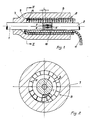
- two cable lengths 1, 2 of which it is wished to realize their connection are arranged coaxially face to face, with relative conductor stripped end portions 3, 4, namely locally devoid of the insulation surrounding the same, in order to carry out their electric connection.
- connection area there is arranged a sleeve 7, supported by a tubular body 8, in condition of high expansion, i.e. such as to bring the sleeve to an inner diameter sufficient for being slidingly fitted on one of the cable lengths to be connected, before the joining operation, to be then led onto the connection itself and tightened.
- the sleeve 7 can elastically contract, tightening on the insulating covering 5 of the conductors.
- the sleeve itself is realized with elastic characteristics and diameter, when in rest position, that permit its tightening on the insulation of the smallest cable of the group of cables for which it is foreseen and is expanded, on the tubular body 8, as far as a diameter that permits its insertion on the greatest of the cables of the group itself; this corresponds to expansion values comprised between 200 and 300% and is associated to a relative radial stress on the tubular body 8, corresponding to pressures up to 1MPa or higher.
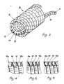
- the tubular body 8 is constituted by a plurality of coils 9 formed by a tape 10 of plastic material or the like, wound as a helix, the coils 9 being adjacent to each other and bound in a separable manner.
- the bond among the coils can be carried out by means of known techniques, as spot welding, glueing, mutual engagement of complementary profiles and so on, suitable to permit the tearing of the bond itself through a manual pull effected on one end 11, inserted through the free space left for it between the tubular body 8 and the outer surface of the insulation of the cables 1 and 2.
- the tubular body unwinds in the shape of a tape and moves aways from the inside of the sleeve which can therefore elastically tighten on the cables as wished.
- the tubular body 8 has a sufficiently great wall thickness S to prevent its collapse in consequence of the outer pressure; however, the corresponding thickness could bring the tape 10, if at constant section, to a very high bending stiffness that would impede the easy unwinding into rectilinear or substantially rectilinear shape, in the space available between the residual body 8, not yet unwound, and the cables 1 and 2 connected together.
- the tape 10 whose turns form, as said, the tubular body 8, is provided, as better shown in the figures 2 and 3, with the transversal notches 12 which make it possible that the section of tape resistant to bending, in the direction tending to open the notches 12, is considerably smaller than the section of the entire tape, which instead reacts wholly to the outer pressure, giving to the tape itself the wished degree of flexibility without impairing its resistance.
- the notches 12 are made on the lateral face of the tape, destined to come into contact with the opposite face of the successive coil in wound configuration and looking the opposite extremity with respect to the extremity of the tubular body from which the tape end 11 comes out.
- the tape 10 bends, for inserting in the part of tubular body not yet unwound, maintaining the side provided with notches outside the formed curve, so that said notches can open, making easy the bending of the tape itself.
- the bending of the tape in said direction is borne, at the notches, only by the tape portion 13 lying behind in the direction of the bending itself, which has a moment of inertia, for the bending in said plane, considerably lower than that in the opposite plane, the value of said moment of inertia can be chosen according to the need varying the depth of the notches 12.
- the tape can be easily bent in a plane substantially tangent to the surface of the cables 1, 2 and then be inserted in the space between them and the tubular body without suffering considerable torsions, and requiring consequently a free space between the cables and the tubular body slightly greater than the thickness 5 of the tape.
- the depth of the notches 12, which is convenient to be high for ensuring a high flexibility, has as limitation a value that leaves a section in the zone 13 large enough to withstand the tensile stresses required by the unwinding of the tape.
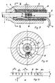
- the sides 10a and lob of the tape apt to go into mutual contact in winding position can be oblique, as illustrated in figure 4, which shows a portion of tubular body, sectioned at the notches of the tape 10 forming this latter, so that the portion 14 comprised between two notches leans against the side equally inclined of the portion 13 lying behind the notches, which withstands the bending.
- the sides 10a, 10b of the tape can be shaped in such a way as to form corresponding steps, or also, as shown in figure 6, it is possible to provide a symmetrical shaping of the sides 10a, 10b, for instance in the form of a V, so that the portion 14 comprised between two successive notches is guided bilaterally by the portion 13 lying behind the notches, ensuring thus the complete continuity of the outer surface of the tubular body and avoiding that unevenesses of the same originate printings more or less permanent on the inner surface of the sleeve 7.
- the faces of the notches 12 are made to be in contact to one another when the tape is in rectilinear configuration or is helically wound, therefore in the wound configuration the tape acts as a body devoid of discontinuities, both in the continuous zone 13 and in the zone provided with notches.
- the outer pressure produced by the expanded sleeve 7 corresponds to a compression stress in the whole section of the wall of the tubular body 8 and therefore the presence of the notches is not influential for the resistance.
- the assembly according to the invention comprising the tubular support and the sleeve fitted thereto, can be put on the market already prepared, i.e. with the tape partially unwound at one extremity of the tubular support and inserted into this latter, as far as to come out of the opposite part with its end, through which the pull for unwinding the turns of the support is exerted as previously illustrated.
- an alternative embodiment of the invention suggests, as shown in figures 7 and 8, to provide the tape 10 with notches 12′ and 12 ⁇ alternating on one and on the other of the lateral surfaces of the turns formed by said tape.
- the user can indifferently begin to unwind the end 11a or 11b of the tape for a certain portion, proceeding consequently to insert the unwound part into the residual tubular support to pull it out at the opposite extremity; for instance it is possible to unwind the end 11a and to insert it into the tubular support according to the arrow F1, as shown with dashed line, and to pull it out at the opposite extremity of the tubular support, by means of a pulling action according to the arrow F2.
- the notches 12 of the tape 10 can be made on the side of the tape intended to constitute, after the winding, the inner surface of the tubular body 8 formed by said tape.
- said notches can have the faces 12a, 12b forming a dihedron when the tape is arranged in rectilinear configuration, which come then into contact each other when the tape is helically bent, with the notches looking inwardly to form the coils 9, that are further tightened one against the other in consequence of the outer pressure applied by the sleeve 7.
- the behaviour of the so formed tubular body 8, under the effect of the outer pressure is substantially equivalent to that given by a body devoid of the notches 12; viceversa, in presence of a pull along the tape 10 intending to bring it to the rectilinear configuration, undoing the tubular body, the faces 12a, 12b of the notches move away from each other and the flexural resistance and the torsional resistance of the tape are supplied only by the thickness t of the section 13 of the tape itself lying below the notch, permitting thus to obtain a very great deformability, answering the requirements.
- the opening angle a of the notches 12 when the tape is in rectilinear position must be such as to give an opening value d of each notch equal to: where S is the thickness of the tape, and consequently of the wall of the tubular body 8, and n is the number of notches present in one coil so as to guarantee a tightly closed contact between the faces 12a, 12b and a bending as much as possible continuous to the tape when it is wound to form the tubular body 8.
- the tape 10 suffers, particularly near the zone of its separation from the body 8, a torsion that causes it to arrange in transversal direction in said space, as schematically shown in the figures 9 and 10; therefore in this case it is necessary to provide a free space between the body 8 and the greater one of the cables for which the sleeve is realized, that permits said torsion, said space being equal or greater than the diagonal of the tape section.
- the pitch p between two consecutive notches, or between two consecutive notches made on the same surface has to be such as to form at least eight notches for each coil but preferably a higher number of notches; in a preferred embodiment the pitch p is comprised between 0,5 and 2 times the thickness S.
- the width L of the tape i.e. the pitch of one coil is chosen not higher than 3 times the thickness of the tape and is comprised, preferably, between 0.5 and 1.5 times the thickness S.
- the greater values of said width can be used for tapes having notches according to the embodiments of figure 1 or 7, while with notches according to figure 9, since torsions can occur during the unwinding, it is preferred that the width values are lower.
- the indicated pressure value for example can correspond to a sleeve of the type described in the Italian patent application No. 19102 A/89, already cited, with inner diameter, in rest position, equal to 17 mm and wall thickness, in the same conditions, of 15 mm, expanded up to an inner diameter of 51 mm, i.e. of 200X.
- this second case can be relating to a sleeve of the same type as that described in the previous case, with inner diameter in rest position of 17 mm and thickness of 15 mm, expanded up to an inner diameter of 68 mm, i.e. of 300%.
- notches in both the directions described above, i.e. both on the inner surface and on the flank of each turn, or also notches engraving the tape in the plane transversal to its greater direction, with oblique direction with respect to its faces, or also in an oblique plane with respect to the longitudinal extension of the tape.
Landscapes
- Insulating Bodies (AREA)
- Cable Accessories (AREA)
Applications Claiming Priority (2)
| Application Number | Priority Date | Filing Date | Title |
|---|---|---|---|
| IT2062089 | 1989-05-24 | ||
| IT8920620A IT1229366B (it) | 1989-05-24 | 1989-05-24 | Complesso costituito da un manicotto, calzato su un supporto tubolare, particolarmente per giunti e terminali di cavi elettrici. |
Publications (2)
| Publication Number | Publication Date |
|---|---|
| EP0399263A2 true EP0399263A2 (fr) | 1990-11-28 |
| EP0399263A3 EP0399263A3 (fr) | 1991-07-03 |
Family
ID=11169662
Family Applications (1)
| Application Number | Title | Priority Date | Filing Date |
|---|---|---|---|
| EP19900108432 Withdrawn EP0399263A3 (fr) | 1989-05-24 | 1990-05-04 | Assemblage constitué par un manchon, monté sur un support tubulaire, en particulier pour jonctions et extrémités étanchéifiées de câbles électriques |
Country Status (4)
| Country | Link |
|---|---|
| US (1) | US5087492A (fr) |
| EP (1) | EP0399263A3 (fr) |
| CA (1) | CA2016862A1 (fr) |
| IT (1) | IT1229366B (fr) |
Cited By (13)
| Publication number | Priority date | Publication date | Assignee | Title |
|---|---|---|---|---|
| EP0547667A1 (fr) * | 1991-12-16 | 1993-06-23 | PIRELLI CAVI S.p.A. | Support tubulaire d'un manchon de recouvrement de jonction, en particulier de câbles électriques, et procédé et appareil pour la fabrication de ce support tubulaire |
| WO2006102330A1 (fr) * | 2005-03-24 | 2006-09-28 | Tyco Electronics Corporation | Dispositif de retenue, ensemble de revetement et procedes les integrant |
| EP1835591A1 (fr) * | 2006-03-16 | 2007-09-19 | Tyco Electronics Raychem GmbH | Support hélicoïdal et procédé de fabrication correspondant |
| EP1852949A1 (fr) | 2006-05-05 | 2007-11-07 | 3M Innovative Properties Company | Borne tubulaire pour câble |
| WO2007130811A2 (fr) | 2006-05-05 | 2007-11-15 | 3M Innovative Properties Company | Borne tubulaire d'un câble |
| EP1860749A2 (fr) | 2006-05-24 | 2007-11-28 | Tyco Electronics Raychem GmbH | Support de ruban hélicoïdal comportant un verrouillage mécanique et son procédé de fabrication |
| DE102008023963A1 (de) | 2008-05-16 | 2009-12-10 | Tyco Electronics Raychem Gmbh | Laserstrahl absorbierende Stützwendel sowie Verfahren und Vorrichtung zur Herstellung derselben |
| DE102007018915B4 (de) * | 2006-05-24 | 2009-12-24 | Tyco Electronics Raychem Gmbh | Stützwendel mit mechanischer Verriegelung und Verfahren zu deren Herstellung |
| EP2608338A1 (fr) | 2011-12-21 | 2013-06-26 | 3M Innovative Properties Company | Dispositif de raccordement de terminal pour câble d'alimentation |
| US9224522B2 (en) | 2013-02-04 | 2015-12-29 | Tyco Electronics Corporation | Holdout devices and cover assemblies and methods incorporating the same |
| US9224519B2 (en) | 2012-12-13 | 2015-12-29 | Tyco Electronics Corporation | Holdout devices and cover assemblies and methods incorporating the same |
| US9742180B2 (en) | 2013-06-26 | 2017-08-22 | 3M Innovative Properties Company | Power cable terminal connection device |
| US10594128B2 (en) | 2015-11-10 | 2020-03-17 | Te Connectivity Corporation | Holdout devices and cover assemblies and methods incorporating the same |
Families Citing this family (25)
| Publication number | Priority date | Publication date | Assignee | Title |
|---|---|---|---|---|
| IT1251986B (it) * | 1991-11-08 | 1995-05-27 | Pirelli Cavi Spa | Complesso di rivestimento di elementi cilindrici allungati giunti di cavi elettrici |
| IT1252219B (it) * | 1991-12-16 | 1995-06-05 | Pirelli Cavi Spa | Complesso di rivestimento di elementi cilindrici allungati quali giunti di cavi elettrici. |
| US6265065B1 (en) * | 1993-10-29 | 2001-07-24 | Mccallion James P. | Concrete reinforcement protection system |
| EP0767523A3 (fr) * | 1995-10-02 | 1997-07-23 | Minnesota Mining & Mfg | Dispositif de recouvrement amélioré |
| IT1275976B1 (it) * | 1995-03-27 | 1997-10-24 | Pirelli Cavi S P A Ora Pirelli | Supporto per un manicotto elastico |
| US5731051A (en) * | 1995-09-26 | 1998-03-24 | Minnesota Mining And Manufacturing Company | Fiber optic fusion splice protection sleeve |
| US5922423A (en) * | 1996-05-03 | 1999-07-13 | Jeremko; Daniel L. | One-piece removable core to support a hollow elastic member in a stretched state |
| US5741015A (en) * | 1996-06-17 | 1998-04-21 | Skinner; William O. | Pipe to manhole seal |
| US6393683B1 (en) | 1999-06-29 | 2002-05-28 | The Boeing Company | Masking application apparatus and method for application of a mask |
| US6485199B1 (en) | 2000-04-13 | 2002-11-26 | Amherst Holding Co. | Disposable optical fiber splice sleeve and method for applying same |
| US6444913B1 (en) * | 2001-10-15 | 2002-09-03 | Sui Chan Kao | Terminal connector stretcher for high-tension cable |
| EP1697599A2 (fr) * | 2003-10-30 | 2006-09-06 | Erico International Corporation | Raccord pour barres de renforcement |
| IL174621A (en) * | 2006-03-29 | 2010-06-30 | Krausz Metal Ind Ltd | Flexible adjustable seal strip |
| TW200810265A (en) * | 2006-05-31 | 2008-02-16 | Roxtec Ab | A plug unit for a cable entry |
| US7694978B2 (en) * | 2006-08-08 | 2010-04-13 | Federal-Mogul World Wide, Inc. | Gasket assembly and method of manufacture thereof |
| FR2926410B1 (fr) * | 2008-01-16 | 2010-02-19 | D App Et De Materiel Electr S | Ensemble pour recouvrir a enserrement un element allonge avec un manchon elastique de protection |
| KR101708072B1 (ko) | 2009-02-05 | 2017-02-17 | 쓰리엠 이노베이티브 프로퍼티즈 컴파니 | 실드 삭을 갖는 스플라이스 조립체 |
| US8853563B2 (en) | 2010-04-16 | 2014-10-07 | Thomas & Betts International, Llc | Cold shrink assembly |
| US9202612B2 (en) | 2012-09-28 | 2015-12-01 | Thomas & Betts International, Llc | Cold shrink assembly |
| US10021958B2 (en) * | 2013-01-14 | 2018-07-17 | Tenacious Holdings, Inc. | Tool safety strap |
| JP6115496B2 (ja) * | 2014-02-27 | 2017-04-19 | 住友電装株式会社 | 螺旋状支管及び螺旋状支管付グロメット |
| EP3001523B1 (fr) * | 2014-09-24 | 2018-11-14 | Tyco Electronics Raychem GmbH | Connecteur électrique pour connexion de bout en bout |
| CA3037450C (fr) * | 2016-09-19 | 2022-05-10 | Prysmian S.P.A. | Jonction pour cables a courant continu a haute tension |
| CN109167328B (zh) * | 2018-11-14 | 2020-12-29 | 淄博久安电气科技有限公司 | 一种内衬管 |
| CN110610786B (zh) * | 2019-09-17 | 2020-11-27 | 汇铂斯电子技术(苏州)有限公司 | 一种高阻燃性轨道交通专用线束生产工艺 |
Citations (3)
| Publication number | Priority date | Publication date | Assignee | Title |
|---|---|---|---|---|
| US3515798A (en) * | 1968-12-06 | 1970-06-02 | Minnesota Mining & Mfg | Elastic cover and removable cone assembly |
| WO1983000779A1 (fr) * | 1981-08-17 | 1983-03-03 | Minnesota Mining & Mfg | Couverture elastique pour des couplages sous pression |
| US4389440A (en) * | 1982-02-08 | 1983-06-21 | Minnesota Mining & Manufacturing Company | Torque preloaded elastic cover for torque coupling |
Family Cites Families (2)
| Publication number | Priority date | Publication date | Assignee | Title |
|---|---|---|---|---|
| JPS59121172U (ja) * | 1983-02-04 | 1984-08-15 | ミネソタ・マイニング・アンド・マニユフアクチユアリング・コンパニ− | ケーブル電線被覆の剥離部分のカバー装置 |
| US4671028A (en) * | 1984-08-07 | 1987-06-09 | Figone Frank M | Intrinsically hinged load member |
-
1989
- 1989-05-24 IT IT8920620A patent/IT1229366B/it active
-
1990
- 1990-05-04 EP EP19900108432 patent/EP0399263A3/fr not_active Withdrawn
- 1990-05-15 CA CA002016862A patent/CA2016862A1/fr not_active Abandoned
- 1990-05-23 US US07/527,517 patent/US5087492A/en not_active Expired - Fee Related
Patent Citations (3)
| Publication number | Priority date | Publication date | Assignee | Title |
|---|---|---|---|---|
| US3515798A (en) * | 1968-12-06 | 1970-06-02 | Minnesota Mining & Mfg | Elastic cover and removable cone assembly |
| WO1983000779A1 (fr) * | 1981-08-17 | 1983-03-03 | Minnesota Mining & Mfg | Couverture elastique pour des couplages sous pression |
| US4389440A (en) * | 1982-02-08 | 1983-06-21 | Minnesota Mining & Manufacturing Company | Torque preloaded elastic cover for torque coupling |
Cited By (24)
| Publication number | Priority date | Publication date | Assignee | Title |
|---|---|---|---|---|
| EP0547667A1 (fr) * | 1991-12-16 | 1993-06-23 | PIRELLI CAVI S.p.A. | Support tubulaire d'un manchon de recouvrement de jonction, en particulier de câbles électriques, et procédé et appareil pour la fabrication de ce support tubulaire |
| US5560969A (en) * | 1991-12-16 | 1996-10-01 | Pirelli Cavi S.P.A. | Tubular supporting element for a sleeve for covering junctions, particularly of cables for transmitting electrical energy |
| US5589123A (en) * | 1991-12-16 | 1996-12-31 | Pirelli Cavi S.P.A. | Process of making a tubular supporting element |
| WO2006102330A1 (fr) * | 2005-03-24 | 2006-09-28 | Tyco Electronics Corporation | Dispositif de retenue, ensemble de revetement et procedes les integrant |
| US7265293B2 (en) | 2005-03-24 | 2007-09-04 | Tyco Electronics Corporation | Holdout devices and cover assemblies and methods incorporating the same |
| EP1835591A1 (fr) * | 2006-03-16 | 2007-09-19 | Tyco Electronics Raychem GmbH | Support hélicoïdal et procédé de fabrication correspondant |
| DE102006012593A1 (de) * | 2006-03-16 | 2007-09-20 | Tyco Electronics Raychem Gmbh | Stützwendel und Verfahren zu dessen Herstellung |
| EP1852949A1 (fr) | 2006-05-05 | 2007-11-07 | 3M Innovative Properties Company | Borne tubulaire pour câble |
| WO2007130811A2 (fr) | 2006-05-05 | 2007-11-15 | 3M Innovative Properties Company | Borne tubulaire d'un câble |
| US7744977B2 (en) | 2006-05-24 | 2010-06-29 | Tyco Electronics Raychem Gmbh | Support coil comprising a mechanical locking means and method for the production thereof |
| DE102007018915B4 (de) * | 2006-05-24 | 2009-12-24 | Tyco Electronics Raychem Gmbh | Stützwendel mit mechanischer Verriegelung und Verfahren zu deren Herstellung |
| EP1860749A2 (fr) | 2006-05-24 | 2007-11-28 | Tyco Electronics Raychem GmbH | Support de ruban hélicoïdal comportant un verrouillage mécanique et son procédé de fabrication |
| US9099857B2 (en) | 2008-05-16 | 2015-08-04 | Tyco Electronics Raychem Gmbh | Laser-beam-absorbing helical support and process and device for the production thereof |
| DE102008023963A1 (de) | 2008-05-16 | 2009-12-10 | Tyco Electronics Raychem Gmbh | Laserstrahl absorbierende Stützwendel sowie Verfahren und Vorrichtung zur Herstellung derselben |
| EP2608338A1 (fr) | 2011-12-21 | 2013-06-26 | 3M Innovative Properties Company | Dispositif de raccordement de terminal pour câble d'alimentation |
| EP2698891A1 (fr) | 2011-12-21 | 2014-02-19 | 3M Innovative Properties Company | Dispositif de connexion de borne pour un câble électrique |
| WO2013096354A1 (fr) | 2011-12-21 | 2013-06-27 | 3M Innovative Properties Company | Dispositif de connexion de borne pour câble d'alimentation électrique |
| US9429594B2 (en) | 2011-12-21 | 2016-08-30 | 3M Innovative Properties Company | Terminal connection device for a power cable |
| US9960530B2 (en) | 2011-12-21 | 2018-05-01 | 3M Innovative Properties Company | Terminal connection device for a power cable |
| US9224519B2 (en) | 2012-12-13 | 2015-12-29 | Tyco Electronics Corporation | Holdout devices and cover assemblies and methods incorporating the same |
| US9224522B2 (en) | 2013-02-04 | 2015-12-29 | Tyco Electronics Corporation | Holdout devices and cover assemblies and methods incorporating the same |
| US9627101B2 (en) | 2013-02-04 | 2017-04-18 | Te Connectivity Corporation | Methods for covering an elongate substrate |
| US9742180B2 (en) | 2013-06-26 | 2017-08-22 | 3M Innovative Properties Company | Power cable terminal connection device |
| US10594128B2 (en) | 2015-11-10 | 2020-03-17 | Te Connectivity Corporation | Holdout devices and cover assemblies and methods incorporating the same |
Also Published As
| Publication number | Publication date |
|---|---|
| CA2016862A1 (fr) | 1990-11-24 |
| IT8920620A0 (it) | 1989-05-24 |
| EP0399263A3 (fr) | 1991-07-03 |
| IT1229366B (it) | 1991-08-08 |
| US5087492A (en) | 1992-02-11 |
Similar Documents
| Publication | Publication Date | Title |
|---|---|---|
| EP0399263A2 (fr) | Assemblage constitué par un manchon, monté sur un support tubulaire, en particulier pour jonctions et extrémités étanchéifiées de câbles électriques | |
| US5670223A (en) | Support core ribbon for cold-shrink tube | |
| EP0547656B1 (fr) | Ensemble de recouvrement d'objets cylindriques oblongés tels que des jonctions de câbles électriques | |
| CA1174310A (fr) | Manchons pour cables | |
| US5473723A (en) | Optical fibre sheathing tube | |
| WO1999008355A1 (fr) | Ame lamifiee pour tube retrecissable a froid | |
| AU668521B2 (en) | Enclosure assembly for use over elongate cylindrical objects such as electric cable splices | |
| US5878465A (en) | Flexible cladding | |
| EP0169276B1 (fr) | Procédé pour envelopper des câbles avec des gaines pour la protection contre la corrosion et/ou pour des raisons esthétiques | |
| GB2316461A (en) | Bending restrictor | |
| EP0074280A2 (fr) | Elément de fermeture rétrécissable | |
| US4140412A (en) | Method of covering a joint of two rope ends | |
| SK280421B6 (sk) | Ťažná hlavica na optický kábel | |
| EP0490941A1 (fr) | Joint etanche. | |
| GB2057788A (en) | Tubular fittings for electric cables and pipelines and method for producing such fittings | |
| DK155393B (da) | Boejet klemme for elektrisk forbindelse | |
| WO2013096287A2 (fr) | Noyau de support pour tube rétrécissable à froid | |
| US4569708A (en) | Method for covering cables with sheaths for corrosion protection and/or aesthetics | |
| AU641619B2 (en) | Conduit liner assembly and method for installation | |
| JPH0260005A (ja) | 光学的な通信伝送線を有する架空導体 | |
| JP2789091B2 (ja) | 光フアイバケーブル分岐部構造体 | |
| EP0778929A1 (fr) | Raccord de tubes, arme a calibres variables | |
| US20090269529A1 (en) | Support Coil With Mechanical Locking Device and Method For Its Manufacture | |
| JPH0318407B2 (fr) | ||
| EP0450271A2 (fr) | Procédé de jonctionnement d'armure |
Legal Events
| Date | Code | Title | Description |
|---|---|---|---|
| PUAI | Public reference made under article 153(3) epc to a published international application that has entered the european phase |
Free format text: ORIGINAL CODE: 0009012 |
|
| AK | Designated contracting states |
Kind code of ref document: A2 Designated state(s): DE ES FR GB |
|
| PUAL | Search report despatched |
Free format text: ORIGINAL CODE: 0009013 |
|
| AK | Designated contracting states |
Kind code of ref document: A3 Designated state(s): DE ES FR GB |
|
| RAP1 | Party data changed (applicant data changed or rights of an application transferred) |
Owner name: PIRELLI CAVI S.P.A. |
|
| 17P | Request for examination filed |
Effective date: 19911223 |
|
| STAA | Information on the status of an ep patent application or granted ep patent |
Free format text: STATUS: THE APPLICATION HAS BEEN WITHDRAWN |
|
| 18W | Application withdrawn |
Withdrawal date: 19921215 |
|
| R18W | Application withdrawn (corrected) |
Effective date: 19921209 |