US6444913B1 - Terminal connector stretcher for high-tension cable - Google Patents
Terminal connector stretcher for high-tension cable Download PDFInfo
- Publication number
- US6444913B1 US6444913B1 US09/975,971 US97597101A US6444913B1 US 6444913 B1 US6444913 B1 US 6444913B1 US 97597101 A US97597101 A US 97597101A US 6444913 B1 US6444913 B1 US 6444913B1
- Authority
- US
- United States
- Prior art keywords
- terminal connector
- cable terminal
- pawl ring
- stretcher
- tension cable
- Prior art date
- Legal status (The legal status is an assumption and is not a legal conclusion. Google has not performed a legal analysis and makes no representation as to the accuracy of the status listed.)
- Expired - Fee Related
Links
Images


Classifications
-
- H—ELECTRICITY
- H02—GENERATION; CONVERSION OR DISTRIBUTION OF ELECTRIC POWER
- H02G—INSTALLATION OF ELECTRIC CABLES OR LINES, OR OF COMBINED OPTICAL AND ELECTRIC CABLES OR LINES
- H02G15/00—Cable fittings
- H02G15/08—Cable junctions
- H02G15/18—Cable junctions protected by sleeves, e.g. for communication cable
- H02G15/182—Cable junctions protected by sleeves, e.g. for communication cable held in expanded condition in radial direction prior to installation
- H02G15/1826—Cable junctions protected by sleeves, e.g. for communication cable held in expanded condition in radial direction prior to installation on a removable hollow core, e.g. a tube
-
- H—ELECTRICITY
- H02—GENERATION; CONVERSION OR DISTRIBUTION OF ELECTRIC POWER
- H02G—INSTALLATION OF ELECTRIC CABLES OR LINES, OR OF COMBINED OPTICAL AND ELECTRIC CABLES OR LINES
- H02G1/00—Methods or apparatus specially adapted for installing, maintaining, repairing or dismantling electric cables or lines
- H02G1/14—Methods or apparatus specially adapted for installing, maintaining, repairing or dismantling electric cables or lines for joining or terminating cables
-
- Y—GENERAL TAGGING OF NEW TECHNOLOGICAL DEVELOPMENTS; GENERAL TAGGING OF CROSS-SECTIONAL TECHNOLOGIES SPANNING OVER SEVERAL SECTIONS OF THE IPC; TECHNICAL SUBJECTS COVERED BY FORMER USPC CROSS-REFERENCE ART COLLECTIONS [XRACs] AND DIGESTS
- Y10—TECHNICAL SUBJECTS COVERED BY FORMER USPC
- Y10T—TECHNICAL SUBJECTS COVERED BY FORMER US CLASSIFICATION
- Y10T29/00—Metal working
- Y10T29/53—Means to assemble or disassemble
- Y10T29/53657—Means to assemble or disassemble to apply or remove a resilient article [e.g., tube, sleeve, etc.]
Definitions
- the present invention relates to high-tension cable terminal connectors and, more specifically, to a cable terminal connector stretcher for high-tension cable, which enables the cable terminal connector to be quickly installed with less labor consumption.
- a pre-mold/pre-fabricated type cable terminal connector as shown in FIG. 1A, is comprised of a plurality of electrically insulative disk nuts 10 fastened to on e another in series.
- the disk nuts 10 have a center r through hole 10 a fitting the outer diameter of the cable 100 .
- silicon lubricating grease is applied to the periphery of the cable 100 , and then the cable is forced into the center through hole 10 a of each disk nut 10 .
- a heatshrink type cable terminal connector 11 as shown in FIG. 1B has a center through hole 11 a of diameter greater than the outer diameter of the cable 100 . After insertion of the cable 100 through the center through hole 11 a of the heat-shrink cable terminal connector 11 , a torch is operated to bake the cable terminal connector 11 , causing it to shrink. However, the heatshrink cable terminal connector 11 tends to be burned out accidentally when baking. When a cold-shrink cable terminal connector 11 is used, as shown in FIG.
- a tool (not shown) is inserted t through the center through hole 11 a of the cold-shrink cable terminal connector 11 and operated to expand the outer diameter of the cold-shrink cable terminal connector 11 , and then a spiral tube 12 (see FIG. 2) is inserted into the tool in the center through hole 11 a of the cold-shrink cable terminal connector 11 , and then the tool is removed from the coldshrink cable terminal connector 11 , and then the cable 100 is inserted through the spiral tube 12 in the center through hole 11 a of the cold-shrink cable terminal connector 11 after having been coated with a layer of silicon lubricating grease, and then the spiral tube 12 is pulled out of the cold-shrink cable terminal connector 11 . After removal of the spiral tube 12 from the cold-shrink cable terminal connector 11 , the cold-shrink cable terminal connector 11 shrinks to hold down the cable 100 . This method is functional, however the use of the spiral tube 12 greatly increases the installation cost.
- the cable terminal connector stretcher comprises a pawl ring, the pawl ring comprising plurality of equiangularly spaced and longitudinally extended pawls, and locking loop adapted to be fastened to the pawls of the pawl ring to secure the pawl ring to a high-tension cable terminal connector.
- the locking loop is comprised of a strip of resilient material having two ends fastened together by a snap.
- FIG. 1A shows the installation of a pre-mold cable terminal connector according to the prior art.
- FIG. 1B shows the installation of a heat-shrink type cable terminal connector according to the prior art.
- FIG. 1C shows the installation of a cold-shrink type cable terminal connector according to the prior art.
- FIG. 2 shows a spiral tube of the prior art.
- FIG. 3A is an exploded view of a cable terminal connector stretcher according to the present invention.
- FIG. 3B is an assembled view of a cable terminal connector stretcher according to the present invention.
- FIG. 4 illustrates the assembly process of the locking loop for the cable terminal connector stretcher according to he present invention.
- FIG. 5A, FIG. 5B, and FIG. 5C show different pawl ring and locking loop fastening arrangements according to the present invention.
- FIG. 6 shows the application of the present invention (Step I).
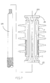
- FIG. 7 shows the application of the present invention (Step II).
- FIG. 8 shows the application of the present invention (Step III).
- FIG. 9 shows the application of the present invention (Step IV).
- a cable terminal connector stretcher 200 is shown comprised of a pawl ring 20 , and a locking loop 22 .
- the pawl ring 20 comprises a plurality of equiangularly spaced and longitudinally extended pawls 21 .
- the locking loop 22 is to be fastened to the pawls 21 to secure the pawl ring 20 to a high-tension cable terminal connector.
- the locking loop 22 is formed of a strip of resilient material that has its ends fastened together by, for example, a snap joint.
- the locking loop 22 can be fastened to the pawls 21 of the pawl ring 20 by any of a variety of known joints or coupling structures.
- a tool 30 is used and inserted into the high-tension cable terminal connector 11 to expand the longitudinal through hole 11 a of the high-tension cable terminal connector 11 (see FIG. 6 ), and then the pawls 21 of the pawl ring 20 are radially inwardly compressed and then inserted through the tool 30 in the longitudinal through hole 11 a of the high-tension cable terminal connector 11 and the locking loop 22 is fastened to the pawls 21 of the pawl ring 20 to stop the pawl ring 20 from escaping out of the high-tension cable terminal connector 11 and then the tool 30 is removed from the high-tension cable terminal connector 11 (see FIG.
- the high-tension cable 100 is peripherally coated with a layer of silicon lubricating grease and then inserted through the terminal connector stretcher 200 (see FIG. 8 ), and then the locking loop 22 is unfastened from the pawl ring 20 and the pawl ring 20 is then removed from the high-tension cable terminal connector 11 , enabling the high-tension cable terminal connector 11 to be secured to the periphery of the high-tension cable 100 .
Landscapes
- Details Of Connecting Devices For Male And Female Coupling (AREA)
Abstract
A cable terminal connector stretcher includes a pawl ring, the pawl ring having plurality of equiangularly spaced and longitudinally extended pawls, and locking loop adapted to be fastened to the pawls of the pawl ring to secure the pawl ring to a high-tension cable terminal connector.
Description
The present invention relates to high-tension cable terminal connectors and, more specifically, to a cable terminal connector stretcher for high-tension cable, which enables the cable terminal connector to be quickly installed with less labor consumption.
Conventional high-tension cable terminal connectors include pre-mold/pre-fabricated type, heat-shrink type, and cold-shrink type. A pre-mold/pre-fabricated type cable terminal connector, as shown in FIG. 1A, is comprised of a plurality of electrically insulative disk nuts 10 fastened to on e another in series. The disk nuts 10 have a center r through hole 10 a fitting the outer diameter of the cable 100. During installation, silicon lubricating grease is applied to the periphery of the cable 100, and then the cable is forced into the center through hole 10 a of each disk nut 10. Because the disk nuts 10 are injection-molded from plastics, it is difficult to control the shrinkage of the center through hole 10 a, and rainwater tends to leak in the gap between the cable 100 and the disk nuts 10, causing a short-circuit. A heatshrink type cable terminal connector 11 as shown in FIG. 1B, has a center through hole 11 a of diameter greater than the outer diameter of the cable 100. After insertion of the cable 100 through the center through hole 11 a of the heat-shrink cable terminal connector 11, a torch is operated to bake the cable terminal connector 11, causing it to shrink. However, the heatshrink cable terminal connector 11 tends to be burned out accidentally when baking. When a cold-shrink cable terminal connector 11 is used, as shown in FIG. 1C, a tool (not shown) is inserted t through the center through hole 11 a of the cold-shrink cable terminal connector 11 and operated to expand the outer diameter of the cold-shrink cable terminal connector 11, and then a spiral tube 12 (see FIG. 2) is inserted into the tool in the center through hole 11 a of the cold-shrink cable terminal connector 11, and then the tool is removed from the coldshrink cable terminal connector 11, and then the cable 100 is inserted through the spiral tube 12 in the center through hole 11 a of the cold-shrink cable terminal connector 11 after having been coated with a layer of silicon lubricating grease, and then the spiral tube 12 is pulled out of the cold-shrink cable terminal connector 11. After removal of the spiral tube 12 from the cold-shrink cable terminal connector 11, the cold-shrink cable terminal connector 11 shrinks to hold down the cable 100. This method is functional, however the use of the spiral tube 12 greatly increases the installation cost.
It is the main object of the present invention to provide a cable terminal connector stretcher for high-tension cable, which saves much cable terminal connector installation cost and labor. According to the present invention, the cable terminal connector stretcher comprises a pawl ring, the pawl ring comprising plurality of equiangularly spaced and longitudinally extended pawls, and locking loop adapted to be fastened to the pawls of the pawl ring to secure the pawl ring to a high-tension cable terminal connector. According to another aspect of the present invention, the locking loop is comprised of a strip of resilient material having two ends fastened together by a snap.
FIG. 1A shows the installation of a pre-mold cable terminal connector according to the prior art.
FIG. 1B shows the installation of a heat-shrink type cable terminal connector according to the prior art.
FIG. 1C shows the installation of a cold-shrink type cable terminal connector according to the prior art.
FIG. 2 shows a spiral tube of the prior art.
FIG. 3A is an exploded view of a cable terminal connector stretcher according to the present invention.
FIG. 3B is an assembled view of a cable terminal connector stretcher according to the present invention.
FIG. 4 illustrates the assembly process of the locking loop for the cable terminal connector stretcher according to he present invention.
FIG. 5A, FIG. 5B, and FIG. 5C show different pawl ring and locking loop fastening arrangements according to the present invention.
FIG. 6 shows the application of the present invention (Step I).
FIG. 7 shows the application of the present invention (Step II).
FIG. 8 shows the application of the present invention (Step III).
FIG. 9 shows the application of the present invention (Step IV).
Referring to FIGS. 3A and 3B, a cable terminal connector stretcher 200 is shown comprised of a pawl ring 20, and a locking loop 22. the pawl ring 20 comprises a plurality of equiangularly spaced and longitudinally extended pawls 21. The locking loop 22 is to be fastened to the pawls 21 to secure the pawl ring 20 to a high-tension cable terminal connector.
Referring to FIG. 4, the locking loop 22 is formed of a strip of resilient material that has its ends fastened together by, for example, a snap joint.
Referring to FIGS. 5A, 5B and 5C, the locking loop 22 can be fastened to the pawls 21 of the pawl ring 20 by any of a variety of known joints or coupling structures.
Referring to FIGS. From 6 through 9, a tool 30 is used and inserted into the high-tension cable terminal connector 11 to expand the longitudinal through hole 11 a of the high-tension cable terminal connector 11 (see FIG. 6), and then the pawls 21 of the pawl ring 20 are radially inwardly compressed and then inserted through the tool 30 in the longitudinal through hole 11 a of the high-tension cable terminal connector 11 and the locking loop 22 is fastened to the pawls 21 of the pawl ring 20 to stop the pawl ring 20 from escaping out of the high-tension cable terminal connector 11 and then the tool 30 is removed from the high-tension cable terminal connector 11 (see FIG. 7), and then the high-tension cable 100 is peripherally coated with a layer of silicon lubricating grease and then inserted through the terminal connector stretcher 200 (see FIG. 8), and then the locking loop 22 is unfastened from the pawl ring 20 and the pawl ring 20 is then removed from the high-tension cable terminal connector 11, enabling the high-tension cable terminal connector 11 to be secured to the periphery of the high-tension cable 100.
Claims (2)
1. A cable terminal connector stretcher comprising a pawl ring, said pawl ring comprising a plurality of equiangularly spaced and longitudinally extended pawls, and a locking loop fastenable to said pawls of said pawl ring to secure said pawl ring to a high tension cable terminal connector.
2. The cable terminal connector stretcher of claim 1 wherein said locking loop is comprised of a strip of resilient material having two ends fastened together by a snap.
Priority Applications (1)
| Application Number | Priority Date | Filing Date | Title |
|---|---|---|---|
| US09/975,971 US6444913B1 (en) | 2001-10-15 | 2001-10-15 | Terminal connector stretcher for high-tension cable |
Applications Claiming Priority (1)
| Application Number | Priority Date | Filing Date | Title |
|---|---|---|---|
| US09/975,971 US6444913B1 (en) | 2001-10-15 | 2001-10-15 | Terminal connector stretcher for high-tension cable |
Publications (1)
| Publication Number | Publication Date |
|---|---|
| US6444913B1 true US6444913B1 (en) | 2002-09-03 |
Family
ID=25523592
Family Applications (1)
| Application Number | Title | Priority Date | Filing Date |
|---|---|---|---|
| US09/975,971 Expired - Fee Related US6444913B1 (en) | 2001-10-15 | 2001-10-15 | Terminal connector stretcher for high-tension cable |
Country Status (1)
| Country | Link |
|---|---|
| US (1) | US6444913B1 (en) |
Cited By (14)
| Publication number | Priority date | Publication date | Assignee | Title |
|---|---|---|---|---|
| US20040177485A1 (en) * | 2001-08-29 | 2004-09-16 | Yaron Lihod | Boot-slider |
| US20060213678A1 (en) * | 2005-03-24 | 2006-09-28 | Kamel Sherif I | Holdout devices and cover assemblies and methods incorporating the same |
| US20070149850A1 (en) * | 2005-12-22 | 2007-06-28 | Spivey James T | Endoscope endcap attachment tool |
| US20070225728A1 (en) * | 2006-03-22 | 2007-09-27 | Ethicon Endo-Surgery, Inc. | Intubation system for use with an endoscope |
| US20070225694A1 (en) * | 2006-03-22 | 2007-09-27 | Ethicon Endo-Surgery, Inc. | Intubation device for enteral feeding |
| US20080308284A1 (en) * | 2007-06-15 | 2008-12-18 | Baker Hughes Incorporated | Elastomeric element installation tool and method |
| US20090068858A1 (en) * | 2007-08-17 | 2009-03-12 | Centipede Systems, Inc. | Miniature electrical ball and tube socket assembly with self-capturing multiple-contact-point coupling |
| US20090282669A1 (en) * | 2008-05-13 | 2009-11-19 | Randolf Von Oepen | Method And Apparatus For Reducing Stress During Stent Manufacture |
| US20100273364A1 (en) * | 2009-04-22 | 2010-10-28 | Centipede Systems, Inc. | Axially Compliant Microelectronic Contactor |
| US9224519B2 (en) | 2012-12-13 | 2015-12-29 | Tyco Electronics Corporation | Holdout devices and cover assemblies and methods incorporating the same |
| US9224522B2 (en) | 2013-02-04 | 2015-12-29 | Tyco Electronics Corporation | Holdout devices and cover assemblies and methods incorporating the same |
| US20160036188A1 (en) * | 2013-01-31 | 2016-02-04 | Tyco Electronics Corporation | Tools and methods for installing cover sleeves on electrical connections |
| US20170033545A1 (en) * | 2015-07-28 | 2017-02-02 | Societe Industrielle De Construction D'appareils Et De Materiel Electriques | Assembly for tightly covering an elongate member with a protective elastic tubular body |
| US10594128B2 (en) | 2015-11-10 | 2020-03-17 | Te Connectivity Corporation | Holdout devices and cover assemblies and methods incorporating the same |
Citations (11)
| Publication number | Priority date | Publication date | Assignee | Title |
|---|---|---|---|---|
| US3808352A (en) * | 1972-10-26 | 1974-04-30 | Minnesota Mining & Mfg | Elastomeric terminal insulator and stress cone and conductor terminated therewith |
| US4389440A (en) * | 1982-02-08 | 1983-06-21 | Minnesota Mining & Manufacturing Company | Torque preloaded elastic cover for torque coupling |
| US4871599A (en) * | 1987-05-13 | 1989-10-03 | Minnesota Mining And Manufacturing Company | Support helix for a radially expanded resilient sleeve |
| US5087492A (en) * | 1989-05-24 | 1992-02-11 | Societa' Cavi Pirelli S.P.A. | Expanded elastic sleeve with wound internal support for electric cable joints and sealing ends |
| US5130495A (en) * | 1991-01-24 | 1992-07-14 | G & W Electric Company | Cable terminator |
| US5408047A (en) * | 1990-10-25 | 1995-04-18 | Minnesota Mining And Manufacturing Company | Transition joint for oil-filled cables |
| US5468911A (en) * | 1992-08-14 | 1995-11-21 | Framatome Connectors International | Screening hull for electrical cable |
| US5495650A (en) * | 1993-06-25 | 1996-03-05 | Euromold | Tubular support for installing a contractable elastic sleeve |
| US5685052A (en) * | 1996-04-11 | 1997-11-11 | The United States Of America As Represented By The Department Of Energy | Graphitic packing removal tool |
| US5944929A (en) * | 1995-03-27 | 1999-08-31 | Pirelli Cavi S.P.A. | Elastic sleeve support |
| US6049960A (en) * | 1995-03-23 | 2000-04-18 | Zittauer Kunststoff Gmbh | Method and device for sliding and positioning sleeve-shaped elastic components on cylindrical or conical base bodies |
-
2001
- 2001-10-15 US US09/975,971 patent/US6444913B1/en not_active Expired - Fee Related
Patent Citations (11)
| Publication number | Priority date | Publication date | Assignee | Title |
|---|---|---|---|---|
| US3808352A (en) * | 1972-10-26 | 1974-04-30 | Minnesota Mining & Mfg | Elastomeric terminal insulator and stress cone and conductor terminated therewith |
| US4389440A (en) * | 1982-02-08 | 1983-06-21 | Minnesota Mining & Manufacturing Company | Torque preloaded elastic cover for torque coupling |
| US4871599A (en) * | 1987-05-13 | 1989-10-03 | Minnesota Mining And Manufacturing Company | Support helix for a radially expanded resilient sleeve |
| US5087492A (en) * | 1989-05-24 | 1992-02-11 | Societa' Cavi Pirelli S.P.A. | Expanded elastic sleeve with wound internal support for electric cable joints and sealing ends |
| US5408047A (en) * | 1990-10-25 | 1995-04-18 | Minnesota Mining And Manufacturing Company | Transition joint for oil-filled cables |
| US5130495A (en) * | 1991-01-24 | 1992-07-14 | G & W Electric Company | Cable terminator |
| US5468911A (en) * | 1992-08-14 | 1995-11-21 | Framatome Connectors International | Screening hull for electrical cable |
| US5495650A (en) * | 1993-06-25 | 1996-03-05 | Euromold | Tubular support for installing a contractable elastic sleeve |
| US6049960A (en) * | 1995-03-23 | 2000-04-18 | Zittauer Kunststoff Gmbh | Method and device for sliding and positioning sleeve-shaped elastic components on cylindrical or conical base bodies |
| US5944929A (en) * | 1995-03-27 | 1999-08-31 | Pirelli Cavi S.P.A. | Elastic sleeve support |
| US5685052A (en) * | 1996-04-11 | 1997-11-11 | The United States Of America As Represented By The Department Of Energy | Graphitic packing removal tool |
Cited By (29)
| Publication number | Priority date | Publication date | Assignee | Title |
|---|---|---|---|---|
| US20040177485A1 (en) * | 2001-08-29 | 2004-09-16 | Yaron Lihod | Boot-slider |
| US20060213678A1 (en) * | 2005-03-24 | 2006-09-28 | Kamel Sherif I | Holdout devices and cover assemblies and methods incorporating the same |
| US7265293B2 (en) | 2005-03-24 | 2007-09-04 | Tyco Electronics Corporation | Holdout devices and cover assemblies and methods incorporating the same |
| US20070149850A1 (en) * | 2005-12-22 | 2007-06-28 | Spivey James T | Endoscope endcap attachment tool |
| US7771396B2 (en) | 2006-03-22 | 2010-08-10 | Ethicon Endo-Surgery, Inc. | Intubation device for enteral feeding |
| US20070225694A1 (en) * | 2006-03-22 | 2007-09-27 | Ethicon Endo-Surgery, Inc. | Intubation device for enteral feeding |
| US20070225728A1 (en) * | 2006-03-22 | 2007-09-27 | Ethicon Endo-Surgery, Inc. | Intubation system for use with an endoscope |
| US7803137B2 (en) | 2006-03-22 | 2010-09-28 | Ethicon Endo-Surgery, Inc. | Intubation system for use with an endoscope |
| US20080308284A1 (en) * | 2007-06-15 | 2008-12-18 | Baker Hughes Incorporated | Elastomeric element installation tool and method |
| US8365374B2 (en) * | 2007-06-15 | 2013-02-05 | Baker Hughes Incorporated | Elastomeric element installation tool and method |
| US20100105220A1 (en) * | 2007-08-17 | 2010-04-29 | Centipede Systems, Inc. | Miniature electrical ball and tube socket assembly with self-capturing multiple-contact-point coupling |
| US7674113B2 (en) | 2007-08-17 | 2010-03-09 | Centipede Systems, Inc. | Miniature electrical ball and tube socket assembly with self-capturing multiple-contact-point coupling |
| US20090305523A1 (en) * | 2007-08-17 | 2009-12-10 | Centipede Systems, Inc. | Miniature electrical ball and tube socket assembly with self-capturing multiple-contact-point coupling |
| US7837476B2 (en) | 2007-08-17 | 2010-11-23 | Centipede Systems, Inc. | Miniature electrical ball and tube socket assembly with self-capturing multiple-contact-point coupling |
| US20090068858A1 (en) * | 2007-08-17 | 2009-03-12 | Centipede Systems, Inc. | Miniature electrical ball and tube socket assembly with self-capturing multiple-contact-point coupling |
| US7980862B2 (en) | 2007-08-17 | 2011-07-19 | Centipede Systems, Inc. | Miniature electrical socket assembly with self-capturing multiple-contact-point coupling |
| US7985077B2 (en) | 2007-08-17 | 2011-07-26 | Centipede Systems, Inc. | Miniature electrical ball and tube socket assembly with self-capturing multiple-contact-point coupling |
| US8261420B2 (en) * | 2008-05-13 | 2012-09-11 | Abbott Laboratories | Method and apparatus for reducing stress during stent manufacture |
| US20090282669A1 (en) * | 2008-05-13 | 2009-11-19 | Randolf Von Oepen | Method And Apparatus For Reducing Stress During Stent Manufacture |
| US20100273364A1 (en) * | 2009-04-22 | 2010-10-28 | Centipede Systems, Inc. | Axially Compliant Microelectronic Contactor |
| US7955088B2 (en) * | 2009-04-22 | 2011-06-07 | Centipede Systems, Inc. | Axially compliant microelectronic contactor |
| US9224519B2 (en) | 2012-12-13 | 2015-12-29 | Tyco Electronics Corporation | Holdout devices and cover assemblies and methods incorporating the same |
| US20160036188A1 (en) * | 2013-01-31 | 2016-02-04 | Tyco Electronics Corporation | Tools and methods for installing cover sleeves on electrical connections |
| US9779857B2 (en) * | 2013-01-31 | 2017-10-03 | Te Connectivity Corporation | Tool for installing cover sleeves on electrical connectors |
| US9224522B2 (en) | 2013-02-04 | 2015-12-29 | Tyco Electronics Corporation | Holdout devices and cover assemblies and methods incorporating the same |
| US9627101B2 (en) | 2013-02-04 | 2017-04-18 | Te Connectivity Corporation | Methods for covering an elongate substrate |
| US20170033545A1 (en) * | 2015-07-28 | 2017-02-02 | Societe Industrielle De Construction D'appareils Et De Materiel Electriques | Assembly for tightly covering an elongate member with a protective elastic tubular body |
| US9972990B2 (en) * | 2015-07-28 | 2018-05-15 | Societe Industrielle De Construction D'appareils Et De Materiel Electriques | Assembly for tightly covering an elongate member with a protective elastic tubular body |
| US10594128B2 (en) | 2015-11-10 | 2020-03-17 | Te Connectivity Corporation | Holdout devices and cover assemblies and methods incorporating the same |
Similar Documents
| Publication | Publication Date | Title |
|---|---|---|
| US6444913B1 (en) | Terminal connector stretcher for high-tension cable | |
| US6994588B2 (en) | Compression connector for coaxial cable and method of installation | |
| US4046451A (en) | Connector for coaxial cable with annularly corrugated outer conductor | |
| US7182628B2 (en) | Cable connector having interchangeable color bands | |
| US8016613B2 (en) | Coaxial connector with locking sleeve for terminating cable | |
| US6352448B1 (en) | Cable TV end connector starter guide | |
| US7726996B2 (en) | Compression seal for coaxial cable connector and terminal | |
| RU2305886C2 (en) | Tight coaxial cable connector and associated method | |
| US6817897B2 (en) | End connector for coaxial cable | |
| US7794275B2 (en) | Coaxial cable connector with inner sleeve ring | |
| US7402063B2 (en) | Nut seal assembly for coaxial connector | |
| EP2551966B1 (en) | Electric connector with a cable clamping portion | |
| US7241164B2 (en) | Termination assembly for mini-coaxial cable having color-coded insulator | |
| EP0495467B1 (en) | Self-flaring connector for coaxial cable having a helically corrugated outer conductor | |
| US4842548A (en) | Plastic conduit connector for flexible conduit | |
| JP3440087B2 (en) | Power cable connector | |
| US7261581B2 (en) | Coaxial connector and method | |
| US7041901B2 (en) | Method and apparatus for providing an environmental barrier between an interior and exterior of an electrical enclosure using a plug and seal | |
| US7329142B2 (en) | Compression snap electrical connector | |
| US20060154519A1 (en) | Ram connector and method of use thereof | |
| CN104221222A (en) | Quick mount connector for coaxial cable | |
| US9742102B2 (en) | Connector seal device | |
| US9455526B2 (en) | Conductor connectors for power cables | |
| MX2008004953A (en) | Adjustable connector for electrical cable. | |
| JPH11250950A (en) | Battery connecting structure |
Legal Events
| Date | Code | Title | Description |
|---|---|---|---|
| FEPP | Fee payment procedure |
Free format text: PAYOR NUMBER ASSIGNED (ORIGINAL EVENT CODE: ASPN); ENTITY STATUS OF PATENT OWNER: SMALL ENTITY |
|
| FPAY | Fee payment |
Year of fee payment: 4 |
|
| FPAY | Fee payment |
Year of fee payment: 8 |
|
| REMI | Maintenance fee reminder mailed | ||
| LAPS | Lapse for failure to pay maintenance fees | ||
| STCH | Information on status: patent discontinuation |
Free format text: PATENT EXPIRED DUE TO NONPAYMENT OF MAINTENANCE FEES UNDER 37 CFR 1.362 |
|
| FP | Lapsed due to failure to pay maintenance fee |
Effective date: 20140903 |