EP0399253B1 - Track rod for motor vehicles - Google Patents
Track rod for motor vehicles Download PDFInfo
- Publication number
- EP0399253B1 EP0399253B1 EP90108292A EP90108292A EP0399253B1 EP 0399253 B1 EP0399253 B1 EP 0399253B1 EP 90108292 A EP90108292 A EP 90108292A EP 90108292 A EP90108292 A EP 90108292A EP 0399253 B1 EP0399253 B1 EP 0399253B1
- Authority
- EP
- European Patent Office
- Prior art keywords
- inner part
- axially
- tie rod
- outer part
- sleeve
- Prior art date
- Legal status (The legal status is an assumption and is not a legal conclusion. Google has not performed a legal analysis and makes no representation as to the accuracy of the status listed.)
- Expired - Lifetime
Links
- 238000010586 diagram Methods 0.000 description 3
- 239000000463 material Substances 0.000 description 2
- 239000011324 bead Substances 0.000 description 1
- 238000005452 bending Methods 0.000 description 1
- 230000005540 biological transmission Effects 0.000 description 1
- 230000000717 retained effect Effects 0.000 description 1
- 230000001960 triggered effect Effects 0.000 description 1
Images

Classifications
-
- B—PERFORMING OPERATIONS; TRANSPORTING
- B60—VEHICLES IN GENERAL
- B60G—VEHICLE SUSPENSION ARRANGEMENTS
- B60G7/00—Pivoted suspension arms; Accessories thereof
- B60G7/001—Suspension arms, e.g. constructional features
-
- B—PERFORMING OPERATIONS; TRANSPORTING
- B62—LAND VEHICLES FOR TRAVELLING OTHERWISE THAN ON RAILS
- B62D—MOTOR VEHICLES; TRAILERS
- B62D1/00—Steering controls, i.e. means for initiating a change of direction of the vehicle
- B62D1/02—Steering controls, i.e. means for initiating a change of direction of the vehicle vehicle-mounted
- B62D1/12—Hand levers
-
- B—PERFORMING OPERATIONS; TRANSPORTING
- B62—LAND VEHICLES FOR TRAVELLING OTHERWISE THAN ON RAILS
- B62D—MOTOR VEHICLES; TRAILERS
- B62D7/00—Steering linkage; Stub axles or their mountings
- B62D7/20—Links, e.g. track rods
-
- B—PERFORMING OPERATIONS; TRANSPORTING
- B60—VEHICLES IN GENERAL
- B60G—VEHICLE SUSPENSION ARRANGEMENTS
- B60G2206/00—Indexing codes related to the manufacturing of suspensions: constructional features, the materials used, procedures or tools
- B60G2206/01—Constructional features of suspension elements, e.g. arms, dampers, springs
- B60G2206/016—Constructional features of suspension elements, e.g. arms, dampers, springs allowing controlled deformation during collision
-
- B—PERFORMING OPERATIONS; TRANSPORTING
- B60—VEHICLES IN GENERAL
- B60G—VEHICLE SUSPENSION ARRANGEMENTS
- B60G2206/00—Indexing codes related to the manufacturing of suspensions: constructional features, the materials used, procedures or tools
- B60G2206/01—Constructional features of suspension elements, e.g. arms, dampers, springs
- B60G2206/10—Constructional features of arms
- B60G2206/11—Constructional features of arms the arm being a radius or track or torque or steering rod or stabiliser end link
-
- F—MECHANICAL ENGINEERING; LIGHTING; HEATING; WEAPONS; BLASTING
- F16—ENGINEERING ELEMENTS AND UNITS; GENERAL MEASURES FOR PRODUCING AND MAINTAINING EFFECTIVE FUNCTIONING OF MACHINES OR INSTALLATIONS; THERMAL INSULATION IN GENERAL
- F16B—DEVICES FOR FASTENING OR SECURING CONSTRUCTIONAL ELEMENTS OR MACHINE PARTS TOGETHER, e.g. NAILS, BOLTS, CIRCLIPS, CLAMPS, CLIPS OR WEDGES; JOINTS OR JOINTING
- F16B2200/00—Constructional details of connections not covered for in other groups of this subclass
- F16B2200/63—Frangible connections
Definitions
- the invention relates to the design of a tie rod for motor vehicles with the generic features according to the preamble of claim 1.
- Such a tie rod is known from GB-A-2 050 271.
- the securing member is made of plastic. It has circumferential grooves on the inside, into which protruding bead rings on the inner part engage. The holding forces between the inner part and the securing member are defined so that when these holding forces are exceeded, the inner part slips axially in the securing member.
- this known tie rod cannot be rigid in the load range below the limit. This tie rod is therefore not portable with today's requirements in automotive engineering.
- EP-A-0355 405 discloses a tie rod design in which the tie rod consists of a tube and a rod which engages in this tube with one end, which is between has a predetermined breaking point in its holder in the tube and the tube end and a shoulder between this predetermined breaking point and the tube end, the tube being provided with a constriction between the paragraph and the tube end, which forms a stop for the paragraph when the predetermined breaking point tears.
- This allows the track rod to change its length to a limited extent, which permanently changes the driving behavior of the vehicle.
- Tie rods represent an essential component for the safety of the vehicle.
- high safety requirements are offset by efforts to keep the tie rod as light as possible.
- buckling for example in the event of a collision with another vehicle, with traffic facilities, buildings or the like, the motor vehicle can no longer be used.
- the invention has for its object to develop a tie rod which is axially rigid under operating loads in such a way that both a pressure load limit and a tensile load limit can be predetermined using the same securing member and the axial forces effective in the tie rod are thereby reduced, thereby reducing the axial forces Possibility to open, if necessary, to maintain a limited operability of the vehicle when the overload protection has become effective.
- the invention solves this problem by training with features according to claim 1.
- This design of the securing member allows the maximum load of a tie rod which is axially rigid under operating conditions to be precisely defined in both the pulling and pushing directions. If the predetermined maximum load value is exceeded, there is a limited change in the length of the tie rod, by means of which a considerable part of the overload forces are converted into deformation forces in the link plates, the tie rod being retained as a component and the motor vehicle under more or less restricted, but in any case significantly changed conditions is usable.
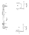
- FIG. 1 shows a tie rod in a one-part straight design, the ends of which can be connected to the steering levers of the steerable wheels of a motor vehicle by means of ball joints 1 and 2.
- the length of the tie rod is infinitely adjustable through interlocking components and in the case of the example fixable by means of a screwable clamp 3.
- such a tie rod is designed such that it buckles in the pressure direction when a predetermined load value is exceeded, as is shown graphically in diagram A in FIG.
- a securing element 4 is arranged in a section of the tie rod, which, due to its structural design, reacts when a predetermined load value is exceeded in the pulling direction and advantageously also in the pushing direction.
- This load value should be lower than the value of the breaking load of the components of the tie rod itself, as can be seen from a comparison of the load diagrams A and B. As a result, the components of the tie rod are protected against overstress by the securing member 4.
- This securing member 4 consists of a tubular outer part 5 and an inner part 6 engaging in it.
- the outer end of the outer part 5 is designed as a cuff 7, in which tongue-shaped tabs 7a are formed by longitudinally slot-like recesses and are bent back with a 180-degree bend.
- a sleeve 8 encloses the tabs 7a and is fastened at one end to the inner part 6, while the other end connects the tabs 7a to one another with a support ring 9.
- the ring 9 is axially slidably movable on the outer part 5, so that the inner part 6 with the sleeve 8 is axially displaceable relative to the outer part 5 with deformation of the tabs 7a, both in the pulling direction and in the pushing direction.
- the maximum load value of such a securing member acting in the axial direction can be determined by the material cross section of the tabs, by the hardness of the material used for these tabs, and possibly also by a friction fit of the ring 9 on the outer circumference of the outer part 5.
- the tabs 7a When overloaded in the direction of pull, the tabs 7a unwind against the outer circumference of the inner part 6 until they finally in Stretch position and prevent a further change in length, so that a limitation of the change in length is achieved.
- the tabs 7a wind up more tightly until the tabs 7 are supported on the sleeve 8 in the bending area and a limitation of the change in length is also achieved in this way.
- Switching pulses can also be triggered, which signal the driver of the motor vehicle the response of the safety element and thus the limited usability of the motor vehicle that has occurred.
Landscapes
- Engineering & Computer Science (AREA)
- Mechanical Engineering (AREA)
- Chemical & Material Sciences (AREA)
- Combustion & Propulsion (AREA)
- Transportation (AREA)
- Steering-Linkage Mechanisms And Four-Wheel Steering (AREA)
- Steering Controls (AREA)
- Vibration Dampers (AREA)
- Fittings On The Vehicle Exterior For Carrying Loads, And Devices For Holding Or Mounting Articles (AREA)
- Shafts, Cranks, Connecting Bars, And Related Bearings (AREA)
Description
Die Erfindung bezieht sich auf die Ausbildung einer Spurstange für Kraftfahrzeuge mit den Gattungsmerkmalen nach dem Oberbegriff des Patentanspruches 1.The invention relates to the design of a tie rod for motor vehicles with the generic features according to the preamble of claim 1.
Bekannt ist eine solche Spurstange aus der GB-A-2 050 271. Bei dieser bekannten Ausbildung besteht das Sicherungsglied aus Kunststoff. Es weist an der Innenseite umlaufende Nuten auf, in die vorspringende Wulstringe am Innenteil eingreifen. Die Haltekräfte zwischen dem Innenteil und dem Sicherungsglied sind dabei so definiert, daß bei einer Überschreitung dieser Haltekräfte das Innenteil in dem Sicherungsglied axial verrutscht. Daraus resultiert, daß diese bekannte Spurstange in dem Lastbereich unterhalb des Grenzwertes nicht starr sein kann. Diese Spurstange ist somit bei den heutigen Anforderungen im Automobilbau nicht tragbar.Such a tie rod is known from GB-A-2 050 271. In this known design, the securing member is made of plastic. It has circumferential grooves on the inside, into which protruding bead rings on the inner part engage. The holding forces between the inner part and the securing member are defined so that when these holding forces are exceeded, the inner part slips axially in the securing member. As a result, this known tie rod cannot be rigid in the load range below the limit. This tie rod is therefore not portable with today's requirements in automotive engineering.
Die EP-A- 0355 405 (Stand der Technik nach Art. 54(3) EPÜ) offenbart eine Spurstangenausbildung, bei der die Spurstange aus einem Rohr und aus einem in dieses Rohr mit dem einen Ende eingreifenden Stab besteht, der zwischen seiner Halterung in dem Rohr und dem Rohrende eine Sollbruchstelle und zwischen dieser Sollbruchstelle und dem Rohrende einen Absatz aufweist, wobei das Rohr zwischen dem Absatz und dem Rohrende mit einer Verengung versehen ist, die einen Anschlag für den Absatz beim Reißen der Sollbruchstelle bildet. Dadurch kann die Spurstange ihre Länge begrenzt verändern, wodurch das Fahrverhalten des Fahrzeuges nachhaltig verändert wird.EP-A-0355 405 (state of the art according to Art. 54 (3) EPC) discloses a tie rod design in which the tie rod consists of a tube and a rod which engages in this tube with one end, which is between has a predetermined breaking point in its holder in the tube and the tube end and a shoulder between this predetermined breaking point and the tube end, the tube being provided with a constriction between the paragraph and the tube end, which forms a stop for the paragraph when the predetermined breaking point tears. This allows the track rod to change its length to a limited extent, which permanently changes the driving behavior of the vehicle.
Spurstangen stellen ein für die Sicherheit des Fahrzeuges wesentliches Bauelement dar. Hohen Sicherheitsanforderungen stehen andererseits die Bestrebungen nach einem möglichst geringen Gewicht der Spurstange gegenüber. Bekannt ist die Vorausbestimmung einer gewissen Knickstabilität bei der Übertragung von Druckkräften, so daß die Spurstange oder ein Bauteil der Spurstange bei Überschreitung eines vorbestimmten Druckbelastungswertes ausknickt und dadurch andere, wesentlich teurere Bauteile vor einer Beschädigung schützt. In einem solchen Falle der Ausknickung, zum Beispiel bei Karambolagen mit einem anderen Fahrzeug, mit Verkehrseinrichtungen, Bauwerken oder dergleichen, ist das Kraftfahrzeug nicht mehr benutzbar.Tie rods represent an essential component for the safety of the vehicle. On the other hand, high safety requirements are offset by efforts to keep the tie rod as light as possible. It is known to predetermine a certain degree of kink stability during the transmission of compressive forces, so that the tie rod or a component of the tie rod buckles when a predetermined pressure load value is exceeded, thereby protecting other, much more expensive components from damage. In such a case of buckling, for example in the event of a collision with another vehicle, with traffic facilities, buildings or the like, the motor vehicle can no longer be used.
Der Erfindung liegt die Aufgabe zugrunde, eine unter Betriebsbelastungen axial starre Spurstange in der Weise weiterzubilden, daß sowohl eine Drucklastbegrenzung als auch eine Zuglastbegrenzung mit dem gleichen Sicherungsglied vorherbestimmbar ist und bei der dadurch ausgelösten Längenveränderung die in der Spurstange wirksamen Axialkräfte reduziert werden, um dadurch die Möglichkeit zu eröffnen, gegebenenfalls eine eingeschränkte Betriebsfähigkeit des Fahrzeuges aufrechtzuerhalten, wenn die Überlastsicherung wirksam geworden ist.The invention has for its object to develop a tie rod which is axially rigid under operating loads in such a way that both a pressure load limit and a tensile load limit can be predetermined using the same securing member and the axial forces effective in the tie rod are thereby reduced, thereby reducing the axial forces Possibility to open, if necessary, to maintain a limited operability of the vehicle when the overload protection has become effective.
Die Erfindung löst diese Aufgabe durch eine Ausbildung mit Merkmalen nach dem Patentanspruch 1.The invention solves this problem by training with features according to claim 1.
Durch diese Ausbildung des Sicherungsgliedes kann die Höchstbelastung einer unter Betriebsbedingungen axial starren Spurstange sowohl in Zug- als auch in Druckrichtung exakt definiert werden. Bei Überschreitung des vorbestimmten Höchstbelastungswertes erfolgt eine begrenzte Längenänderung der Spurstange, durch die ein erheblicher Teil der Überlastkräfte in Verformungskräfte in den Laschen umgesetzt wird, wobei die Spurstange als Bauteil erhalten bleibt und das Kraftfahrzeug unter mehr oder weniger eingeschränkten, in jedem Falle aber deutlich veränderten Bedingungen benutzbar ist.This design of the securing member allows the maximum load of a tie rod which is axially rigid under operating conditions to be precisely defined in both the pulling and pushing directions. If the predetermined maximum load value is exceeded, there is a limited change in the length of the tie rod, by means of which a considerable part of the overload forces are converted into deformation forces in the link plates, the tie rod being retained as a component and the motor vehicle under more or less restricted, but in any case significantly changed conditions is usable.
Ausführungsbeispiele der Erfindung sind auf der Zeichnung dargestellt. Es zeigen:
- Figur 1
- eine Seitenansicht einer Spurstange,
Figur 2- Belastungsdiagramme:
A einer herkömmlichen Spurstange
B einer erfindungsgemäßen Spurstange, - Figur 3
- einen im Maßstab vergrößerten Querschnitt des Sicherungsgliedes nach Figur 1 und
- Figur 4
- einen Schnitt nach der Linie IV - IV der Figur 3.
- Figure 1
- a side view of a tie rod,
- Figure 2
- Load diagrams:
A conventional tie rod
B a tie rod according to the invention, - Figure 3
- an enlarged cross-section of the securing member according to Figure 1 and
- Figure 4
- a section along the line IV - IV of Figure 3.
Die Figur 1 zeigt eine Spurstange in einteiliger gerader Ausbildung, deren Enden mittels Kugelgelenke 1 und 2 mit den Lenkhebeln der lenkbaren Räder eines Kraftfahrzeuges verbindbar sind. Die Länge der Spurstange ist durch ineinandergreifende Bauteile stufenlos einstellbar und im Falle des Beispieles mittels einer verschraubbaren Schelle 3 fixierbar. In herkömmlicher Ausbildung wird eine solche Spurstange so ausgelegt, daß sie bei Überschreitung eines vorbestimmten Belastungswertes in Druckrichtung ausknickt, wie es in dem Diagramm A der Figur 2 graphisch wiedergegeben ist.FIG. 1 shows a tie rod in a one-part straight design, the ends of which can be connected to the steering levers of the steerable wheels of a motor vehicle by means of
In einem Teilstück der Spurstange ist ein Sicherungsglied 4 angeordnet, welches aufgrund seiner baulichen Gestaltung bei Überschreitung eines vorbestimmten Belastungswertes in Zugrichtung und vorteilhaft auch in Druckrichtung reagiert. Dieser Belastungswert sollte niedriger sein als der Wert der Bruchbelastung der Bauteile der Spurstange an sich, wie es sich aus einem Vergleich der Belastungsdiagramme A und B ergibt. Dadurch werden die Bauteile der Spurstange durch das Sicherungsglied 4 gegen Überbeanspruchung geschützt.A securing element 4 is arranged in a section of the tie rod, which, due to its structural design, reacts when a predetermined load value is exceeded in the pulling direction and advantageously also in the pushing direction. This load value should be lower than the value of the breaking load of the components of the tie rod itself, as can be seen from a comparison of the load diagrams A and B. As a result, the components of the tie rod are protected against overstress by the securing member 4.
Dieses Sicherungsglied 4 besteht aus einem rohrförmigen Außenteil 5 und einem in dieses eingreifenden Innenteil 6. Das äußere Ende des Außenteiles 5 ist als Stulpe 7 ausgebildet, bei der durch längsschlitzartige Ausnehmungen zungenförmige Laschen 7a gebildet und mit einer 180-Grad-Biegung zurückgebogen sind. Eine Muffe 8 umschließt die Laschen 7a und ist mit dem einen Ende auf dem Innenteil 6 befestigt, während das andere Ende mit einem Stützring 9 die Laschen 7a miteinander verbindet. Der Ring 9 ist auf dem Außenteil 5 axial gleitend beweglich, so daß das Innenteil 6 mit der Muffe 8 unter Verformung der Laschen 7a axial gegenüber dem Außenteil 5 verschieblich ist, und zwar sowohl in Zugrichtung als auch in Druckrichtung. Der maximale Belastungswert eines solchen in axialer Richtung wirkenden Sicherungsgliedes ist durch den Materialquerschnitt der Laschen, durch die Härte des für diese Laschen verwendeten Werkstoffes und gegebenenfalls auch durch einen Reibsitz des Ringes 9 auf dem Außenumfang des Außenteiles 5 bestimmbar. Bei Überlastung in Zugrichtung wickeln sich die Laschen 7a gegen den Außenumfang des Innenteiles 6 ab, bis sie schließlich in Strecklage gelangen und eine weitere Längenänderung verhindern, so daß eine Begrenzung der Längenänderung erreicht wird. Bei Überlastung in Druckrichtung wickeln sich die Laschen 7a stärker auf, bis sich die Laschen 7 im Biegebereich an der Muffe 8 abstützen und so ebenfalls eine Begrenzung der Längenänderung erreicht wird. Dabei können auch Schaltimpulse ausgelöst werden, die dem Führer des Kraftfahrzeuges das Ansprechen des Sicherungsgliedes und damit die eingetretene beschränkte Benutzbarkeit des Kraftfahrzeuges signalisieren.This securing member 4 consists of a tubular
Claims (1)
- A track rod for motor vehicles with a safety member which is effective in the longitudinal direction of the vehicle and which can be altered to a limited degree in its length when a defined, axially acting loading value is exceeded, the safety member comprising a tubular outer part (5) and an inner part (6) engaging coaxially in the outer part, the two parts engaging in one another by means of radially directed moulded parts (7) and limiting the reciprocal axial movement, the outer part (5) and the inner part (6) together forming the track rod and being connected with one another in an axially positive-locking manner, and the axial loadability of the said axially positive-locking connection being adjusted to the defined loading value and the axially positive-locking connection yielding once the defined loading value is exceeded, characterised in that a sleeve (8) secured to the inner part encloses the end of the inner part (6) and, within the sleeve, the brackets (7a) forming the moulded parts are secured with one end to the outer part (5), whilst the other end of the brackets is bent back with a 180-degree curvature and is supported axially against the sleeve
Applications Claiming Priority (2)
| Application Number | Priority Date | Filing Date | Title |
|---|---|---|---|
| DE3915991A DE3915991A1 (en) | 1989-05-17 | 1989-05-17 | TRACK ROD FOR MOTOR VEHICLES |
| DE3915991 | 1989-05-17 |
Publications (2)
| Publication Number | Publication Date |
|---|---|
| EP0399253A1 EP0399253A1 (en) | 1990-11-28 |
| EP0399253B1 true EP0399253B1 (en) | 1993-08-04 |
Family
ID=6380784
Family Applications (1)
| Application Number | Title | Priority Date | Filing Date |
|---|---|---|---|
| EP90108292A Expired - Lifetime EP0399253B1 (en) | 1989-05-17 | 1990-05-02 | Track rod for motor vehicles |
Country Status (7)
| Country | Link |
|---|---|
| US (1) | US5104136A (en) |
| EP (1) | EP0399253B1 (en) |
| JP (1) | JPH0757615B2 (en) |
| KR (1) | KR940009857B1 (en) |
| BR (1) | BR9002289A (en) |
| DE (1) | DE3915991A1 (en) |
| ES (1) | ES2043173T3 (en) |
Families Citing this family (26)
| Publication number | Priority date | Publication date | Assignee | Title |
|---|---|---|---|---|
| US5178167A (en) * | 1991-06-28 | 1993-01-12 | R. J. Reynolds Tobacco Company | Carbonaceous composition for fuel elements of smoking articles and method of modifying the burning characteristics thereof |
| US6074125A (en) * | 1998-06-26 | 2000-06-13 | Chrysler Corporation | Tie rod assemble for a motor vehicle and related method |
| US6193612B1 (en) * | 1998-08-10 | 2001-02-27 | Ford Global Technologies, Inc. | Collapsible driveshaft |
| JP2001353379A (en) * | 2000-06-15 | 2001-12-25 | Nikko:Kk | Remote-controlled running toy |
| DE10032711C2 (en) * | 2000-07-07 | 2003-04-30 | Torsten Wiche | Divisible tie rod for motor vehicles |
| US20070166096A1 (en) * | 2005-06-03 | 2007-07-19 | Lim Chong K | Joint assembly |
| US7547028B1 (en) | 2007-01-08 | 2009-06-16 | Trw Automotive U.S. Llc | Tie rod steering linkage |
| JP2009024858A (en) * | 2007-07-24 | 2009-02-05 | Yamaha Motor Co Ltd | Automatic shift control device, power unit with the same, and saddle-riding type vehicle |
| DE102008000936B4 (en) | 2008-04-02 | 2014-04-10 | Zf Friedrichshafen Ag | Wheel suspension for a vehicle and connecting element for such a suspension |
| DE102009046894A1 (en) | 2009-11-20 | 2011-05-26 | Zf Friedrichshafen Ag | Handlebar element with overload protection |
| US8714571B2 (en) * | 2010-03-16 | 2014-05-06 | Automann Inc. | Torque rod |
| DE102010043778A1 (en) | 2010-11-11 | 2012-05-16 | Zf Friedrichshafen Ag | Handlebar element with overload protection |
| CN103402858A (en) | 2011-02-03 | 2013-11-20 | 帝人株式会社 | Vehicle skeleton member |
| DE102011007390A1 (en) * | 2011-04-14 | 2012-10-18 | Zf Friedrichshafen Ag | chassis component |
| US8702112B1 (en) * | 2011-05-10 | 2014-04-22 | Trw Automotive U.S. Llc | Steering linkage and method for producing same |
| US8770602B1 (en) * | 2011-05-10 | 2014-07-08 | Trw Automotive U.S. Llc | Steering linkage and method for producing same |
| DE102011079267A1 (en) | 2011-07-15 | 2013-01-17 | Zf Friedrichshafen Ag | Ball joint with overload protection, particularly for wheel suspensions or steering system, has joint housing and bearing pin that is provided with ball portion and shaft portion, where catching element is provided with recess |
| DE102011111842B4 (en) | 2011-08-27 | 2013-04-04 | Audi Ag | ball joint |
| DE102012018554B3 (en) * | 2012-09-20 | 2014-02-13 | Audi Ag | Handlebar for a wheel suspension of a motor vehicle |
| DE102013004010B4 (en) | 2013-03-08 | 2016-02-18 | Audi Ag | Achslenker for a motor vehicle |
| US20150056001A1 (en) * | 2013-08-22 | 2015-02-26 | Powers and Sons, LLC | Mechanical overload fuse for steering linkage |
| BR102015032840B1 (en) * | 2015-12-29 | 2022-01-11 | Embraco Indústria De Compressores E Soluções Em Refrigeração Ltda | TELESCOPIC TWO-START ROD ROD FOR ALTERNATIVE COMPRESSORS AND TELESCOPIC TWO-START ROD MOUNTING METHOD IN ALTERNATIVE COMPRESSORS |
| US9821843B1 (en) * | 2017-01-06 | 2017-11-21 | Robert Bosch Automotive Steering Llc | Tie rod |
| USD862305S1 (en) * | 2017-01-30 | 2019-10-08 | Stemco Products, Inc. | Center link assembly |
| USD853283S1 (en) * | 2017-01-30 | 2019-07-09 | Stemco Products, Inc. | Center link assembly |
| US11964719B2 (en) | 2020-08-20 | 2024-04-23 | Toyota Motor Engineering & Manufacturing North America, Inc. | Breakaway automotive steering tie rod for controlled wheel motion during crash |
Family Cites Families (19)
| Publication number | Priority date | Publication date | Assignee | Title |
|---|---|---|---|---|
| DE882512C (en) * | 1948-12-30 | 1956-11-29 | Ehrenreich & Cie A | Steering linkages for motor vehicles |
| US2857056A (en) * | 1955-05-02 | 1958-10-21 | Gen Motors Corp | Coupling assembly |
| US2803970A (en) * | 1956-05-01 | 1957-08-27 | Sacks Morris | Collapsible steering column |
| US3434369A (en) * | 1965-08-05 | 1969-03-25 | Bendix Corp | No-lash axially movable steering column |
| US3479902A (en) * | 1966-11-10 | 1969-11-25 | Nippon Seiko Kk | Safety steering assembly |
| US3504567A (en) * | 1967-05-25 | 1970-04-07 | Toyota Motor Co Ltd | Collapsible steering shaft construction |
| ES159569Y (en) * | 1970-06-19 | 1971-03-16 | Navarro Escudero | SECURITY DIRECTION FOR AUTOMOBILE VEHICLES. |
| GB1351780A (en) * | 1971-07-27 | 1974-05-01 | Ford Motor Co | Collapsible steering column for a motor vehicle |
| US3741032A (en) * | 1971-09-27 | 1973-06-26 | Bendix Corp | Collapsible steering column assembly |
| US3776062A (en) * | 1972-04-19 | 1973-12-04 | K Ito | Shock absorbing steering shaft assembly |
| JPS49128415A (en) * | 1973-04-16 | 1974-12-09 | ||
| US3988818A (en) * | 1975-07-07 | 1976-11-02 | Ford Motor Company | Tie rod end |
| DE2920637A1 (en) * | 1979-05-22 | 1980-12-04 | Volkswagenwerk Ag | DEVICE FOR PROTECTING A STEERING GEARBOX AGAINST IMPULSE OVERLOAD |
| GB2059006A (en) * | 1979-08-02 | 1981-04-15 | Accles & Pollock Ltd | Energy-absorbing steering columns |
| AT372314B (en) * | 1981-07-03 | 1983-09-26 | Supervis Ets | STEERING SPINDLE FOR STEERING DEVICES IN MOTOR VEHICLES |
| DE3202669A1 (en) * | 1982-01-28 | 1983-08-04 | Reiche & Co, 4937 Lage | TELESCOPIC TUBE, ESPECIALLY FOR A HEIGHT-ADJUSTABLE MOTOR VEHICLE STEERING COLUMN AND METHOD FOR ESTABLISHING A SLIDING CONNECTION BETWEEN THE INNER TUBE AND THE OUTER TUBE OF THE TELESCOPIC TUBE |
| US4674354A (en) * | 1985-10-15 | 1987-06-23 | Brand Harold E | Collapsible steering column |
| GB2200488A (en) * | 1987-01-31 | 1988-08-03 | Ford Motor Co | A steering column arrangement in a motor vehicle |
| DE3827854C1 (en) * | 1988-08-17 | 1989-12-28 | Trw Ehrenreich Gmbh & Co Kg, 4000 Duesseldorf, De |
-
1989
- 1989-05-17 DE DE3915991A patent/DE3915991A1/en active Granted
-
1990
- 1990-05-02 ES ES90108292T patent/ES2043173T3/en not_active Expired - Lifetime
- 1990-05-02 EP EP90108292A patent/EP0399253B1/en not_active Expired - Lifetime
- 1990-05-14 KR KR1019900006816A patent/KR940009857B1/en not_active IP Right Cessation
- 1990-05-16 BR BR909002289A patent/BR9002289A/en not_active IP Right Cessation
- 1990-05-16 US US07/524,151 patent/US5104136A/en not_active Expired - Fee Related
- 1990-05-17 JP JP2125621A patent/JPH0757615B2/en not_active Expired - Fee Related
Also Published As
| Publication number | Publication date |
|---|---|
| ES2043173T3 (en) | 1993-12-16 |
| KR900017860A (en) | 1990-12-20 |
| JPH0757615B2 (en) | 1995-06-21 |
| US5104136A (en) | 1992-04-14 |
| JPH0310973A (en) | 1991-01-18 |
| DE3915991A1 (en) | 1990-11-22 |
| BR9002289A (en) | 1991-08-06 |
| EP0399253A1 (en) | 1990-11-28 |
| KR940009857B1 (en) | 1994-10-18 |
| DE3915991C2 (en) | 1991-05-16 |
Similar Documents
| Publication | Publication Date | Title |
|---|---|---|
| EP0399253B1 (en) | Track rod for motor vehicles | |
| EP0943525B1 (en) | Steering column arrangement for a motor vehicle | |
| DE4026459A1 (en) | DOOR AMPLIFIER PIPE | |
| DE1755006B2 (en) | Plastic deformable impact absorber for vehicles | |
| DE3827854C1 (en) | ||
| DE19504036C1 (en) | Safety steering shaft | |
| DE1950062A1 (en) | Steering device | |
| EP2807071B1 (en) | Steering column for a motor vehicle | |
| DE2108913B2 (en) | Rod or shaft, in particular steering shaft for motor vehicles, and method for their production | |
| DE2460598A1 (en) | Impact absorbing telescopic tubes on car - are radially expanded by tapered ram on impact | |
| DE69713829T2 (en) | Steering column device absorbing impact energy, in particular for a motor vehicle | |
| DE2419193A1 (en) | Shock absorber for car shoulder seat belt - has strap buckled round plastically-deformable energy absorbing coil spring | |
| DE3427211C1 (en) | Safety steering column for motor vehicles | |
| DE102008000936A1 (en) | Wheel suspension for vehicle i.e. motor vehicle, has two wheel suspension components e.g. axle carrier and control arm, and connection element connecting wheel suspension components in energy-absorbing and articulated manner | |
| EP0749886B1 (en) | Safety steering column | |
| CH687607A5 (en) | Vehicle seat. | |
| DE29602072U1 (en) | Device for absorbing impact energy and for suspending a bumper on a vehicle | |
| DE4227967A1 (en) | Tube-shaped structural metal part for vehicle - has roof-shaped zone deformable in event of impact | |
| WO2002018816A1 (en) | Device for absorbing impact force | |
| DE2357713A1 (en) | FOLDABLE STEERING COLUMN FOR MOTOR VEHICLES | |
| EP1113955B1 (en) | Steering shaft | |
| DE2621983A1 (en) | Anchoring fitting for seat belt - has cable extending from buckle and fitted with plunger element which deforms nut | |
| DE1630825A1 (en) | Safety steering for cars | |
| DE2106963C3 (en) | Console for carrying a jacket pipe for a safety steering of a motor vehicle | |
| DE2044874C3 (en) | Safety steering column |
Legal Events
| Date | Code | Title | Description |
|---|---|---|---|
| PUAI | Public reference made under article 153(3) epc to a published international application that has entered the european phase |
Free format text: ORIGINAL CODE: 0009012 |
|
| AK | Designated contracting states |
Kind code of ref document: A1 Designated state(s): ES FR GB IT SE |
|
| 17P | Request for examination filed |
Effective date: 19901112 |
|
| 17Q | First examination report despatched |
Effective date: 19910625 |
|
| GRAA | (expected) grant |
Free format text: ORIGINAL CODE: 0009210 |
|
| AK | Designated contracting states |
Kind code of ref document: B1 Designated state(s): ES FR GB IT SE |
|
| GBT | Gb: translation of ep patent filed (gb section 77(6)(a)/1977) |
Effective date: 19930823 |
|
| ET | Fr: translation filed | ||
| ITF | It: translation for a ep patent filed | ||
| REG | Reference to a national code |
Ref country code: ES Ref legal event code: FG2A Ref document number: 2043173 Country of ref document: ES Kind code of ref document: T3 |
|
| PGFP | Annual fee paid to national office [announced via postgrant information from national office to epo] |
Ref country code: ES Payment date: 19940414 Year of fee payment: 5 |
|
| PGFP | Annual fee paid to national office [announced via postgrant information from national office to epo] |
Ref country code: FR Payment date: 19940420 Year of fee payment: 5 |
|
| PGFP | Annual fee paid to national office [announced via postgrant information from national office to epo] |
Ref country code: GB Payment date: 19940421 Year of fee payment: 5 |
|
| PGFP | Annual fee paid to national office [announced via postgrant information from national office to epo] |
Ref country code: SE Payment date: 19940509 Year of fee payment: 5 |
|
| PLBE | No opposition filed within time limit |
Free format text: ORIGINAL CODE: 0009261 |
|
| STAA | Information on the status of an ep patent application or granted ep patent |
Free format text: STATUS: NO OPPOSITION FILED WITHIN TIME LIMIT |
|
| 26N | No opposition filed | ||
| EAL | Se: european patent in force in sweden |
Ref document number: 90108292.5 |
|
| PG25 | Lapsed in a contracting state [announced via postgrant information from national office to epo] |
Ref country code: GB Effective date: 19950502 |
|
| PG25 | Lapsed in a contracting state [announced via postgrant information from national office to epo] |
Ref country code: SE Effective date: 19950503 Ref country code: ES Free format text: LAPSE BECAUSE OF NON-PAYMENT OF DUE FEES Effective date: 19950503 |
|
| GBPC | Gb: european patent ceased through non-payment of renewal fee |
Effective date: 19950502 |
|
| EUG | Se: european patent has lapsed |
Ref document number: 90108292.5 |
|
| PG25 | Lapsed in a contracting state [announced via postgrant information from national office to epo] |
Ref country code: FR Effective date: 19960229 |
|
| REG | Reference to a national code |
Ref country code: FR Ref legal event code: ST |
|
| REG | Reference to a national code |
Ref country code: FR Ref legal event code: ST |
|
| REG | Reference to a national code |
Ref country code: ES Ref legal event code: FD2A Effective date: 19990201 |
|
| PG25 | Lapsed in a contracting state [announced via postgrant information from national office to epo] |
Ref country code: IT Free format text: LAPSE BECAUSE OF NON-PAYMENT OF DUE FEES;WARNING: LAPSES OF ITALIAN PATENTS WITH EFFECTIVE DATE BEFORE 2007 MAY HAVE OCCURRED AT ANY TIME BEFORE 2007. THE CORRECT EFFECTIVE DATE MAY BE DIFFERENT FROM THE ONE RECORDED. Effective date: 20050502 |