EP0399253A1 - Track rod for motor vehicles - Google Patents
Track rod for motor vehicles Download PDFInfo
- Publication number
- EP0399253A1 EP0399253A1 EP90108292A EP90108292A EP0399253A1 EP 0399253 A1 EP0399253 A1 EP 0399253A1 EP 90108292 A EP90108292 A EP 90108292A EP 90108292 A EP90108292 A EP 90108292A EP 0399253 A1 EP0399253 A1 EP 0399253A1
- Authority
- EP
- European Patent Office
- Prior art keywords
- tie rod
- inner part
- outer part
- load value
- rod according
- Prior art date
- Legal status (The legal status is an assumption and is not a legal conclusion. Google has not performed a legal analysis and makes no representation as to the accuracy of the status listed.)
- Granted
Links
- 230000008859 change Effects 0.000 claims description 19
- 239000011324 bead Substances 0.000 claims description 9
- 230000004323 axial length Effects 0.000 claims description 2
- 238000006073 displacement reaction Methods 0.000 claims 2
- 208000000260 Warts Diseases 0.000 description 10
- 201000010153 skin papilloma Diseases 0.000 description 10
- 238000010586 diagram Methods 0.000 description 7
- 239000000463 material Substances 0.000 description 6
- 230000004044 response Effects 0.000 description 3
- 238000000418 atomic force spectrum Methods 0.000 description 2
- 230000006378 damage Effects 0.000 description 2
- 230000000694 effects Effects 0.000 description 2
- 230000009467 reduction Effects 0.000 description 2
- 230000001960 triggered effect Effects 0.000 description 2
- 241001295925 Gegenes Species 0.000 description 1
- 230000009471 action Effects 0.000 description 1
- 239000012237 artificial material Substances 0.000 description 1
- 238000005452 bending Methods 0.000 description 1
- 230000005540 biological transmission Effects 0.000 description 1
- 230000000903 blocking effect Effects 0.000 description 1
- 150000001875 compounds Chemical class 0.000 description 1
- 239000007788 liquid Substances 0.000 description 1
- 239000007769 metal material Substances 0.000 description 1
- 230000000717 retained effect Effects 0.000 description 1
- 238000010008 shearing Methods 0.000 description 1
- 239000000243 solution Substances 0.000 description 1
Images


Classifications
-
- B—PERFORMING OPERATIONS; TRANSPORTING
- B60—VEHICLES IN GENERAL
- B60G—VEHICLE SUSPENSION ARRANGEMENTS
- B60G7/00—Pivoted suspension arms; Accessories thereof
- B60G7/001—Suspension arms, e.g. constructional features
-
- B—PERFORMING OPERATIONS; TRANSPORTING
- B62—LAND VEHICLES FOR TRAVELLING OTHERWISE THAN ON RAILS
- B62D—MOTOR VEHICLES; TRAILERS
- B62D1/00—Steering controls, i.e. means for initiating a change of direction of the vehicle
- B62D1/02—Steering controls, i.e. means for initiating a change of direction of the vehicle vehicle-mounted
- B62D1/12—Hand levers
-
- B—PERFORMING OPERATIONS; TRANSPORTING
- B62—LAND VEHICLES FOR TRAVELLING OTHERWISE THAN ON RAILS
- B62D—MOTOR VEHICLES; TRAILERS
- B62D7/00—Steering linkage; Stub axles or their mountings
- B62D7/20—Links, e.g. track rods
-
- B—PERFORMING OPERATIONS; TRANSPORTING
- B60—VEHICLES IN GENERAL
- B60G—VEHICLE SUSPENSION ARRANGEMENTS
- B60G2206/00—Indexing codes related to the manufacturing of suspensions: constructional features, the materials used, procedures or tools
- B60G2206/01—Constructional features of suspension elements, e.g. arms, dampers, springs
- B60G2206/016—Constructional features of suspension elements, e.g. arms, dampers, springs allowing controlled deformation during collision
-
- B—PERFORMING OPERATIONS; TRANSPORTING
- B60—VEHICLES IN GENERAL
- B60G—VEHICLE SUSPENSION ARRANGEMENTS
- B60G2206/00—Indexing codes related to the manufacturing of suspensions: constructional features, the materials used, procedures or tools
- B60G2206/01—Constructional features of suspension elements, e.g. arms, dampers, springs
- B60G2206/10—Constructional features of arms
- B60G2206/11—Constructional features of arms the arm being a radius or track or torque or steering rod or stabiliser end link
-
- F—MECHANICAL ENGINEERING; LIGHTING; HEATING; WEAPONS; BLASTING
- F16—ENGINEERING ELEMENTS AND UNITS; GENERAL MEASURES FOR PRODUCING AND MAINTAINING EFFECTIVE FUNCTIONING OF MACHINES OR INSTALLATIONS; THERMAL INSULATION IN GENERAL
- F16B—DEVICES FOR FASTENING OR SECURING CONSTRUCTIONAL ELEMENTS OR MACHINE PARTS TOGETHER, e.g. NAILS, BOLTS, CIRCLIPS, CLAMPS, CLIPS OR WEDGES; JOINTS OR JOINTING
- F16B2200/00—Constructional details of connections not covered for in other groups of this subclass
- F16B2200/63—Frangible connections
Definitions
- the invention relates to the design of a tie rod for motor vehicles with the generic features according to the preamble of claim 1.
- DE-PS 38 27 854 describes such a tie rod design, in which the tie rod consists of a tube and a rod engaging in this tube with one end, which has a predetermined breaking point between its holder in the tube and the tube end and between this predetermined breaking point and the pipe end has a shoulder, the pipe being provided between the shoulder and the pipe end with a constriction which forms a stop for the shoulder when the predetermined breaking point is torn.
- This allows the track rod to change its length to a limited extent, which permanently changes the driving behavior of the vehicle.
- Tie rods are an essential component for the safety of the vehicle
- safety requirements are offset by efforts to keep the tie rod as light as possible. It is known to predetermine a certain degree of kink stability during the transmission of compressive forces, so that the tie rod or a component of the tie rod buckles when a predetermined pressure load value is exceeded, thereby protecting other, much more expensive components from damage.
- buckling for example in the event of a collision with another vehicle, with traffic facilities, buildings or the like, the motor vehicle can no longer be used.
- the invention has for its object to develop a tie rod in such a way that both a pressure load limit and a tensile load limit can be predetermined with the same securing member and the axial forces effective in the tie rod are reduced in the length change thereby triggered, thereby opening up the possibility of if necessary, maintain a limited operational capability of the vehicle when the overload protection has taken effect.
- the invention solves this problem by training with features according to the characterizing part of patent claim 1.
- This design of the securing element allows the maximum load on the tie rod to be precisely defined in both the pulling and pushing directions.
- the positive connection of the tubular outer part and the inner part engaging in this can be achieved by cutting, non-cutting deformation, press fit training or the like can be achieved in a manner known per se.
- the tie rod when the predetermined maximum load value is exceeded, there is a limited change in the length of the tie rod, by means of which a considerable part of the overload forces is converted into deformation forces or frictional forces, so that the tie rod is retained as a component and the motor vehicle is more or less restricted, in any case but clearly changed conditions can be used.
- the limited change in length of the tie rod must lead to a clear indication of the restricted usability of the motor vehicle, either to indicate this restricted usability to the driver of the vehicle or to make it impossible to use the motor vehicle outside of restricted conditions.
- the means for limiting the axial change in length of the tie rod are designed so that much higher overload forces are required to overcome them. This makes it possible to locate the response of the securing member in an area which is below the load value for a possible buckling of the tie rod or for a breakage of the tie rod itself.
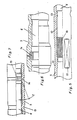
- FIG. 1 shows a tie rod in a one-part straight design, the ends of which can be connected to the steering levers of the steerable wheels of a motor vehicle by means of ball joints 1 and 2.
- the length of the tie rod is infinitely adjustable by means of interlocking components and, in the example, can be fixed by means of a screwable clamp 3.
- such a tie rod is designed such that it bends in the pressure direction when a predetermined load value is exceeded, as is shown graphically in diagram A in FIG.
- a securing element 4 is arranged in a section of the tie rod, which, due to its structural design, advantageously and advantageously also when a predetermined load value in the pulling direction is exceeded reacts in the printing direction.
- This load value should be lower than the value of the breaking load of the components of the tie rod itself, as can be seen from a comparison of the load diagrams A and B. As a result, the components of the tie rod are protected against overstress by the securing member 4.
- this securing element 4 consists of a tubular outer part 5 and an inner part 6 engaging in it.
- the outer end of the outer part 5 is designed as a cuff 7, in which tongue-shaped tabs 7a are formed by longitudinally slot-like recesses and are provided with a 180- Degrees bend are bent back.
- a sleeve 8 encloses the tabs 7a and is fastened at one end to the inner part 6, while the other end connects the tabs 7 to one another with a support ring 9.
- the ring 9 is axially slidably movable on the outer part 5, so that the inner part 6 with the sleeve 8 is axially displaceable relative to the outer part 5 while deforming the tabs 7, both in the pulling direction and in the pushing direction.
- the maximum load value of such a securing member acting in the axial direction can be determined by the material cross section of the tabs, by the hardness of the material used for these tabs, and possibly also by a friction fit of the ring 9 on the outer circumference of the outer part 5.
- a press-fit design 10 is provided over a limited length range of the inner part 6 and cooperates with a corresponding design on the inner circumference of the outer part 5.
- the length and surface structure of the press fit surfaces are aligned with the maximum load value so that the press fit is released when this load value is exceeded.
- a grooved or knurled surface is shown on the inner part and a partial pressing 11 is provided, by means of which the press fit connection of the two parts is achieved.
- the inner part 6 is provided with a longitudinally arranged recess 12 or with a plurality of recesses distributed over the circumference, into which a wart 13 or the like engages, which is pressed into the outer part 5 from the outside.
- FIG. 6 shows an exemplary embodiment in which a securing ring 14 designed for shearing is arranged between the outer part 5 and the inner part 6.
- This locking ring 14 can consist of an automatically hardening filling compound which is introduced in liquid form into an annular groove formed by the outer part 5 and the inner part 6 between the two parts.
- the shear cross section in the event of an axial overload can easily be calculated on the basis of the data known for the material.
- a wart 13 of the outer part engages in a longitudinal groove 12 of the inner part, in order thereby to limit the change in length of the tie rod when the ring 14 is sheared off.
- FIG. 7 shows an exemplary embodiment in which a tubular outer part 5 and a wave-shaped inner part 6 engage in one another by non-cutting or cutting deformations.
- a radially recessed groove 15 is shown on the circumference of the inner part 6, so that a bead 16 pressed into the groove 15 from the outside results in a positive connection in which the angular positions b of the flanks of the groove 15 can be used to determine the maximum load value. If this load value is exceeded, the bead 16 slides out of the groove 15, deforming the outer part 5, so that the outer part and the inner part are axially movable relative to one another.
- axially transferable loads are functions of the angle b and the properties of the material of the outer part 5 as well as its dimensioning.
- Figures 8 and 9 show comparable configurations as the example in Figure 7, but with a different force profile.
- the latter corresponds approximately to diagram B in FIG. 2 in the arrangement according to FIG. 7, while the force curve in the arrangement according to FIGS. 8 and 9 approximately follows diagram C in FIG.
- the deformations of the outer part 5 are more punctiform in the latter examples, so that only wart-like projections on the inner circumference of the outer part 5 engage either in the circumferential groove 15 or in the longitudinally arranged groove 12 of the inner part 6.
- the inner part 6 and the outer part 5 in the area between the warts 13 and the bead 16 can have a polygonal cross section and can be radially pressed together.
- FIGS. 10 and 11 show an example in which the warts 13 engage in a circumferential reduction in diameter of the inner part 6, so that a radial deformation of the outer part 5 enables the securing member to respond both in the pulling direction and in the pushing direction.
- the connection between the outer part 5 and the inner part 6 required for transmitting an axial force is achieved by torsion spring forces.
- the inner part 6 or the outer part 5 are effective as a torsion spring. Both parts interlock with a polygonal cross-section, which at least is formed in axially limited areas on collars 17 of the inner part and engages in staggered polygons on the inner circumference of the outer part.
- the axially positive connection is achieved by one or more spring elements 18, which are arranged either on the inner circumference of the outer part 5 or on the outer circumference of the inner part 6.
- FIG. 8 A combination of the design according to FIGS. 8 and 9 with a design according to FIG. 12 is described in FIG.
- An axially positive engagement of a bead 16 in a circumferential groove 15 of the inner part 6 is offset from a positive connection of the outer part 5 to the inner part 6 by spring element 18, the effect of which has been explained in relation to FIG.
- a bead 16 pressed into the outer part from the outside engages in a region of reduced diameter, so that the Axial movement in the pressure direction of the inner part 6 relative to the outer part 5 is limited by the length of this area with a reduced diameter.
- the change in length in the direction of pull is limited by circumferential groove 17.
- FIG. 14 shows an example in which, in addition to the means for the positive connection of the inner part 6 and the outer part 5, a contact for triggering a signal is provided by an all-round groove 15 on the circumference of the inner part and a bead 16 embossed from the outside is provided, which signals the response of the securing member to the driver in any way.
- a contact body 19 is shown in a line 20 which is torn when the tie rod changes its axial length, so that the line 20 is interrupted.
- This contact body 19 can also be designed so that it triggers a signal in the pressure direction, for example by changing its resistance, which is perceptibly transmitted by the vehicle driver.
- a signal transmitter according to this exemplary embodiment can be attached, for example glued, with its housing parts 21 and 22 on the one hand to the outer part 5 and on the other hand to the inner part 6.
- FIG. 15 shows an exemplary embodiment in which, between the tubular outer part 5 and the inner part 6, a lock blocking the return of both parts to the starting position after the axial change in length is made up of one or also of several wedge segments 23 arranged on the circumference, its or whose wedge surfaces cooperate with counter surfaces on the outer part 5 and on the inner part 6, so that both parts are clamped together by wedge action when they move in the opposite direction after a change in length.
- the entrainment of the wedge segment or segments 23 when the length changes takes place through edge deformations 24 which engage behind the wedge segment or segments 23.
- the wedge segments 23 can consist of a metallic or artificial material.
- the lock consists of a spring 25, which encloses the inner part 6 and, if the outer part 5 and the inner part 6 return movement, returns to the starting position after a change in length between the two parts spreads and thereby jammed both parts together.
- a spring 25 which encloses the inner part 6 and, if the outer part 5 and the inner part 6 return movement, returns to the starting position after a change in length between the two parts spreads and thereby jammed both parts together.
- Both a disc spring and a spiral spring are suitable for this.
- Such a spring is also held by an edge deformation 24 in the recess provided for receiving the spring.
Abstract
Description
Die Erfindung bezieht sich auf die Ausbildung einer Spurstange für Kraftfahrzeuge mit den Gattungsmerkmalen nach dem Oberbegriff des Patentanspruches 1.The invention relates to the design of a tie rod for motor vehicles with the generic features according to the preamble of claim 1.
Die DE-PS 38 27 854 beschreibt eine solche Spurstangenausbildung, bei der die Spurstange aus einem Rohr und aus einem in dieses Rohr mit dem einen Ende eingreifenden Stab besteht, der zwischen seiner Halterung in dem Rohr und dem Rohrende eine Sollbruchstelle und zwischen dieser Sollbruchstelle und dem Rohrende einen Absatz aufweist, wobei das Rohr zwischen dem Absatz und dem Rohrende mit einer Verengung versehen ist, die einen Anschlag für den Absatz beim Reißen der Sollbruchstelle bildet. Dadurch kann die Spurstange ihre Länge begrenzt verändern, wodurch das Fahrverhalten des Fahrzeuges nachhaltig verändert wird.DE-PS 38 27 854 describes such a tie rod design, in which the tie rod consists of a tube and a rod engaging in this tube with one end, which has a predetermined breaking point between its holder in the tube and the tube end and between this predetermined breaking point and the pipe end has a shoulder, the pipe being provided between the shoulder and the pipe end with a constriction which forms a stop for the shoulder when the predetermined breaking point is torn. This allows the track rod to change its length to a limited extent, which permanently changes the driving behavior of the vehicle.
Spurstangen stellen ein für die Sicherheit des Fahrzeuges wesentliches Bauelement dar. Hohen Sicherheitsanforderungen stehen andererseits die Bestrebungen nach einem möglichst geringen Gewicht der Spurstange gegenüber. Bekannt ist die Vorausbestimmung einer gewissen Knickstabilität bei der Übertragung von Druckkräften, so daß die Spurstange oder ein Bauteil der Spurstange bei Überschreitung eines vorbestimmten Druckbelastungswertes ausknickt und dadurch andere, wesentlich teurere Bauteile vor einer Beschädigung schützt. In einem solchen Falle der Ausknickung, zum Beispiel bei Karambolagen mit einem anderen Fahrzeug, mit Verkehrseinrichtungen, Bauwerken oder dergleichen, ist das Kraftfahrzeug nicht mehr benutzbar.Tie rods are an essential component for the safety of the vehicle On the other hand, safety requirements are offset by efforts to keep the tie rod as light as possible. It is known to predetermine a certain degree of kink stability during the transmission of compressive forces, so that the tie rod or a component of the tie rod buckles when a predetermined pressure load value is exceeded, thereby protecting other, much more expensive components from damage. In such a case of buckling, for example in the event of a collision with another vehicle, with traffic facilities, buildings or the like, the motor vehicle can no longer be used.
Der Erfindung liegt die Aufgabe zugrunde, eine Spurstange in der Weise weiterzubilden, daß sowohl eine Drucklastbegrenzung als auch eine Zuglastbegrenzung mit dem gleichen Sicherungsglied vorherbestimmbar ist und bei der dadurch ausgelösten Längenveränderung die in der Spurstange wirksamen Axialkräfte reduziert werden, um dadurch die Möglichkeit zu eröffnen, gegebenenfalls eine eingeschränkte Betriebsfähigkeit des Fahrzeuges aufrechtzuerhalten, wenn die Überlastsicherung wirksam geworden ist.The invention has for its object to develop a tie rod in such a way that both a pressure load limit and a tensile load limit can be predetermined with the same securing member and the axial forces effective in the tie rod are reduced in the length change thereby triggered, thereby opening up the possibility of if necessary, maintain a limited operational capability of the vehicle when the overload protection has taken effect.
Die Erfindung löst diese Aufgabe durch eine Ausbildung mit Merkmalen nach dem Kennzeichen des Patentanspruches 1.The invention solves this problem by training with features according to the characterizing part of patent claim 1.
Durch diese Ausbildung des Sicherungsgliedes kann die Höchstbelastung der Spurstange sowohl in Zug- als auch in Druckrichtung exakt definiert werden. Die formschlüssige Verbindung des rohrförmigen Außenteils und des in dieses eingreifenden Innenteils kann durch spanende, spanlose Verformung, Preßsitzausbildungen oder dergleichen in an sich bekannter Weise erreicht werden.This design of the securing element allows the maximum load on the tie rod to be precisely defined in both the pulling and pushing directions. The positive connection of the tubular outer part and the inner part engaging in this can be achieved by cutting, non-cutting deformation, press fit training or the like can be achieved in a manner known per se.
Nach dem Erfindungsgedanken erfolgt somit bei Überschreitung des vorbestimmten Höchstbelastungswertes eine begrenzte Längenänderung der Spurstange, durch die ein erheblicher Teil der Überlastkräfte in Verformungskräfte oder Reibungskräfte umgesetzt wird, so daß die Spurstange als Bauteil erhalten bleibt und das Kraftfahrzeug unter mehr oder weniger eingeschränkten, in jedem Falle aber deutlich veränderten Bedingungen benutzbar ist. Die begrenzte Längenänderung der Spurstange muß aber zu einer deutlichen Anzeige der eingeschränkten Benutzbarkeit des Kraftfahrzeuges führen, um entweder dem Lenker des Fahrzeuges diese eingeschränkte Benutzbarkeit anzuzeigen oder um die Benutzung des Kraftfahrzeuges außerhalb eingeschränkter Bedingungen unmöglich zu machen.According to the idea of the invention, when the predetermined maximum load value is exceeded, there is a limited change in the length of the tie rod, by means of which a considerable part of the overload forces is converted into deformation forces or frictional forces, so that the tie rod is retained as a component and the motor vehicle is more or less restricted, in any case but clearly changed conditions can be used. The limited change in length of the tie rod must lead to a clear indication of the restricted usability of the motor vehicle, either to indicate this restricted usability to the driver of the vehicle or to make it impossible to use the motor vehicle outside of restricted conditions.
Die Mittel zur Begrenzung der axialen Längenänderung der Spurstange sind so ausgelegt, daß zu ihrer Überwindung wesentlich höhere Überlastkräfte erforderlich sind. Dadurch ist es möglich, das Ansprechen des Sicherungsgliedes in einem Bereich anzusiedeln, der unterhalb des Belastungswertes für ein mögliches Ausknicken der Spurstange bzw. für einen Bruch der Spurstange an sich liegt.The means for limiting the axial change in length of the tie rod are designed so that much higher overload forces are required to overcome them. This makes it possible to locate the response of the securing member in an area which is below the load value for a possible buckling of the tie rod or for a breakage of the tie rod itself.
Weitere Ausbildungsmerkmale zur vorteilhaften Gestaltung des Erfindungsgedankens sind in den Unteransprüchen enthalten. Diese Ausbildungsmerkmale werden anhand der nachfolgenden Beschreibung von Ausführungsbeispielen erläutert.Further training features for the advantageous design of the inventive concept are contained in the subclaims. These training characteristics are explained on the basis of the following description of exemplary embodiments.
Ausführungsbeispiele der Erfindung sind auf der Zeichnung dargestellt. Es zeigen:
- Figur 1 eine Seitenansicht einer Spurstange,
Figur 2 Belastungsdiagramme:- A einer herkömmlichen Spurstange
- B einer erfindungsgemäßen Spurstange
- C einer erfindungsgemäßen Spurstange in bevorzugter Ausbildung,
Figur 3 einen im Maßstab vergrößerten Querschnitt des Sicherungsgliedes nach Figur 1,- Figur 4 einen Schnitt nach der Linie IV-IV der
Figur 3, Figur 5 einen teilweisen Längsschnitt durch ein Sicherungsglied mit Preßsitz oder Reibsitz zwischen dem äußeren und dem inneren Bauteil,Figur 6 ein Ausführungsbeispiel mit einem Abscherglied zwischen dem äußeren und dem inneren Bauteil,Figur 7 ein Ausführungsbeispiel mit formschlüssiger Verbindung des äußeren und des inneren Bauteils durch Materialverformung,- Figuren 8 - 13 weitere Ausführungsbeispiele
entsprechend Figur 7, wobei dieFigur 11 einen Querschnitt nach der Linie XI-XI inFigur 10 darstellt, Figur 14 einen Längsschnitt durch ein Sicherungsglied mit einem Schaltelement zur Auslösung eines Signals,Figur 15 einen axialen Schnitt durch ein Ausführungsbeispiel mit einer Sperre aus wenigstens einem Keilsegment gegen die Rückkehr in die Ausgangslage undFigur 16 einen axialen Schnitt gemäßFigur 15 mit einer Sperre aus einer Feder.
- FIG. 1 shows a side view of a tie rod,
- Figure 2 Load diagrams:
- A conventional tie rod
- B a tie rod according to the invention
- C a tie rod according to the invention in a preferred embodiment,
- FIG. 3 shows an enlarged cross section of the securing element according to FIG. 1,
- FIG. 4 shows a section along the line IV-IV in FIG. 3,
- FIG. 5 shows a partial longitudinal section through a securing element with a press fit or a friction fit between the outer and the inner component,
- FIG. 6 shows an exemplary embodiment with a shear member between the outer and the inner component,
- FIG. 7 shows an exemplary embodiment with a positive connection of the outer and the inner component by material deformation,
- FIGS. 8-13 further exemplary embodiments corresponding to FIG. 7, FIG. 11 representing a cross section along the line XI-XI in FIG. 10,
- FIG. 14 shows a longitudinal section through a fuse element with a switching element for triggering a signal,
- Figure 15 is an axial section through an embodiment with a lock from at least one wedge segment against the return to the starting position and
- Figure 16 shows an axial section according to Figure 15 with a lock from a spring.
Die Figur 1 zeigt eine Spurstange in einteiliger gerader Ausbildung, deren Enden mittels Kugelgelenke 1 und 2 mit den Lenkhebeln der lenkbaren Räder eines Kraftfahrzeuges verbindbar sind. Die Länge der Spurstange ist durch ineinandergreifende Bauteile stufenlos einstellbar und im Falle des Beispieles mittels einer verschraubbaren Schelle 3 fixierbar. In herkömmlicher Ausbildung wird eine solche Spurstange so ausgelegt, daß sie bei Uberschreitung eines vorbestimmten Belastungswertes in Druckrichtung ausknickt, wie es in dem Diagramm A der Figur 2 graphisch wiedergegeben ist.FIG. 1 shows a tie rod in a one-part straight design, the ends of which can be connected to the steering levers of the steerable wheels of a motor vehicle by means of
In einem Teilstück der Spurstange ist ein Sicherungsglied 4 angeordnet, welches aufgrund seiner baulichen Gestaltung bei Überschreitung eines vorbestimmten Belastungswertes in Zugrichtung und vorteilhaft auch in Druckrichtung reagiert. Dieser Belastungswert sollte niedriger sein als der Wert der Bruchbelastung der Bauteile der Spurstange an sich, wie es sich aus einem Vergleich der Belastungsdiagramme A und B ergibt. Dadurch werden die Bauteile der Spurstange durch das Sicherungsglied 4 gegen Überbeanspruchung geschützt.A securing element 4 is arranged in a section of the tie rod, which, due to its structural design, advantageously and advantageously also when a predetermined load value in the pulling direction is exceeded reacts in the printing direction. This load value should be lower than the value of the breaking load of the components of the tie rod itself, as can be seen from a comparison of the load diagrams A and B. As a result, the components of the tie rod are protected against overstress by the securing member 4.
Im Beispiel der Figuren 3 und 4 besteht dieses Sicherungsglied 4 aus einem rohrförmigen Außenteil 5 und einem in dieses eingreifenden Innenteil 6. Das äußere Ende des Außenteiles 5 ist als Stulpe 7 ausgebildet, bei der durch längsschlitzartige Ausnehmungen zungenförmige Laschen 7a gebildet und mit einer 180-Grad-Biegung zurückgebogen sind. Eine Muffe 8 umschließt die Laschen 7a und ist mit dem einen Ende auf dem Innenteil 6 befestigt, während das andere Ende mit einem Stützring 9 die Laschen 7 miteinander verbindet. Der Ring 9 ist auf dem Außenteil 5 axial gleitend beweglich, so daß das Innenteil 6 mit der Muffe 8 unter Verformung der Laschen 7 axial gegenüber dem Außenteil 5 verschieblich ist, und zwar sowohl in Zugrichtung als auch in Druckrichtung. Der maximale Belastungswert eines solchen in axialer Richtung wirkenden Sicherungsgliedes ist durch den Materialquerschnitt der Laschen, durch die Härte des für diese Laschen verwendeten Werkstoffes und gegebenenfalls auch durch einen Reibsitz des Ringes 9 auf dem Außenumfang des Außenteiles 5 bestimmbar. Bei Überlastung in Zugrichtung wickeln sich die Laschen 7a gegen den Außenumfang des Innenteiles 6 ab, bis sie schließlich in Strecklage gelangen und eine weitere Längenänderung verhindern, so daß eine Begrenzung der Längenänderung erreicht wird. Bei Überlastung in Druckrichtung wickeln sich die Laschen 7a stärker auf, bis sich die Laschen 7 im Biegebereich an der Muffe 8 abstützen und so ebenfalls eine Begrenzung der Längenänderung erreicht wird. Dabei können auch Schaltimpulse ausgelöst werden, die dem Führer des Kraftfahrzeuges das Ansprechen des Sicherungsgliedes und damit die eingetretene beschränkte Benutzbarkeit des Kraftfahrzeuges signalisieren.In the example of FIGS. 3 and 4, this securing element 4 consists of a tubular
Bei dem Ausführungsbeispiel in Figur 5 ist auf einem begrenzten Längenbereich des Innenteiles 6 eine Preßsitzausbildung 10 vorgesehen, die mit einer entsprechenden Ausbildung am Innenumfang des Außenteiles 5 zusammenwirkt. Länge und Oberflächenstruktur der Preßsitzflächen werden auf den maximalen Belastungswert ausgerichtet, so daß der Preßsitz sich bei Überschreitung dieses Belastungswertes löst. Dargestellt ist eine geriefte oder auch gerändelte Oberfläche am Innenteil und eine partielle Verpressung 11 vorgesehen, durch die die Preßsitzverbindung der beiden Teile erreicht wird. Im Anschluß an den Preßsitzbereich 10 ist das Innenteil 6 mit einer längsverlaufend angeordneten Ausnehmung 12 oder mit mehreren auf dem Umfang verteilt angeordneten Ausnehmungen versehen, in die eine Warze 13 oder dergleichen eingreift, welche von außen in das Außenteil 5 gepreßt ist. Nach dem Lösen des Preßsitzes zwischen dem Innenteil 6 und dem Außenteil 5 gleitet diese Warze in der längsverlaufenden Ausnehmung 12, bis sie an deren Endbegrenzung anliegt. Die dadurch bewirkte Begrenzung der Längenänderung der Spurstange beim Ansprechen des Sicherungsgliedes wird bei dem dargestellten Beispiel in Figur 5 in Zugrichtung erreicht. In gleicher Weise können auch Längenbegrenzungsmarken vorgesehen sein, die in Druckrichtung wirksam sind.In the exemplary embodiment in FIG. 5, a press-
In Figur 6 ist ein Ausführungsbeispiel dargestellt, bei dem zwischen dem Außenteil 5 und dem Innenteil 6 ein auf Abscherung ausgelegter Sicherungsring 14 angeordnet ist. Dieser Sicherungsring 14 kann aus einer selbsttätig aushärtenden Füllmasse bestehen, die flüssig in eine durch das Außenteil 5 und das Innenteil 6 gebildete Ringnut zwischen beiden Teilen eingebracht wird. Der Scherquerschnitt bei axialer Überlastung kann aufgrund der für den Werkstoff bekannten Daten leicht errechnet werden. Auch bei dieser Anordnung greift eine Warze 13 des Außenteiles in eine längsverlaufende Nut 12 des Innenteiles ein, um dadurch die Begrenzung der Längenänderung der Spurstange beim Abscheren des Ringes 14 zu erreichen.FIG. 6 shows an exemplary embodiment in which a securing
Die Figur 7 zeigt ein Ausführungsbeispiel, bei dem ein rohrförmiges Außenteil 5 und ein wellenförmiges Innenteil 6 durch spanlose oder spanende Verformungen ineinandergreifen. Gezeigt ist eine radial eingestochene Nut 15 am Umfang des Innenteiles 6, so daß eine von außen in diese Nut 15 eingedrückte Sicke 16 eine formschlüssige Verbindung ergibt, bei der die Winkellagen b der Flanken der Nut 15 zur Bestimmung des maximalen Belastungswertes herangezogen werden können. Bei Überschreitung dieses Belastungswertes gleitet die Sicke 16 unter Verformung des Außenteils 5 aus der Nut 15 heraus, so daß Außenteil und Innenteil axial gegeneinander beweglich sind. Durch eine Warze 15 oder dergleichen im Außenteil, die in eine längsverlaufende Nut 12 des Innenteils eingreift, kann ebenfalls eine axiale Begrenzung dieser Längenänderung erreicht werden. Die axial übertragbaren Belastungen sind Funktionen des Winkels b und der Eigenschaften des Werkstoffes des Außenteiles 5 sowie dessen Bemessung.FIG. 7 shows an exemplary embodiment in which a tubular
Die Figuren 8 und 9 zeigen vergleichbare Ausbildungen wie das Beispiel in Figur 7, jedoch mit einem anderen Kraftverlauf. Letzterer entspricht bei der Anordnung gemäß Figur 7 etwa dem Diagramm B in Figur 2, während der Kraftverlauf bei der Anordnung nach den Figuren 8 und 9 etwa dem Diagramm C in Figur 2 folgt. Die Verformungen des Außenteiles 5 sind bei den letzteren Beispielen mehr punktförmig ausgebildet, so daß lediglich warzenförmige Vorsprünge am Innenumfang des Außenteiles 5 entweder in die ringsumlaufende Nut 15 bzw. in die längsverlaufend angeordnete Nut 12 des Innenteiles 6 eingreifen. Bei der Ausbildung nach Figur 8 können Innenteil 6 und Außenteil 5 im Bereich zwischen den Warzen 13 und der Sicke 16 polygonalen Querschnitt aufweisen und radial miteinander verpreßt sein. Demgegenüber zeigt die Figur 9 ein Beispiel, bei dem die Warzen 13 in eine umlaufende Durchmesserverringerung des Innenteils 6 eingreifen, so daß eine radiale Verformung des Außenteils 5 das Ansprechen des Sicherungsgliedes sowohl in Zugrichtung als auch in Druckrichtung ermöglicht. Bei dem Ausführungsbeispiel nach den Figuren 10 und 11 wird die zur Übertragung einer Axialkraft erforderliche Verbindung zwischen dem Außenteil 5 und dem Innenteil 6 durch Torsionsfederkräfte erreicht. Wahlweise das Innenteil 6 oder das Außenteil 5 sind als Torsionsfeder wirksam. Beide Teile greifen mit einem Vieleckquerschnitt ineinander, der wenigstens in axial begrenzten Bereichen an Bunden 17 des Innenteils ausgebildet ist und in versetzt angeordnete Vielecke am Innenumfang des Außenteiles eingreift. Bei der Montage muß dann eines der beiden Teile gewaltsam verdreht werden, um die Polygone ineinanderzustecken. Durch Materialelastizität wird dann eine Verklemmung erreicht, die bei Überschreitung eines maximalen Belastungwertes axial auseinandergeschoben wird. Die Begrenzung dieser Längenänderung wird ebenfalls durch längsverlaufende Nuten 12 und in diese eingreifende Warzen 13 oder dergleichen erreicht. Anstelle längsverlaufender Nuten 12 kann bei diesem und auch bei den zuvor erläuterten Ausführungsbeispielen eine Durchmesserverringerung vorgesehen sein, in die anstelle von Warzen ringsumlaufende Sicken des Außenteiles eingreifen.Figures 8 and 9 show comparable configurations as the example in Figure 7, but with a different force profile. The latter corresponds approximately to diagram B in FIG. 2 in the arrangement according to FIG. 7, while the force curve in the arrangement according to FIGS. 8 and 9 approximately follows diagram C in FIG. The deformations of the
Im Beispiel der Figur 12 wird die axial formschlüssige Verbindung durch ein oder mehrere Federelemente 18 erreicht, die entweder am Innenumfang des Außenteiles 5 oder am Außenumfang des Innenteiles 6 angeordnet sind.In the example in FIG. 12, the axially positive connection is achieved by one or
In der Figur 13 ist eine Kombination der Ausbildung nach den Figuren 8 und 9 mit einer Ausbildung nach Figur 12 beschrieben. Ein axial formschlüssiger Eingriff einer Sicke 16 in eine umlaufende Nut 15 des Innenteiles 6 ist versetzt zu einer formschlüssigen Verbindung des Außenteiles 5 mit dem Innenteil 6 durch Federelement 18 angeordnet, deren Wirkung zu Figur 12 erläutert wurde. Eine von außen in das Außenteil eingedrückte Sicke 16 greift in einen Bereich verringerten Durchmessers ein, so daß die Axialbewegung in Druckrichtung des Innenteiles 6 gegenüber dem Außenteil 5 durch die Länge dieses Bereiches mit verringertem Durchmesser begrenzt ist. Die Längenänderung in Zugrichtung ist durch umlaufende Nut 17 begrenzt.A combination of the design according to FIGS. 8 and 9 with a design according to FIG. 12 is described in FIG. An axially positive engagement of a
In der Figur 14 ist schließlich ein Beispiel dargestellt, bei dem zusätzlich zu den Mitteln zur formschlüssigen Verbindung des Innenteiles 6 und des Außenteiles 5 durch eine ringsumlaufende Nut 15 am Umfang des Innenteiles und eine von außen eingeprägte Sicke 16 des Außenteiles ein Kontakt zur Auslösung eines Signals vorgesehen ist, der das Ansprechen des Sicherungsgliedes in irgendeiner Weise dem Fahrzeugführer signalisiert. Dargestellt ist ein Kontaktkörper 19 in einer Leitung 20, der bei axialer Längenänderung der Spurstange zerrissen wird, so daß die Leitung 20 unterbrochen wird. Dieser Kontaktkörper 19 kann aber auch so ausgelegt sein, daß er in Druckrichtung, zum Beispiel durch Veränderung seines Widerstandes, ein Signal auslöst, welches für den Fahrzeugführer wahrnehmbar übertragen wird. Ein Signalgeber nach diesem Ausführungsbeispiel kann mit seinen Gehäuseteilen 21 und 22 einerseits auf dem Außenteil 5 und andererseits auf dem Innenteil 6 befestigt, zum Beispiel geklebt, werden.Finally, FIG. 14 shows an example in which, in addition to the means for the positive connection of the
Bei den Ausführungsbeispielen nach den Figuren 5, 6, 7, 10, 12 und 14 ist zur Längenänderung der Spurstange im wesentlichen nur ein geringer Widerstand zu überwinden, so daß diese Vorrichtungen nur wenig Überlastkräfte durch Verformungsarbeit verzehren. Anders verhält sich eine Anordnung nach dem Beispiel der Figuren 3 und 4 sowie 8, 9 und 13.In the exemplary embodiments according to FIGS. 5, 6, 7, 10, 12 and 14, there is essentially only a small resistance to be overcome to change the length of the tie rod, so that these devices consume little overloading forces due to deformation work. An arrangement according to the example of FIGS. 3 and 4 and 8, 9 and 13 behaves differently.
Hiernach sind zur Längenänderung der Spurstange erhebliche Kräfte erforderlich, so daß ein entsprechend erheblicher Anteil der Überlastkräfte durch Verformungsarbeit vernichtet wird. Während Ausführungen nach den Beispielen der Figuren 5, 6, 7, 10, 12 und 14 sich etwa nach dem Diagramm B der Figur 2 verhalten, ist das Ausführungsbeispiel in den Figuren 3 und 4 sowie 8, 9 und 13 nach dem Diagramm C der Figur 2 wirksam. Es zeigt deutlich die Vernichtung eines erheblichen Teils der Überlastenergie durch Verformungsarbeit in dem Sicherungsglied 4.According to this, considerable forces are required to change the length of the tie rod, so that a correspondingly significant proportion of the overload forces are destroyed by deformation work. While designs according to the examples in FIGS. 5, 6, 7, 10, 12 and 14 behave roughly according to diagram B in FIG. 2, the exemplary embodiment in FIGS. 3 and 4 and 8, 9 and 13 in diagram C in the figure 2 effective. It clearly shows the destruction of a considerable part of the overload energy by deformation work in the securing element 4.
Die Figur 15 zeigt ein Ausführungsbeispiel, bei dem zwischen dem rohrförmigen Außenteil 5 und dem Innenteil 6 eine die Rückkehr beider Teile in die Ausgangslage nach der axialen Längenänderung blockierende Sperre aus einem oder auch aus mehreren, auf dem Umfang verteilt angeordneten Keilsegmenten 23, dessen bzw. deren Keilflächen mit Gegenflächen am Außenteil 5 und am Innenteil 6 zusammenwirken, so daß beide Teile durch Keilwirkung miteinander verklemmt werden, wenn sie sich nach einer Längenveränderung in Gegenrichtung bewegen. Die Mitnahme des oder der Keilsegmente 23 bei der Längenänderung erfolgt durch Randverformungen 24, die das bzw. die Keilsegmente 23 hintergreifen. Die Keilsegmente 23 können aus einem metallischen oder künstlichen Werkstoff bestehen.FIG. 15 shows an exemplary embodiment in which, between the tubular
Bei dem Beispiel in der Figur 16 besteht die Sperre aus einer Feder 25, die das Innenteil 6 umschließt und sich bei einer eventuellen Rückkehrbewegung des Außenteils 5 und des Innenteils 6 in die Ausgangslage nach einer Längenänderung zwischen beiden Teilen spreizt und dadurch beide Teile miteinander verklemmt. Geeignet ist dazu sowohl eine Tellerfeder als auch eine Spiralfeder. Auch eine solche Feder wird durch eine Randverformung 24 in der für die Aufnahme der Feder vorgesehenen Ausnehmung gehalten.In the example in FIG. 16, the lock consists of a
- 1 Kugelgelenk1 ball joint
- 2 Kugelgelenk2 ball joint
- 3 Schelle3 clamps
- 4 Sicherungsglied4 securing link
- 5 Außenteil5 outer part
- 6 Innenteil6 inner part
- 7 Stulpe7 cuff
- 7a Lasche7a tab
- 8 Muffe8 socket
- 9 Ring9 ring
- 10 Preßsitz10 press fit
- 11 Verpressung11 pressing
- 12 Ausnehmung12 recess
- 13 Warze13 wart
- 14 Sicherungsring14 circlip
- 15 Nut15 groove
- 16 Sicke16 beads
- 17 Bund17 fret
- 18 Federelement18 spring element
- 19 Kontaktkörper19 contact body
- 20 Leitung20 line
- 21 Gehäuseteil21 housing part
- 22 Gehäuseteil22 housing part
- 23 Keilsegment23 wedge segment
- 24 Randverformung24 edge deformation
- 25 Feder25 spring
Claims (8)
Applications Claiming Priority (2)
| Application Number | Priority Date | Filing Date | Title |
|---|---|---|---|
| DE3915991A DE3915991A1 (en) | 1989-05-17 | 1989-05-17 | TRACK ROD FOR MOTOR VEHICLES |
| DE3915991 | 1989-05-17 |
Publications (2)
| Publication Number | Publication Date |
|---|---|
| EP0399253A1 true EP0399253A1 (en) | 1990-11-28 |
| EP0399253B1 EP0399253B1 (en) | 1993-08-04 |
Family
ID=6380784
Family Applications (1)
| Application Number | Title | Priority Date | Filing Date |
|---|---|---|---|
| EP90108292A Expired - Lifetime EP0399253B1 (en) | 1989-05-17 | 1990-05-02 | Track rod for motor vehicles |
Country Status (7)
| Country | Link |
|---|---|
| US (1) | US5104136A (en) |
| EP (1) | EP0399253B1 (en) |
| JP (1) | JPH0757615B2 (en) |
| KR (1) | KR940009857B1 (en) |
| BR (1) | BR9002289A (en) |
| DE (1) | DE3915991A1 (en) |
| ES (1) | ES2043173T3 (en) |
Cited By (3)
| Publication number | Priority date | Publication date | Assignee | Title |
|---|---|---|---|---|
| AU643929B2 (en) * | 1991-06-28 | 1993-11-25 | Japan Tobacco Inc. | Carbonaceous composition for fuel elements of smoking articles and method of modifying the burning characteristics thereof |
| WO2012139844A1 (en) * | 2011-04-14 | 2012-10-18 | Zf Friedrichshafen Ag | Vehicle component |
| EP2711213A3 (en) * | 2012-09-20 | 2014-07-30 | Audi Ag | Arm for a wheel suspension in a motor vehicle |
Families Citing this family (23)
| Publication number | Priority date | Publication date | Assignee | Title |
|---|---|---|---|---|
| US6074125A (en) * | 1998-06-26 | 2000-06-13 | Chrysler Corporation | Tie rod assemble for a motor vehicle and related method |
| US6193612B1 (en) * | 1998-08-10 | 2001-02-27 | Ford Global Technologies, Inc. | Collapsible driveshaft |
| JP2001353379A (en) * | 2000-06-15 | 2001-12-25 | Nikko:Kk | Remote-controlled running toy |
| DE10032711C2 (en) * | 2000-07-07 | 2003-04-30 | Torsten Wiche | Divisible tie rod for motor vehicles |
| US20070166096A1 (en) * | 2005-06-03 | 2007-07-19 | Lim Chong K | Joint assembly |
| US7547028B1 (en) | 2007-01-08 | 2009-06-16 | Trw Automotive U.S. Llc | Tie rod steering linkage |
| JP2009024858A (en) * | 2007-07-24 | 2009-02-05 | Yamaha Motor Co Ltd | Automatic shift control device, power unit with the same, and saddle-riding type vehicle |
| DE102008000936B4 (en) | 2008-04-02 | 2014-04-10 | Zf Friedrichshafen Ag | Wheel suspension for a vehicle and connecting element for such a suspension |
| DE102009046894A1 (en) | 2009-11-20 | 2011-05-26 | Zf Friedrichshafen Ag | Handlebar element with overload protection |
| US8714571B2 (en) * | 2010-03-16 | 2014-05-06 | Automann Inc. | Torque rod |
| DE102010043778A1 (en) * | 2010-11-11 | 2012-05-16 | Zf Friedrichshafen Ag | Handlebar element with overload protection |
| JPWO2012105717A1 (en) | 2011-02-03 | 2014-07-03 | 帝人株式会社 | Vehicle frame member |
| US8770602B1 (en) * | 2011-05-10 | 2014-07-08 | Trw Automotive U.S. Llc | Steering linkage and method for producing same |
| US8702112B1 (en) * | 2011-05-10 | 2014-04-22 | Trw Automotive U.S. Llc | Steering linkage and method for producing same |
| DE102011079267A1 (en) | 2011-07-15 | 2013-01-17 | Zf Friedrichshafen Ag | Ball joint with overload protection, particularly for wheel suspensions or steering system, has joint housing and bearing pin that is provided with ball portion and shaft portion, where catching element is provided with recess |
| DE102011111842B4 (en) | 2011-08-27 | 2013-04-04 | Audi Ag | ball joint |
| DE102013004010B4 (en) | 2013-03-08 | 2016-02-18 | Audi Ag | Achslenker for a motor vehicle |
| US20150056001A1 (en) * | 2013-08-22 | 2015-02-26 | Powers and Sons, LLC | Mechanical overload fuse for steering linkage |
| BR102015032840B1 (en) * | 2015-12-29 | 2022-01-11 | Embraco Indústria De Compressores E Soluções Em Refrigeração Ltda | TELESCOPIC TWO-START ROD ROD FOR ALTERNATIVE COMPRESSORS AND TELESCOPIC TWO-START ROD MOUNTING METHOD IN ALTERNATIVE COMPRESSORS |
| US9821843B1 (en) * | 2017-01-06 | 2017-11-21 | Robert Bosch Automotive Steering Llc | Tie rod |
| USD862305S1 (en) * | 2017-01-30 | 2019-10-08 | Stemco Products, Inc. | Center link assembly |
| USD853283S1 (en) * | 2017-01-30 | 2019-07-09 | Stemco Products, Inc. | Center link assembly |
| US11964719B2 (en) | 2020-08-20 | 2024-04-23 | Toyota Motor Engineering & Manufacturing North America, Inc. | Breakaway automotive steering tie rod for controlled wheel motion during crash |
Citations (9)
| Publication number | Priority date | Publication date | Assignee | Title |
|---|---|---|---|---|
| DE882512C (en) * | 1948-12-30 | 1956-11-29 | Ehrenreich & Cie A | Steering linkages for motor vehicles |
| US3434369A (en) * | 1965-08-05 | 1969-03-25 | Bendix Corp | No-lash axially movable steering column |
| FR2099866A5 (en) * | 1970-06-19 | 1972-03-17 | Navarro Escudero Angela | |
| GB1351780A (en) * | 1971-07-27 | 1974-05-01 | Ford Motor Co | Collapsible steering column for a motor vehicle |
| GB2050271A (en) * | 1979-05-22 | 1981-01-07 | Volkswagenwerk Ag | Vehicle steering assemblies |
| GB2059006A (en) * | 1979-08-02 | 1981-04-15 | Accles & Pollock Ltd | Energy-absorbing steering columns |
| FR2508860A1 (en) * | 1981-07-03 | 1983-01-07 | Supervis Ets | STEERING AXIS FOR STEERING DEVICE FOR MOTOR VEHICLES |
| FR2520456A1 (en) * | 1982-01-28 | 1983-07-29 | Reiche & Co | TELESCOPIC TUBE, PARTICULARLY FOR HEIGHT-ADJUSTABLE STEERING COLUMNS OF MOTOR VEHICLES AND METHOD FOR ESTABLISHING A SLIDING CONNECTION BETWEEN THE TWO TUBULAR ELEMENTS OF THIS TELESCOPIC TUBE |
| DE3827854C1 (en) * | 1988-08-17 | 1989-12-28 | Trw Ehrenreich Gmbh & Co Kg, 4000 Duesseldorf, De |
Family Cites Families (10)
| Publication number | Priority date | Publication date | Assignee | Title |
|---|---|---|---|---|
| US2857056A (en) * | 1955-05-02 | 1958-10-21 | Gen Motors Corp | Coupling assembly |
| US2803970A (en) * | 1956-05-01 | 1957-08-27 | Sacks Morris | Collapsible steering column |
| US3479902A (en) * | 1966-11-10 | 1969-11-25 | Nippon Seiko Kk | Safety steering assembly |
| US3504567A (en) * | 1967-05-25 | 1970-04-07 | Toyota Motor Co Ltd | Collapsible steering shaft construction |
| US3741032A (en) * | 1971-09-27 | 1973-06-26 | Bendix Corp | Collapsible steering column assembly |
| US3776062A (en) * | 1972-04-19 | 1973-12-04 | K Ito | Shock absorbing steering shaft assembly |
| JPS49128415A (en) * | 1973-04-16 | 1974-12-09 | ||
| US3988818A (en) * | 1975-07-07 | 1976-11-02 | Ford Motor Company | Tie rod end |
| US4674354A (en) * | 1985-10-15 | 1987-06-23 | Brand Harold E | Collapsible steering column |
| GB2200488A (en) * | 1987-01-31 | 1988-08-03 | Ford Motor Co | A steering column arrangement in a motor vehicle |
-
1989
- 1989-05-17 DE DE3915991A patent/DE3915991A1/en active Granted
-
1990
- 1990-05-02 ES ES90108292T patent/ES2043173T3/en not_active Expired - Lifetime
- 1990-05-02 EP EP90108292A patent/EP0399253B1/en not_active Expired - Lifetime
- 1990-05-14 KR KR1019900006816A patent/KR940009857B1/en not_active IP Right Cessation
- 1990-05-16 US US07/524,151 patent/US5104136A/en not_active Expired - Fee Related
- 1990-05-16 BR BR909002289A patent/BR9002289A/en not_active IP Right Cessation
- 1990-05-17 JP JP2125621A patent/JPH0757615B2/en not_active Expired - Fee Related
Patent Citations (9)
| Publication number | Priority date | Publication date | Assignee | Title |
|---|---|---|---|---|
| DE882512C (en) * | 1948-12-30 | 1956-11-29 | Ehrenreich & Cie A | Steering linkages for motor vehicles |
| US3434369A (en) * | 1965-08-05 | 1969-03-25 | Bendix Corp | No-lash axially movable steering column |
| FR2099866A5 (en) * | 1970-06-19 | 1972-03-17 | Navarro Escudero Angela | |
| GB1351780A (en) * | 1971-07-27 | 1974-05-01 | Ford Motor Co | Collapsible steering column for a motor vehicle |
| GB2050271A (en) * | 1979-05-22 | 1981-01-07 | Volkswagenwerk Ag | Vehicle steering assemblies |
| GB2059006A (en) * | 1979-08-02 | 1981-04-15 | Accles & Pollock Ltd | Energy-absorbing steering columns |
| FR2508860A1 (en) * | 1981-07-03 | 1983-01-07 | Supervis Ets | STEERING AXIS FOR STEERING DEVICE FOR MOTOR VEHICLES |
| FR2520456A1 (en) * | 1982-01-28 | 1983-07-29 | Reiche & Co | TELESCOPIC TUBE, PARTICULARLY FOR HEIGHT-ADJUSTABLE STEERING COLUMNS OF MOTOR VEHICLES AND METHOD FOR ESTABLISHING A SLIDING CONNECTION BETWEEN THE TWO TUBULAR ELEMENTS OF THIS TELESCOPIC TUBE |
| DE3827854C1 (en) * | 1988-08-17 | 1989-12-28 | Trw Ehrenreich Gmbh & Co Kg, 4000 Duesseldorf, De |
Cited By (6)
| Publication number | Priority date | Publication date | Assignee | Title |
|---|---|---|---|---|
| AU643929B2 (en) * | 1991-06-28 | 1993-11-25 | Japan Tobacco Inc. | Carbonaceous composition for fuel elements of smoking articles and method of modifying the burning characteristics thereof |
| WO2012139844A1 (en) * | 2011-04-14 | 2012-10-18 | Zf Friedrichshafen Ag | Vehicle component |
| CN103476608A (en) * | 2011-04-14 | 2013-12-25 | Zf腓特烈斯哈芬股份公司 | Chassis component |
| CN103476608B (en) * | 2011-04-14 | 2015-12-23 | Zf腓特烈斯哈芬股份公司 | Vehicle chassis component |
| US9321317B2 (en) | 2011-04-14 | 2016-04-26 | Zf Friedrichshafen Ag | Vehicle component |
| EP2711213A3 (en) * | 2012-09-20 | 2014-07-30 | Audi Ag | Arm for a wheel suspension in a motor vehicle |
Also Published As
| Publication number | Publication date |
|---|---|
| DE3915991A1 (en) | 1990-11-22 |
| DE3915991C2 (en) | 1991-05-16 |
| EP0399253B1 (en) | 1993-08-04 |
| JPH0310973A (en) | 1991-01-18 |
| JPH0757615B2 (en) | 1995-06-21 |
| ES2043173T3 (en) | 1993-12-16 |
| US5104136A (en) | 1992-04-14 |
| KR900017860A (en) | 1990-12-20 |
| KR940009857B1 (en) | 1994-10-18 |
| BR9002289A (en) | 1991-08-06 |
Similar Documents
| Publication | Publication Date | Title |
|---|---|---|
| EP0399253A1 (en) | Track rod for motor vehicles | |
| EP0659615B1 (en) | Pedal arrangement for a vehicle | |
| EP0962366B1 (en) | Assembly comprising at least two torsion bars for limiting the force on a safety belt retractor | |
| DE4205661C1 (en) | ||
| WO2006027094A1 (en) | Shaft assembly | |
| DE3509476A1 (en) | COUPLING FOR PRESSURE GAS PIPES | |
| DE19648998B4 (en) | Arrangement applicable to telescopic waves | |
| EP3297889B1 (en) | Steering column for a motor vehicle, and energy absorption device | |
| DE19504036C1 (en) | Safety steering shaft | |
| DE2212713C3 (en) | Safety steering column for vehicles, in particular motor vehicles | |
| DE3827854C1 (en) | ||
| DE3202345A1 (en) | BALL JOINT, IN PARTICULAR FOR ATTACHING THE HOUSING OF AN ADJUSTABLE REAR MIRROR | |
| WO2002064985A1 (en) | Fixing device for securing an actuating cable | |
| DE2321915A1 (en) | Collapsible steering column assembly | |
| DE19752887A1 (en) | Universal shaft for steering system of vehicle | |
| DE2108913B2 (en) | Rod or shaft, in particular steering shaft for motor vehicles, and method for their production | |
| DE102004015825B4 (en) | Belt retractor for a vehicle seat belt | |
| DE19608772C2 (en) | Friction clutch with contact pressure generated by two springs | |
| EP1667879B1 (en) | Self-locking belt retractor | |
| DE10333748B3 (en) | Deformation system for steering column has deforming cone with at least one projection or recess | |
| WO2002018816A1 (en) | Device for absorbing impact force | |
| EP1295777B1 (en) | Steering wheel unit for a motor vehicle | |
| EP3347626B1 (en) | Parking brake device for a motor vehicle transmission | |
| DE10349514B3 (en) | Two-part drive shaft for vehicle has shear link at the circumference of one of its two parts | |
| EP0806580A1 (en) | Overload protection device between a driven device and a driving transmission |
Legal Events
| Date | Code | Title | Description |
|---|---|---|---|
| PUAI | Public reference made under article 153(3) epc to a published international application that has entered the european phase |
Free format text: ORIGINAL CODE: 0009012 |
|
| AK | Designated contracting states |
Kind code of ref document: A1 Designated state(s): ES FR GB IT SE |
|
| 17P | Request for examination filed |
Effective date: 19901112 |
|
| 17Q | First examination report despatched |
Effective date: 19910625 |
|
| GRAA | (expected) grant |
Free format text: ORIGINAL CODE: 0009210 |
|
| AK | Designated contracting states |
Kind code of ref document: B1 Designated state(s): ES FR GB IT SE |
|
| GBT | Gb: translation of ep patent filed (gb section 77(6)(a)/1977) |
Effective date: 19930823 |
|
| ET | Fr: translation filed | ||
| ITF | It: translation for a ep patent filed |
Owner name: MODIANO & ASSOCIATI S.R |
|
| REG | Reference to a national code |
Ref country code: ES Ref legal event code: FG2A Ref document number: 2043173 Country of ref document: ES Kind code of ref document: T3 |
|
| PGFP | Annual fee paid to national office [announced via postgrant information from national office to epo] |
Ref country code: ES Payment date: 19940414 Year of fee payment: 5 |
|
| PGFP | Annual fee paid to national office [announced via postgrant information from national office to epo] |
Ref country code: FR Payment date: 19940420 Year of fee payment: 5 |
|
| PGFP | Annual fee paid to national office [announced via postgrant information from national office to epo] |
Ref country code: GB Payment date: 19940421 Year of fee payment: 5 |
|
| PGFP | Annual fee paid to national office [announced via postgrant information from national office to epo] |
Ref country code: SE Payment date: 19940509 Year of fee payment: 5 |
|
| PLBE | No opposition filed within time limit |
Free format text: ORIGINAL CODE: 0009261 |
|
| STAA | Information on the status of an ep patent application or granted ep patent |
Free format text: STATUS: NO OPPOSITION FILED WITHIN TIME LIMIT |
|
| 26N | No opposition filed | ||
| EAL | Se: european patent in force in sweden |
Ref document number: 90108292.5 |
|
| PG25 | Lapsed in a contracting state [announced via postgrant information from national office to epo] |
Ref country code: GB Effective date: 19950502 |
|
| PG25 | Lapsed in a contracting state [announced via postgrant information from national office to epo] |
Ref country code: SE Effective date: 19950503 Ref country code: ES Free format text: LAPSE BECAUSE OF NON-PAYMENT OF DUE FEES Effective date: 19950503 |
|
| GBPC | Gb: european patent ceased through non-payment of renewal fee |
Effective date: 19950502 |
|
| EUG | Se: european patent has lapsed |
Ref document number: 90108292.5 |
|
| PG25 | Lapsed in a contracting state [announced via postgrant information from national office to epo] |
Ref country code: FR Effective date: 19960229 |
|
| REG | Reference to a national code |
Ref country code: FR Ref legal event code: ST |
|
| REG | Reference to a national code |
Ref country code: FR Ref legal event code: ST |
|
| REG | Reference to a national code |
Ref country code: ES Ref legal event code: FD2A Effective date: 19990201 |
|
| PG25 | Lapsed in a contracting state [announced via postgrant information from national office to epo] |
Ref country code: IT Free format text: LAPSE BECAUSE OF NON-PAYMENT OF DUE FEES;WARNING: LAPSES OF ITALIAN PATENTS WITH EFFECTIVE DATE BEFORE 2007 MAY HAVE OCCURRED AT ANY TIME BEFORE 2007. THE CORRECT EFFECTIVE DATE MAY BE DIFFERENT FROM THE ONE RECORDED. Effective date: 20050502 |