EP0399249B1 - Device at a filter hose - Google Patents
Device at a filter hose Download PDFInfo
- Publication number
- EP0399249B1 EP0399249B1 EP90108235A EP90108235A EP0399249B1 EP 0399249 B1 EP0399249 B1 EP 0399249B1 EP 90108235 A EP90108235 A EP 90108235A EP 90108235 A EP90108235 A EP 90108235A EP 0399249 B1 EP0399249 B1 EP 0399249B1
- Authority
- EP
- European Patent Office
- Prior art keywords
- sleeve
- compressed
- filter
- hose
- air
- Prior art date
- Legal status (The legal status is an assumption and is not a legal conclusion. Google has not performed a legal analysis and makes no representation as to the accuracy of the status listed.)
- Expired - Lifetime
Links
Images



Classifications
-
- B—PERFORMING OPERATIONS; TRANSPORTING
- B01—PHYSICAL OR CHEMICAL PROCESSES OR APPARATUS IN GENERAL
- B01D—SEPARATION
- B01D46/00—Filters or filtering processes specially modified for separating dispersed particles from gases or vapours
- B01D46/24—Particle separators, e.g. dust precipitators, using rigid hollow filter bodies
- B01D46/2403—Particle separators, e.g. dust precipitators, using rigid hollow filter bodies characterised by the physical shape or structure of the filtering element
- B01D46/2411—Filter cartridges
-
- B—PERFORMING OPERATIONS; TRANSPORTING
- B01—PHYSICAL OR CHEMICAL PROCESSES OR APPARATUS IN GENERAL
- B01D—SEPARATION
- B01D46/00—Filters or filtering processes specially modified for separating dispersed particles from gases or vapours
- B01D46/66—Regeneration of the filtering material or filter elements inside the filter
- B01D46/70—Regeneration of the filtering material or filter elements inside the filter by acting counter-currently on the filtering surface, e.g. by flushing on the non-cake side of the filter
- B01D46/71—Regeneration of the filtering material or filter elements inside the filter by acting counter-currently on the filtering surface, e.g. by flushing on the non-cake side of the filter with pressurised gas, e.g. pulsed air
-
- B—PERFORMING OPERATIONS; TRANSPORTING
- B01—PHYSICAL OR CHEMICAL PROCESSES OR APPARATUS IN GENERAL
- B01D—SEPARATION
- B01D2265/00—Casings, housings or mounting for filters specially adapted for separating dispersed particles from gases or vapours
- B01D2265/06—Details of supporting structures for filtering material, e.g. cores
-
- B—PERFORMING OPERATIONS; TRANSPORTING
- B01—PHYSICAL OR CHEMICAL PROCESSES OR APPARATUS IN GENERAL
- B01D—SEPARATION
- B01D2273/00—Operation of filters specially adapted for separating dispersed particles from gases or vapours
- B01D2273/30—Means for generating a circulation of a fluid in a filtration system, e.g. using a pump or a fan
Definitions
- the present invention relates to a device at a filter hose, forming part of a hose filter, whereby contaminated gases are brought to flow into the filter hose for depositing contaminants on the outer side of the filter hose, whereby the gases are brought to flow out of the filter hose to a clean-gas zone through a sleeve, whereby at least one compressed-air nozzle is provided in the clean-gas zone at a distance from the sleeve and adapted to guide a blow-like flow of compressed air through the sleeve into the filter hose for momentarily expanding said hose and thereby loosen the contaminants deposited on the outer side of the filter hose, whereby the sleeve has a compressed-air receiving zone which from a compressed-air receiving opening tapers in the compressed-air flow direction through said sleeve towards the filter hose, whereby the sleeve further comprises a compressed-air constriction zone with a substantially smaller through-flow area than the compressed-air receiving opening and positioned between the compressed
- the hose extends not as an extension of the compressed-air discharge zone of the sleeve, but instead extends along the major portion of the length of said sleeve in such a way that a longitudinal space is defined between said sleeve and said filter hose.
- the blow of compressed air generates a momentary negative pressure instead of the positive pressure generated in the other portions of the filter hose. Since a negative pressure is generated in said space, contaminants deposited on the filter hose outside this space will not loosen, but instead be sucked against and after a while penetrate the hose wall. This means that no cleaning of the upper portions of the filter hose is obtained, but instead contaminants will end up inside said filter hose, which is of course unacceptable while these contaminants will then end up in the clean-gas zone.
- the object of the present invention has been to eliminate this drawback and this is done according to the invention by providing the device of the abovementioned type with the characterizing features of claim 1.
- the filter device 1 illustrated in fig. 1 includes a space 2 for hose filters 3, in this embodiment in the shape of a number of filter cassettes 4.
- Each filter cassette 4 has anchoring portions 5, from which filter hoses 6 depend.
- Contaminated gas 7, normally air mingled with dust, is brought to flow into the filter hoses 6 for depositing contaminants 9 on the outer sides thereof (see fig. 3) and the gas 10 thus cleaned flows into a clean-gas zone 11 positioned above said anchoring portions 5, via the upper end portions of the filter hoses 6.
- the cleaned gas 10 is thereafter fed out of the filter device 1 through a fan 1a provided thereon.
- the anchoring portions 5 of the filter cassette 4 has apertures 12 and the mounting occurs by clamping free end portions 13 of the filter hoses 6 by means of sleeves 14 which are inserted into the apertures 12.
- the sleeves 14 are sized such that said end portions 13 are clamped between the outer sides thereof and the edges of the apertures 12.
- the sleeves 14 are also adapted to keep the end portions 13 of the filter hoses 6 open and they carry a helical separating thread 6a.
- a number of pipes 15, forming part of a compressed-air system 16, are provided in the clean-gas zone 11. These pipes 15 have a compressed-air nozzle 17 for each sleeve 14 and each nozzle 17 can be a hole, nipple or similar disposed at a distance from its sleeve 14, directed towards said sleeve 14 and centered therewith.
- the compressed-air system 16 is adapted to generate blow-like flows 18 of compressed air, which by said nozzles 17 are directed into the sleeves 14 and through these into the filter hoses 6. These flows of compressed air momentarily expand the filter hoses 6 such that they are cleaned by throwing away the contaminants 9 deposited thereon (see fig. 4). After each blow of compressed air, the filter hoses 6 contract to their original shape. The loosened contaminants 9 fall down into a collecting container 1b, from which they are later removed.
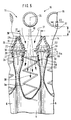
- the sleeves 14 are provided with a compressed-air receiving zone 19, which from a compressed-air receiving opening 20 tapers in the direction of flow TR of the compressed air through the sleeve 14 towards the filter hose 6.
- said sleeve can easily "catch” the streams 18 of compressed air, and the capacity of said streams or flows 18 to "co-eject" the air 21 from the clean-gas zone 11 and into the sleeve 14 (see fig. 6) is improved.
- This sleeve 14 also includes a compressed-air constriction zone 22 with a substantially smaller through-flow area than the compressed-air receiving opening 20 and which is positioned between the compressed-air receiving zone 19 and a compressed-air discharge opening 23, through which the compressed air flows from the sleeve 14 to the filter hose 6.
- the speed of the flow 18 of compressed air is increased, whereby the filter hose 6 is subjected to an effective, blow-like expansion along its entire length.
- the sleeve 14 is preferably circular and the diameter D1 of the compressed-air receiving opening 20 is preferably at least 60 % larger, preferably twice the diameter D2 of the narrowest portion of the compressed-air constriction zone 22.
- the compressed-air receiving opening 20 of the sleeve 14 illustrated in fig. 5 has a diameter D1 of 32 mm and the diameter D2 of the smallest portion of the compressed-air constriction zone 22 is 16 mm.
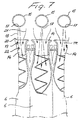
- the sleeve 14 shown in fig. 7 has a diameter D1 of 32 mm and a diameter D2 of 20 mm.
- the diameter D1 of the compressed-air receiving opening 20 is preferably 6-10 times larger, preferably 8 times larger than the diameter D3 of the compressed-air nozzle 17.
- the compressed-air nozzle 17 has a diameter of 4 mm and the sleeves, as stated above, a diameter D1 of the compressed-air receiving opening 20 of 32 mm.
- the distance A between the compressed-air receiving opening 20 and the compressed-air nozzle 17 is preferably substantially smaller than the diameter D1 of the compressed-air receiving opening 20.
- the distance A at the embodiment of fig. 5 is 14 mm and at the embodiment of fig. 7, the distance is 22 mm.
- the length of the tapering compressed-air receiving zone of the sleeve 14 is preferably at least 25 % of the total length of the through-flow zones of the sleeve 14.
- the sleeve 14 illustrated in fig. 5 preferably includes a compressed-air discharge zone 24, which diverges, seen in the direction of flow TR of the compressed air, towards the compressed-air discharge opening 23.
- the compressed-air receiving zone 19 seen from the centre line CL of the sleeve 14
- the compressed-air constriction zone 22 seen from the centre line CL of the sleeve 14
- the compressed-air discharge zone 24 has, seen from the centre line CL of the sleeve 14, convexly curved wall portions 27 which without interruptions connect to the wall portions 26.
- the compressed-air discharge opening 23 preferably has a diameter D4 which is at least 30 % larger than the smallest diameter D2 of the compressed-air constriction zone 22, but smaller than the diameter D1 of the compressed-air receiving opening 20.
- the sleeve 14 attains an "egg-cup like shape" which thereby provides extensive advantages with regard to the flow 18 of compressed air.
- said hose 6 engages and/or is connected to the end portion 14a of the sleeve 14.
- the filter hose 6 preferably includes a portion 6b which surrounds and engages the end portion 14a of the sleeve 14.
- the filter hose 6 preferably extends along the sleeve and its end portion 14a.
- the portion 6d of the filter hose 6 provided closest to the end portion 14a of the sleeve 14, diverges in a direction from said end portion 14a, and if the compressed-air discharge zone diverges, said portion 6d diverges as an extension of this zone 24.
- the portion 6a thereby preferably connects to the end portion 14a without sharp interruptions.
- the portions of the sleeve defining the compressed-air constriction zone 22 have anchoring portions 29 through which the sleeve 14 and the filter hose 6 are secured to the anchoring portions 5.
- These anchoring portions 29 are provided with an annular groove 30 and the fastening is carried out such that the sleeve 14 is pressed into the aperture 12 within the end portions 13 of the filter hose 6. Since the sleeve 14 is elastic, it is hereby somewhat compressed until the groove 30 is in a position just opposite to the anchoring portions 5. Hereby, the sleeve 14 springs outwardly and clamp the end portions 13 of the filter hose 6 between said sleeve and the anchoring portions 5.
- the portions of the sleeve defining the compressed-air receiving zone 19 are disposed on the clean-gas side of the anchoring portions 5, i.e. said portions are positioned in the clean-gas zone 11, which is advantageous since there is room therein for expanded portions of the sleeve 14.
- the sleeve 14 illustrated in fig. 7 has a more simple design, but still fulfils the requirements set.
- the compressed-air constriction zone 22 thereof is cylindrical and extends from the compressed-air receiving zone 19 to the compressed-air discharge opening 23.
- the sleeves described provide an advantageous flow of compressed air and co-ejection of air from the clean-gas zone 11, they also enable a turbulence-free discharge of clean gas from the filter hose 6 to the clean-gas zone 11, which is also important.
- the sleeve may have other dimensions than described, it is preferably circular but may have another shape, it may be made of plastic or another suitable material and it can be mounted in other ways than described.
- the filter device has only one filter hose, but normally it includes several filter cassettes with a larger number of filter hoses and associated sleeves 14. If an end portion of the helical separating thread is provided to surround the end portion 14a, then the filter hose 6 engages and/or surrounds also this end portion.
Landscapes
- Chemical & Material Sciences (AREA)
- Chemical Kinetics & Catalysis (AREA)
- Physics & Mathematics (AREA)
- Geometry (AREA)
- Filtering Of Dispersed Particles In Gases (AREA)
- Electrical Discharge Machining, Electrochemical Machining, And Combined Machining (AREA)
- Control Of Motors That Do Not Use Commutators (AREA)
- Details Of Connecting Devices For Male And Female Coupling (AREA)
- Surgical Instruments (AREA)
- Sink And Installation For Waste Water (AREA)
Applications Claiming Priority (2)
| Application Number | Priority Date | Filing Date | Title |
|---|---|---|---|
| SE8901704 | 1989-05-12 | ||
| SE8901704A SE465912B (sv) | 1989-05-12 | 1989-05-12 | Anordning vid en filterslang som ingaar i ett slangfilter |
Publications (2)
| Publication Number | Publication Date |
|---|---|
| EP0399249A1 EP0399249A1 (en) | 1990-11-28 |
| EP0399249B1 true EP0399249B1 (en) | 1994-08-03 |
Family
ID=20375934
Family Applications (1)
| Application Number | Title | Priority Date | Filing Date |
|---|---|---|---|
| EP90108235A Expired - Lifetime EP0399249B1 (en) | 1989-05-12 | 1990-04-30 | Device at a filter hose |
Country Status (6)
| Country | Link |
|---|---|
| US (1) | US5062873A (da) |
| EP (1) | EP0399249B1 (da) |
| AT (1) | ATE109369T1 (da) |
| DE (1) | DE69011204T2 (da) |
| DK (1) | DK0399249T3 (da) |
| SE (1) | SE465912B (da) |
Families Citing this family (18)
| Publication number | Priority date | Publication date | Assignee | Title |
|---|---|---|---|---|
| US5393327A (en) * | 1993-04-27 | 1995-02-28 | Thermo-Kinetics Industries, Inc. | Cartridge filter and method |
| US5421845A (en) * | 1993-09-16 | 1995-06-06 | Hosokawa Micron International Inc. | Low pressure pulse jet dust collector |
| DE69524076T2 (de) * | 1994-04-11 | 2002-07-11 | Donaldson Co., Inc. | Luftfilteranordnung zum filtrieren von luft mit teilchen |
| DE19714337A1 (de) * | 1997-04-08 | 1998-10-15 | Graf Epe Gmbh | Abgasreinigung und Verfahren zum Betreiben einer solchen Abgasreinigung |
| US6090173A (en) * | 1998-08-07 | 2000-07-18 | Donaldson Company, Inc. | Air filter assembly for filtering air with particulate matter |
| RU2276618C1 (ru) * | 2005-01-31 | 2006-05-20 | Государственное образовательное учреждение высшего профессионального образования Воронежская государственная технологическая академия | Фильтр с импульсной регенерацией |
| RU2283166C1 (ru) * | 2005-03-28 | 2006-09-10 | ЗАО "Кондор-Эко" | Рукавный фильтр |
| US7309366B2 (en) * | 2005-04-05 | 2007-12-18 | Jensen Robert M | Bag cleaning compressed air nozzle |
| US8075674B2 (en) | 2006-11-30 | 2011-12-13 | Donaldson Company, Inc. | Filter apparatus with pulse cleaning and methods for pulse cleaning filters |
| WO2008067448A2 (en) | 2006-11-30 | 2008-06-05 | Donaldson Company, Inc. | Nozzle arrangements and method for cleaning filter elements |
| WO2008067453A2 (en) | 2006-11-30 | 2008-06-05 | Donaldson Company, Inc. | System configuration of pulsed cleaned panel-style filter elements and methods |
| US8057563B2 (en) | 2006-11-30 | 2011-11-15 | Donaldson Company, Inc. | Filter apparatus configuration of pulsed cleaned panel-style filters and methods |
| WO2009102381A1 (en) * | 2008-02-14 | 2009-08-20 | Donaldson Company, Inc. | Method for selecting a filter element for a dust collector with regeneration with pulsed gas |
| US7918908B2 (en) * | 2008-04-30 | 2011-04-05 | Venturedyne, Ltd. | Dust collector with equalized cleaning performance |
| US8118900B2 (en) | 2009-09-30 | 2012-02-21 | Donaldson Company, Inc. | Dust collector and methods |
| CN104353299A (zh) * | 2014-11-19 | 2015-02-18 | 张家港市艾尔环保设备有限公司 | 高负压型除尘器 |
| RU2698672C1 (ru) * | 2018-10-01 | 2019-08-28 | Артем Сергеевич Ткаченко | Фильтр для очистки газов |
| GB2592267A (en) * | 2020-02-24 | 2021-08-25 | Altair Uk Ltd | Pulse nozzle for filter cleaning systems |
Family Cites Families (22)
| Publication number | Priority date | Publication date | Assignee | Title |
|---|---|---|---|---|
| US3377783A (en) * | 1965-08-30 | 1968-04-16 | Henry T. Young | Filter collector |
| NO130566C (da) * | 1971-07-14 | 1975-01-08 | Ardal Og Sunndal Verk | |
| US3798878A (en) * | 1972-08-18 | 1974-03-26 | Gen Resource Corp | Filter cleaning apparatus |
| US3876402A (en) * | 1972-09-28 | 1975-04-08 | Standard Havens | Apparatus for separating particulate matter from a gas stream |
| CH545645A (da) * | 1972-12-07 | 1974-02-15 | ||
| US4105421A (en) * | 1976-05-28 | 1978-08-08 | Standard Havens, Inc. | Disposable filter cartridge |
| IN155824B (da) * | 1976-06-28 | 1985-03-16 | Ashland Oil Inc | |
| DE7708188U1 (de) * | 1977-03-17 | 1977-06-30 | Uop-Kavag, 6467 Hasselroth | Schraubhalter fuer filterschlauch |
| US4220459A (en) * | 1978-10-16 | 1980-09-02 | Wheelabrator-Frye Inc. | Filter device with top access to filter bag |
| US4251244A (en) * | 1979-03-12 | 1981-02-17 | Wheelabrator-Frye Inc. | Jet pulse bag type collector |
| GB2050199B (en) * | 1979-05-21 | 1983-09-01 | American Air Filter Co | Filter bag-mounting arrangement |
| US4272263A (en) * | 1979-05-21 | 1981-06-09 | American Air Filter Company, Inc. | Filter arrangement |
| US4278454A (en) * | 1979-05-29 | 1981-07-14 | Wehr Corporation | Filter apparatus with reverse flow cleaning |
| US4266954A (en) * | 1979-07-12 | 1981-05-12 | The Air Preheater Company, Inc. | Holder for bag filter |
| US4276069A (en) * | 1979-09-12 | 1981-06-30 | American Air Filter Company, Inc. | Filter arrangement |
| US4256473A (en) * | 1979-10-05 | 1981-03-17 | The Spencer Turbine Company | Filter bag attaching means |
| US4253856A (en) * | 1979-11-09 | 1981-03-03 | American Air Filter Company, Inc. | Filter arrangement |
| US4300927A (en) * | 1980-10-31 | 1981-11-17 | American Air Filter Company, Inc. | Pocket filter arrangement |
| US4312648A (en) * | 1980-12-08 | 1982-01-26 | American Air Filter Company, Inc. | Pocket filter arrangement |
| DE3412000A1 (de) * | 1984-03-31 | 1985-10-10 | Dr. Madaus & Co, 5000 Köln | Pneumatische mischvorrichtung fuer schuettgueter |
| US4648889A (en) * | 1985-05-03 | 1987-03-10 | Jensen Robert M | Top inlet baghouse construction |
| FR2625916B1 (fr) * | 1988-01-15 | 1990-06-29 | Aaf Sa | Dispositif d'accrochage de manches filtrantes dans un appareil de depoussierage |
-
1989
- 1989-05-12 SE SE8901704A patent/SE465912B/sv not_active IP Right Cessation
-
1990
- 1990-04-30 EP EP90108235A patent/EP0399249B1/en not_active Expired - Lifetime
- 1990-04-30 DK DK90108235.4T patent/DK0399249T3/da active
- 1990-04-30 DE DE69011204T patent/DE69011204T2/de not_active Expired - Fee Related
- 1990-04-30 AT AT90108235T patent/ATE109369T1/de not_active IP Right Cessation
- 1990-05-07 US US07/520,049 patent/US5062873A/en not_active Expired - Lifetime
Also Published As
| Publication number | Publication date |
|---|---|
| ATE109369T1 (de) | 1994-08-15 |
| SE8901704D0 (sv) | 1989-05-12 |
| US5062873A (en) | 1991-11-05 |
| SE465912B (sv) | 1991-11-18 |
| EP0399249A1 (en) | 1990-11-28 |
| DE69011204D1 (de) | 1994-09-08 |
| DK0399249T3 (da) | 1994-10-24 |
| DE69011204T2 (de) | 1995-03-30 |
| SE8901704L (sv) | 1990-11-13 |
Similar Documents
| Publication | Publication Date | Title |
|---|---|---|
| EP0399249B1 (en) | Device at a filter hose | |
| US4445915A (en) | Dust collector filter cartridge and attachment means for suspending same from baghouse tube sheet | |
| EP0773823B1 (en) | A flow control member for a filter cartridge cleaning system | |
| US4276069A (en) | Filter arrangement | |
| AU2008269870B2 (en) | Filter bag for use in dust collector | |
| CA1136070A (en) | Filter arrangement | |
| US4424070A (en) | Dust collecting filter cartridge and attachment structure for suspending same from baghouse tube sheet | |
| US4578092A (en) | Method and apparatus for improving the operation of a dust collector | |
| EP0605245B1 (en) | Powder conveying apparatus | |
| CA1148874A (en) | Filter arrangement | |
| US4666472A (en) | Dust collector with deflector means | |
| KR20000005295A (ko) | 공기로부터 미세한 분진을 제거하는 분리기 | |
| US4247313A (en) | Gas-particulate separator with pulse-jet cleanable filter elements | |
| US5383973A (en) | Method for cleaning heating, ventilating and air conditioning ducts | |
| US3509911A (en) | Dust collecting plenum installation | |
| KR20040049865A (ko) | 꽃가루의 불순물 제거방법 및 그 장치 | |
| US3951630A (en) | Tapered tubular filter element having flared outlet | |
| EP0900120B1 (en) | Cleaning device for filter of dust filter device | |
| US4662910A (en) | Device for removing particulates from a gas stream | |
| CN214513337U (zh) | 一种布袋除尘器清灰装置 | |
| RU2048207C1 (ru) | Циклон а.с.карпенко | |
| CN216367070U (zh) | 一种脉冲布袋除尘器引射器装置 | |
| CN209809783U (zh) | 真空环境下的粉尘输出系统 | |
| SU1678421A2 (ru) | Самоочищающийс рукавный фильтр | |
| SU1064986A1 (ru) | Пылеуловитель инерционный |
Legal Events
| Date | Code | Title | Description |
|---|---|---|---|
| PUAI | Public reference made under article 153(3) epc to a published international application that has entered the european phase |
Free format text: ORIGINAL CODE: 0009012 |
|
| AK | Designated contracting states |
Kind code of ref document: A1 Designated state(s): AT BE CH DE DK ES FR GB GR IT LI LU NL SE |
|
| 17P | Request for examination filed |
Effective date: 19910513 |
|
| RAP1 | Party data changed (applicant data changed or rights of an application transferred) |
Owner name: LICENCIA HOLDING S.A. |
|
| 17Q | First examination report despatched |
Effective date: 19920902 |
|
| RAP1 | Party data changed (applicant data changed or rights of an application transferred) |
Owner name: NORDFAB A/S |
|
| GRAA | (expected) grant |
Free format text: ORIGINAL CODE: 0009210 |
|
| AK | Designated contracting states |
Kind code of ref document: B1 Designated state(s): AT BE CH DE DK ES FR GB GR IT LI LU NL SE |
|
| PG25 | Lapsed in a contracting state [announced via postgrant information from national office to epo] |
Ref country code: IT Free format text: LAPSE BECAUSE OF FAILURE TO SUBMIT A TRANSLATION OF THE DESCRIPTION OR TO PAY THE FEE WITHIN THE PRESCRIBED TIME-LIMIT;WARNING: LAPSES OF ITALIAN PATENTS WITH EFFECTIVE DATE BEFORE 2007 MAY HAVE OCCURRED AT ANY TIME BEFORE 2007. THE CORRECT EFFECTIVE DATE MAY BE DIFFERENT FROM THE ONE RECORDED. Effective date: 19940803 Ref country code: GR Free format text: LAPSE BECAUSE OF FAILURE TO SUBMIT A TRANSLATION OF THE DESCRIPTION OR TO PAY THE FEE WITHIN THE PRESCRIBED TIME-LIMIT Effective date: 19940803 Ref country code: NL Effective date: 19940803 Ref country code: BE Effective date: 19940803 Ref country code: ES Free format text: THE PATENT HAS BEEN ANNULLED BY A DECISION OF A NATIONAL AUTHORITY Effective date: 19940803 Ref country code: CH Effective date: 19940803 Ref country code: FR Effective date: 19940803 Ref country code: AT Effective date: 19940803 Ref country code: LI Effective date: 19940803 |
|
| REF | Corresponds to: |
Ref document number: 109369 Country of ref document: AT Date of ref document: 19940815 Kind code of ref document: T |
|
| REF | Corresponds to: |
Ref document number: 69011204 Country of ref document: DE Date of ref document: 19940908 |
|
| REG | Reference to a national code |
Ref country code: DK Ref legal event code: T3 |
|
| PG25 | Lapsed in a contracting state [announced via postgrant information from national office to epo] |
Ref country code: SE Effective date: 19941103 |
|
| REG | Reference to a national code |
Ref country code: CH Ref legal event code: PL |
|
| EN | Fr: translation not filed | ||
| NLV1 | Nl: lapsed or annulled due to failure to fulfill the requirements of art. 29p and 29m of the patents act | ||
| PG25 | Lapsed in a contracting state [announced via postgrant information from national office to epo] |
Ref country code: LU Free format text: LAPSE BECAUSE OF NON-PAYMENT OF DUE FEES Effective date: 19950430 |
|
| PLBE | No opposition filed within time limit |
Free format text: ORIGINAL CODE: 0009261 |
|
| 26N | No opposition filed | ||
| REG | Reference to a national code |
Ref country code: GB Ref legal event code: IF02 |
|
| PGFP | Annual fee paid to national office [announced via postgrant information from national office to epo] |
Ref country code: GB Payment date: 20030425 Year of fee payment: 14 |
|
| PGFP | Annual fee paid to national office [announced via postgrant information from national office to epo] |
Ref country code: DE Payment date: 20030627 Year of fee payment: 14 |
|
| PG25 | Lapsed in a contracting state [announced via postgrant information from national office to epo] |
Ref country code: GB Free format text: LAPSE BECAUSE OF NON-PAYMENT OF DUE FEES Effective date: 20040430 |
|
| PG25 | Lapsed in a contracting state [announced via postgrant information from national office to epo] |
Ref country code: DE Free format text: LAPSE BECAUSE OF NON-PAYMENT OF DUE FEES Effective date: 20041103 |
|
| GBPC | Gb: european patent ceased through non-payment of renewal fee |
Effective date: 20040430 |
|
| PGFP | Annual fee paid to national office [announced via postgrant information from national office to epo] |
Ref country code: DK Payment date: 20090424 Year of fee payment: 20 |
|
| REG | Reference to a national code |
Ref country code: DK Ref legal event code: EUP |