EP0398796B1 - Interféromètre en anneau - Google Patents
Interféromètre en anneau Download PDFInfo
- Publication number
- EP0398796B1 EP0398796B1 EP90401279A EP90401279A EP0398796B1 EP 0398796 B1 EP0398796 B1 EP 0398796B1 EP 90401279 A EP90401279 A EP 90401279A EP 90401279 A EP90401279 A EP 90401279A EP 0398796 B1 EP0398796 B1 EP 0398796B1
- Authority
- EP
- European Patent Office
- Prior art keywords
- fibre
- interferometer
- fiber
- detector
- optical fibre
- Prior art date
- Legal status (The legal status is an assumption and is not a legal conclusion. Google has not performed a legal analysis and makes no representation as to the accuracy of the status listed.)
- Expired - Lifetime
Links
- 239000000835 fiber Substances 0.000 claims description 33
- 239000013307 optical fiber Substances 0.000 claims description 19
- 238000005259 measurement Methods 0.000 claims description 9
- 230000005693 optoelectronics Effects 0.000 claims description 9
- 239000000463 material Substances 0.000 claims description 3
- 238000004321 preservation Methods 0.000 claims 1
- 230000003287 optical effect Effects 0.000 description 8
- 230000010287 polarization Effects 0.000 description 8
- 230000000694 effects Effects 0.000 description 6
- 230000004907 flux Effects 0.000 description 6
- 230000008878 coupling Effects 0.000 description 4
- 238000010168 coupling process Methods 0.000 description 4
- 238000005859 coupling reaction Methods 0.000 description 4
- 238000010586 diagram Methods 0.000 description 3
- 230000010363 phase shift Effects 0.000 description 3
- VYPSYNLAJGMNEJ-UHFFFAOYSA-N Silicium dioxide Chemical compound O=[Si]=O VYPSYNLAJGMNEJ-UHFFFAOYSA-N 0.000 description 2
- 230000033228 biological regulation Effects 0.000 description 2
- 206010001488 Aggression Diseases 0.000 description 1
- 239000000853 adhesive Substances 0.000 description 1
- 238000004026 adhesive bonding Methods 0.000 description 1
- 230000001070 adhesive effect Effects 0.000 description 1
- 230000016571 aggressive behavior Effects 0.000 description 1
- 230000003321 amplification Effects 0.000 description 1
- 238000001514 detection method Methods 0.000 description 1
- 230000005670 electromagnetic radiation Effects 0.000 description 1
- 230000007613 environmental effect Effects 0.000 description 1
- 230000003628 erosive effect Effects 0.000 description 1
- 238000001914 filtration Methods 0.000 description 1
- 238000002955 isolation Methods 0.000 description 1
- 238000000034 method Methods 0.000 description 1
- 238000003199 nucleic acid amplification method Methods 0.000 description 1
- 244000045947 parasite Species 0.000 description 1
- 230000003071 parasitic effect Effects 0.000 description 1
- 238000005498 polishing Methods 0.000 description 1
- 230000005855 radiation Effects 0.000 description 1
- 230000035945 sensitivity Effects 0.000 description 1
- 239000000377 silicon dioxide Substances 0.000 description 1
- 239000012780 transparent material Substances 0.000 description 1
Images

Classifications
-
- G—PHYSICS
- G01—MEASURING; TESTING
- G01C—MEASURING DISTANCES, LEVELS OR BEARINGS; SURVEYING; NAVIGATION; GYROSCOPIC INSTRUMENTS; PHOTOGRAMMETRY OR VIDEOGRAMMETRY
- G01C19/00—Gyroscopes; Turn-sensitive devices using vibrating masses; Turn-sensitive devices without moving masses; Measuring angular rate using gyroscopic effects
- G01C19/58—Turn-sensitive devices without moving masses
- G01C19/64—Gyrometers using the Sagnac effect, i.e. rotation-induced shifts between counter-rotating electromagnetic beams
- G01C19/72—Gyrometers using the Sagnac effect, i.e. rotation-induced shifts between counter-rotating electromagnetic beams with counter-rotating light beams in a passive ring, e.g. fibre laser gyrometers
- G01C19/721—Details, e.g. optical or electronical details
Definitions
- the present invention relates to a ring interferometer.
- Gyrometers with reciprocal minimum configuration are known. Particularly simple, this configuration includes a separator device, with three single-mode doors, necessary to inject the incident light at the ends of a loop of optical fiber constituting the sensitive part of the interferometer.
- the single input-output section of the separator constitutes a unimodal filter which ensures perfect optical reciprocity of the system.
- the separator is multifunctional: it ensures the mode filtering by polarization of the light, and the modulation of the counter-rotating waves to allow the processing of the detected signal.
- the system further includes a light source and an optoelectronic detection device.
- the various aforementioned elements are grouped in a single housing of reduced size and connected to the electronic control device by a power cable and a cable for transporting information from the detector.
- the present invention relates to an interferometer of the ring type with a remote processing and supply unit, this interferometer being as compact as possible and presenting practically no risk of being disturbed by electromagnetic parasites.
- the interferometer according to the invention is a ring interferometer with remote processing and supply unit, the optoelectronic detector of which is placed at a distance from the compact measuring head and connected by the latter by an optical fiber and comprising a shunt between the light source and the measuring head, characterized in that the shunt comprises a curved single-mode fiber eroded locally and surface, the eroded area being polished, a block of material transparent to the wavelengths used with asymmetrical geometry, and the refractive index of which is higher than that of the fiber, being glued against the polished face of the fiber, said optical fiber connecting the optoelectronic detector to the measuring head being glued against a face of said block.
- the light source is also placed at a distance from the measurement head and connected to the latter by an optical fiber.
- a ring type interferometric system comprises, as shown in FIG. 1, a light source 1 connected to a fiber optic ring 2 via a tap-off 3 and a separator or input-output port 4.
- a detector 5 is also connected to the derivative 3.
- the diverter 3 makes it possible to detect the useful light flux returning from the ring 2, constituting the sensitive part of the interferometer, by taking a part of the light flux containing the phase shift information and direct it to the detector 5.
- the section 6 downstream of the differentiator 3 is rigorously single-mode (in the spatial sense and in the sense of polarization), namely the section comprising the single-mode optical fibers 2 and 7 (fiber 7 between differentiator 3 and separator 4 ) single-mode.
- the tap 3 requires only two single-mode gates for the link by single mode optical fiber 8 with the source 1, and the input-output link with the fiber 7.
- the link 9 between the tap 3 and the detector 5 can also well be multimode than singlemode.
- the diverter 3 ( Figure 2) is for example made using a single-mode fiber 10 kept curved by gluing in a suitable support 11. After local surface erosion of this fiber and polishing of the face 12 thus obtained, a block 13 of transparent material is bonded to this face with the wavelengths used and whose refractive index is higher than that of the fiber. Thus, part of the useful light flux (coming from the ring 2) transported by the fiber can be coupled to the outside. This flow propagates in block 13 and is directed to an opto-electronic detector 14 after reflection and focusing.
- the asymmetric geometry of the block 13 makes it possible to refract outside the field of the detector and outside the block (rays R ′) the part of the flow sampled in the source-interferometer direction.
- the multimode nature of the propagation of light waves between the differentiator 3 and the detector 5 does not disturb the operation of the interferometric system, which remains generally reciprocal.
- the connection between the detector 14 and the remote central unit 15 for processing the detector signals and for supplying power is carried out by shielded electrical cable, this cable, often relatively long, being able to be parasitized by electromagnetic disturbances, as specified above.
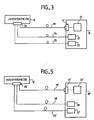
- the interferometer head 16 no longer includes an optoelectronic detector, and the latter (17) is deported to the remote processing center 18.
- the connection between the head 16 and the detector 17 is provided by an optical link to fiber 19.
- This fiber 19 can be multimode as well as monomode. Preferably, it is multimode, because in this case it only requires simple connectors which are easy to implement.
- the control unit 18 essentially comprises an electronic device 20 for processing the signals from the detector 17, a device 21 for producing modulation and feedback signals for the phase modulator of the head 16, and a device 22 for supplying light source energy, regulation and control. All these elements being well known, will not be described in more detail.
- the connection between the elements 21 and 22 and the head 16 is carried out by shielded electric cables 24.25 respectively.
- the cables 19, 24, 25 are connected to the head 16 by suitable connectors 26.
- the diverter 27 (FIG. 4) is produced from a single mode optical fiber 28 kept curved in a support 29.
- the fiber 28 is locally and surface eroded at 30, then polished.
- a block 31 of material with a refractive index greater than that of the fiber 28 is glued against this polished face.
- the geometry of the block 31 is such that the fraction 32 of useful light flux taken from the fiber 28 is refracted along one face of this block.
- the block 31 has a prismatic shape.
- the fiber 33 has a large guide core and is polished at its end and brought into contact with the block 31.
- the axis 36 of symmetry (axial) of the fiber 33 is aligned along the mean direction of the beam 32 to optimize the coupling of light energy (neglecting the angle of refraction of the beam 32 when it passes from the block 31 into the fiber 33).
- an adhesive polymerizable by ultraviolet radiation and with an appropriate refractive index is advantageously used at their interface.
- the leakage angle ⁇ m of the light in the block 31 is of the order of 16 °.
- the diffraction is very small, of the order of 10 ⁇ 3.
- the diffraction angle Alpha is of the order of 10 to 20 °.
- the light energy refracted out of the single-mode fiber 28 in the direction opposite to the useful direction (rays 37) is not coupled in the multimode fiber 33 and does not degrade the signal to noise ratio of l 'interferometer.
- the light flux 32 useful for interferometric measurement by phase shift, and coupled in the fiber 33, is directed by the latter towards the remote detector 17.
- the coupling between the fiber 33 and the detector 17 is carried out in a manner known per se.
- the ring interferometer thus produced essentially consists of the measuring head 16, the control unit 18 and the connections 19, 24, 25, the opto-electronic detector (17) being arranged in the control unit at the closer to the floors amplification (20), which reduces the sensitivity of the system to electromagnetic disturbances.
- the electrical connections between the measuring head and the control unit are reduced to the connections specific to the light source and to the modulation and feedback connections.
- the signal useful for the measurement propagates in optical form, which offers guarantees of isolation from electromagnetic radiation, and limits parasitic interference between electrical connections.
- the connection between the head 16 and the control unit 18 can be carried out with a mixed cable, optical and electrical.
- the light source is offset from the head of kannre, connecting it to the measuring head by a single-mode fiber.
- the measuring head 16 ' is connected to the control unit 18' by an electric cable 24 'and two optical fibers 19' and 38.
- the cable 24 ' makes it possible to apply the modulation and the feedback signals to the phase modulator (not shown) of the measuring head.
- the multimode fiber 19 ' provides the optical link between the interferometer and the detector 17' of the unit 18 '.
- the fiber 38 a single mode with linear polarization conservation, provides the optical link between the source 39 (arranged in the unit 18 ') and the interferometer 16'.
- the 18 'unit also includes circuits 20 'for processing the signal supplied by the detector 17'.
- the device of FIG. 5 is advantageous in that the detector 17 'is as close as possible to the circuits 20' which process its signal, and in that the light source 39 is also very close to its power and regulation devices . In most applications, it is necessary to regulate the temperature of the light source, which is much easier to implement in the unit 18 ′, which can be far enough from the measurement site, and therefore easily protected from environmental aggressions, while the measuring head 16 ′ risks being subjected to significant temperature variations.
Landscapes
- Physics & Mathematics (AREA)
- Engineering & Computer Science (AREA)
- Optics & Photonics (AREA)
- Electromagnetism (AREA)
- Power Engineering (AREA)
- General Physics & Mathematics (AREA)
- Radar, Positioning & Navigation (AREA)
- Remote Sensing (AREA)
- Instruments For Measurement Of Length By Optical Means (AREA)
- Gyroscopes (AREA)
Description
- La présente invention se rapporte à un interféromètre en anneau.
- Dans certains systèmes interférométriques, tels que des gyromètres, l'utilisation d'une configuration particulière, dite "réciproque minimale", permet d'annuler exactement tout déphasage autre que ceux induits par des effets non réciproques. Ces effets non réciproques sont en particulier l'effet Faraday (effet magnéto-optique colinéaire) et l'effet Sagnac, selon lequel, par effet inertiel relativiste, la rotation de l'interféromètre par rapport à un repère galiléen détruit la symétrie des temps de propagation.
- On connaît des gyromètres à configuration minimale réciproque. Particulièrement simple, cette configuration comporte un dispositif séparateur, à trois portes monomodes, nécessaire pour injecter la lumière incidente aux extrémités d'une boucle de fibre optique constituant la partie sensible de l'interféromètre.
- La section unique d'entrée-sortie du séparateur constitue un filtre unimodal qui assure la parfaite réciprocité optique du système. Suivant un mode de réalisation, le séparateur est multifonction : il assure le filtrage de mode par polarisation de la lumière, et la modulation des ondes contrarotatives pour permettre le traitement du signal détecté. Le système comporte en outre une source lumineuse et un dispositif optoélectronique de détection. Suivant un mode de réalisation préféré de ce dispositif connu, les divers éléments précités sont regroupés dans un boîtier unique de taille réduite et relié au dispositif électronique de contrôle par un câble d'alimentation et un câble de transport des informations en provenance du détecteur.
- Ces câbles électriques, même lorsqu'ils sont bien blindés, sont sujets au parasitage électromagnétique, ce qui perturbe les mesures des signaux détectés.
- On connaît d'après le document US-A-4 153 370 un transducteur microinterférométrique dans lequel la liaison entre le capteur et les détecteurs se fait par fibres optiques, mais ce document ne préconise ni ne suggère aucune solution à la liaison directive entre un anneau interférométrique et son détecteur.
- La présente invention a pour objet un interféromètre du type en anneau à centrale de traitement et d'alimentation déportée, cet interféromètre étant le plus compact possible et ne présentant pratiquement aucun risque d'être perturbé par des parasités électromagnétiques.
- L'interféromètre conforme à l'invention est un interféromètre en anneau à centrale de traitement et d'alimentation déportée, dont le détecteur optoélectronique est disposé à distance de la tête de mesure compacte et relié par celle-ci par une fibre optique et comportant un dérivateur entre la source lumineuse et la tête de mesure, caractérisé par le fait que le dérivateur comporte une fibre monomode courbée érodée localement et superficiellement, la zone érodée étant polie, un bloc de matériau transparent aux longueurs d'ondes utilisées à géométrie asymétrique, et dont l'indice de réfraction est supérieur à celui de la fibre, étant collé contre la face polie de la fibre, ladite fibre optique reliant le détecteur optoélectronique à la tête de mesure étant collé contre une face dudit bloc.
- Selon un mode de réalisation de l'invention, la source lumineuse est également disposée à distance de la tête de mesure et reliée à celle-ci par une fibre optique.
- La présente invention sera mieux comprise à la lecture de la description détaillée de plusieurs modes de réalisation et illustrée par le dessin annexé, sur lequel :
- la figure 1 est le schéma simplifié d'un interféromètre en anneau de l'art antérieur,
- la figure 2 est une vue en coupe d'un dérivateur de lumière utilisé dans l'interféromètre de la figure 1,
- la figure 3 est le schéma simplifié d'un interféromètre en anneau conforme à l'invention,
- la figure 4 est une vue en coupe d'un dérivateur de lumière utilisé dans l'interféromètre de la figure 3, et
- la figure 5 est le schéma simplifié d'une variante d'un interféromètre en anneau conforme à l'invention.
- Un système interférométrique du type en anneau comporte, comme représenté en figure 1, une source lumineuse 1 reliée à un anneau 2 en fibre optique via un dérivateur 3 et un séparateur ou port d'entrée-sortie 4. Un détecteur 5 est également relié au dérivateur 3.
- Le dérivateur 3 permet de détecter le flux lumineux utile qui revient de l'anneau 2, constituant la partie sensible de l'interféromètre, en prélevant une partie du flux lumineux contenant les informations de déphasage et de le diriger vers le détecteur 5.
- La réciprocité du système est obtenue si la section 6 en aval du dérivateur 3 est rigoureusement monomode (au sens spatial et au sens de la polarisation) à savoir la section comportant les fibres optiques monomodes 2 et 7 (fibre 7 entre dérivateur 3 et séparateur 4) monomodes. Ainsi, le dérivateur 3 ne nécessite que deux portes monomodes pour la liaison par fibre optique monomode 8 avec la source 1, et la liaison d'entrée-sortie avec la fibre 7. La liaison 9 entre le dérivateur 3 et le détecteur 5 peut aussi bien être multimode que monomode.
- Le dérivateur 3 (figure 2) est par exemple réalisé à l'aide d'une fibre monomode 10 maintenue courbée par collage dans un support 11 approprié. Après érosion locale superficielle de cette fibre et polissage de la face 12 ainsi obtenue, on colle sur cette face un bloc 13 de matériau transparent aux longueurs d'ondes utilisées et dont l'indice de réfraction est supérieur à celui de la fibre. Ainsi, une partie du flux lumineux utile (venant de l'anneau 2) transporté par la fibre peut être couplé vers l'extérieur. Ce flux se propage dans le bloc 13 et est dirigé sur un détecteur opto-électronique 14 après réflexion et focalisation. La géométrie asymétrique du bloc 13 permet de réfracter hors du champ du détecteur et hors du bloc (rayons R') la partie de flux prélevé dans le sens source-interféromètre. La nature multimode de la propagation des ondes lumineuses entre le dérivateur 3 et le détecteur 5 ne perturbe pas le fonctionnement du système interférométrique, qui reste globalement réciproque.
- La liaison entre le détecteur 14 et la centrale distante 15 de traitement des signaux du détecteur et d'alimentation est réalisée en câble électrique blindé, ce câble, souvent relativement long, pouvant être parasité par des perturbations électromagnétiques, comme précisé ci-dessus.
- Le système interférométrique conforme à l'invention et schématisé en figure 3 ne présente pas ces risques de parasitage. En effet, la tête d'interféromètre 16 ne comporte plus de détecteur optoélectronique, et celui-ci (17) est déporté dans la centrale distante de traitement 18. La liaison entre la tête 16 et le détecteur 17 est assurée par une liaison optique à fibre 19. Cette fibre 19 peut aussi bien être multimode que monomode. De préférence, elle est multimode, car dans ce cas elle ne nécessite que des connecteurs simples et faciles à mettre en oeuvre.
- La centrale 18 comporte essentiellement un dispositif électronique 20 de traitement des signaux issus du détecteur 17, un dispositif 21 de production de signaux de modulation et de contre-réaction pour le modulateur de phase de la tête 16, et un dispositif 22 d'alimentation en énergie de la source lumineuse, de régulation et de contrôle. Tous ces éléments étant bien connus, ne seront pas décrits plus en détail. La liaison entre les éléments 21 et 22 et la tête 16 est réalisée par des câbles électriques blindés 24,25 respectivement. Les câbles 19,24,25 sont reliés à la tête 16 par des connecteurs 26 appropriés.
- Le dérivateur 27 (figure 4) est réalisé à partir d'une fibre optique monomode 28 maintenue courbée dans un support 29. La fibre 28 est érodée localement et superficiellement en 30, puis polie. Un bloc 31 en matériau d'indice de réfraction supérieur à celui de la fibre 28 est collé contre cette face polie. La géométrie du bloc 31 est telle que la fraction 32 de flux lumineux utile prélevé de la fibre 28 soit réfractée suivant une face de ce bloc. Dans le mode de réalisation représenté, le bloc 31 a une forme prismatique.
- Une fibre optique multimode 33 maintenue par un manchon de fixation 34, solidement fixé au support 29, est mise en place en contact avec la face 35 du bloc 31 qui reçoit le faisceau utile réfracté 32. La fibre 33 est à large coeur de guidage et est polie à son extrémité et mise en contact avec le bloc 31. L'axe 36 de symétrie (axiale) de la fibre 33 est aligné suivant la direction moyenne du faisceau 32 pour optimiser le couplage d'énergie lumineuse (en négligeant l'angle de réfraction du faisceau 32 lorsqu'il passe du bloc 31 dans la fibre 33). Pour assurer un bon couplage optique entre le bloc 31 et la fibre 33, on utilise avantageusement à leur interface une colle polymérisable en rayonnement ultra-violet et d'indice de réfraction approprié.
- Selon un mode de réalisation, on utilise des fibres optiques à base de silice dopée dont l'indice de réfraction moyen est n1 = 1,46, le bloc 31 ayant un indice plus élevé n2 = 1,52. Dans ces conditions, suivant les lois de la réfraction, l'angle de fuite ϑm de la lumière dans le bloc 31 (par rapport à la face polie de la fibre 28) est de l'ordre de 16°. Dans cette direction, la diffraction est très faible, de l'ordre de 10⁻³. Par contre, dans le plan formant un angle m avec la surface polie, l'angle Alpha de diffraction est de l'ordre de 10 à 20°. Cet angle important (supérieur à 15°) ne s'oppose pas à un couplage efficace dans une fibre optique multimode d'ouverture numérique classique (l'ouverture numérique d'une fibre optique est, par définition, le sinus du demi-angle d'acceptance du faisceau). Dans ce cas, sin ϑm = 0,25.
- Suivant le principe du dérivateur directif, l'énergie lumineuse réfractée hors de la fibre monomode 28 dans le sens opposé au sens utile (rayons 37) n'est pas couplée dans la fibre multimode 33 et ne dégrade pas le rapport signal à bruit de l'interféromètre.
- Le flux lumineux 32 utile à la mesure interférométrique par déphasage, et couplé dans la fibre 33, est dirigé par celle-ci vers le détecteur éloigné 17. Le couplage entre la fibre 33 et le détecteur 17 est réalisé de façon connue en soi.
- L'interféromètre en anneau ainsi réalisé se compose essentiellement de la tête de mesure 16, de l'unité de contrôle 18 et des liaisons 19,24,25, le détecteur opto-électronique (17) étant disposé dans l'unité de contrôle au plus près des étages d'amplification (20), ce qui réduit la sensibilité du système aux perturbations électromagnétiques. Les liaisons électriques entre la tête de mesure et l'unité de contrôle sont réduites aux liaisons propres à la source lumineuse et aux connexions de modulation et de contre-réaction. Le signal utile à la mesure se propage sous forme optique, ce qui offre des garanties d'isolation aux rayonnements électromagnétiques, et limite les interférences parasites entre les liaisons électriques. Bien entendu, la liaison entre la tête 16 et l'unité de contrôle 18 peut être réalisée avec un câble mixte, optique et électrique.
- Selon le mode de réalisation de la figure 5, on déporte la source lumineuse hors de la tête de meusre, en la reliant à la tête de mesure par une fibre monomode.
- En effet, en gyrométrie optique de classe inertielle, le caractère rigoureusement monomode (au sens spatial et au sens de la polarisation) est un critère de première importance. Suivant le degré de précision requis, le contrôle de l'état de polarisation du flux lumineux en provenant de la source nécessite une liaison monomode à conservation de polarisation. Pour cette raison, les connecteurs utilisés sur la liaison monomode entre la source et l'interféromètre doivent conserver la polarisation incidente, ce qui est le cas des connecteurs monomodes connus. Bien entendu, il est alors nécessaire de veiller à bien aligner les axes de polarisation des connecteurs (ou des épissures, le cas échéant).
- Dans le système de la figure 5, la tête de mesure 16' est reliée à l'unité de contrôle 18' par un câble électrique 24' et deux fibres optiques 19' et 38. Le câble 24' permet d'appliquer la modulation et les signaux de contre-réaction au modulateur de phase (non représenté) de la tête de mesure. La fibre 19', multimode, assure la liaison optique entre l'interféromètre et le détecteur 17' de l'unité 18'. La fibre 38, monomode à conservation de polarisation linéaire, assure la liaison optique entre la source 39 (disposée dans l'unité 18') et l'interféromètre 16'. L'unité 18' comporte également des circuits 20' de traitement du signal fourni par le détecteur 17'.
- Le dispositif de la figure 5 est avantageux du fait que le détecteur 17' est le plus près possible des circuits 20' qui traitent son signal, et du fait que la source lumineuse 39 est également très proche de ses dispositifs d'alimentation et de régulation. Dans la plupart des applications, il est nécessaire d'assurer une régulation en température de la source lumineuse, ce qui est beaucoup plus aisé à mettre en oeuvre dans l'unité 18', qui peut être suffisamment éloignée du site de mesure, et donc facilement protégeable des agressions de l'environnement, alors que la tête de mesure 16' risque d'être soumise à des variations de température importantes.
Claims (7)
- Interféromètre en anneau à centrale de traitement et d'alimentation déportée, dont le détecteur optoélectronique (17,17') est disposé à distance de la tête de mesure compacte (16) et relié à celle-ci par une fibre optique (19) et comportant un dérivateur (27) entre la source lumineuse (1) et la tête de mesure (16), caractérisé par le fait que le dérivateur comporte une fibre monomode (28) courbée érodée localement et superficiellement, la zone érodée étant polie (30), un bloc (31) de matériau transparent aux longueurs d'ondes utilisées à géométrie asymétrique, et dont l'indice de réfraction est supérieur à celui de la fibre, étant collé contre la face polie de la fibre, ladite fibre optique (33) reliant le détecteur optoélectronique à la tête de mesure étant collé contre une face (35) dudit bloc.
- Interféromètre selon la revendication 1, caractérisé par le fait que ladite fibre optique reliant le détecteur à la tête de mesure est une fibre multimode.
- Interféromètre selon la revendication 1 ou 2, caractérisé par le fait que le détecteur optoélectronique est disposé dans la centrale de traitement (18, 18').
- Interféromètre selon l'une des revendications précédentes, caractérisé par le fait que la source lumineuse (39) de l'interféromètre est déportée et reliée par une autre fibre optique (38).
- Interféromètre selon la revendication 4, caractérisé par le fait que ladite autre fibre optique est une fibre monomode.
- Interféromètre selon la revendication 5, caractérisé par le fait que ladite autre fibre optique est une fibre monomode à conservation de polarisation linéaire.
- Interféromètre selon la revendication 4 ou 5 ou 6, caractérisé par le fait que la source lumineuse est disposée dans la centrale de traitement (18').
Applications Claiming Priority (2)
| Application Number | Priority Date | Filing Date | Title |
|---|---|---|---|
| FR8906579A FR2647204B1 (fr) | 1989-05-19 | 1989-05-19 | Interferometre en anneau |
| FR8906579 | 1989-05-19 |
Publications (2)
| Publication Number | Publication Date |
|---|---|
| EP0398796A1 EP0398796A1 (fr) | 1990-11-22 |
| EP0398796B1 true EP0398796B1 (fr) | 1993-08-11 |
Family
ID=9381821
Family Applications (1)
| Application Number | Title | Priority Date | Filing Date |
|---|---|---|---|
| EP90401279A Expired - Lifetime EP0398796B1 (fr) | 1989-05-19 | 1990-05-15 | Interféromètre en anneau |
Country Status (7)
| Country | Link |
|---|---|
| US (1) | US5172184A (fr) |
| EP (1) | EP0398796B1 (fr) |
| JP (1) | JP2841863B2 (fr) |
| CA (1) | CA2033184C (fr) |
| DE (1) | DE69002685T2 (fr) |
| FR (1) | FR2647204B1 (fr) |
| WO (1) | WO1990014577A1 (fr) |
Families Citing this family (2)
| Publication number | Priority date | Publication date | Assignee | Title |
|---|---|---|---|---|
| FR2706607B1 (fr) * | 1993-06-15 | 1995-07-21 | Thomson Csf | Capteur de température multipoints reconfigurable. |
| FR2706606B1 (fr) * | 1993-06-15 | 1995-07-21 | Thomson Csf | Capteur à fibre optique reconfigurable. |
Family Cites Families (7)
| Publication number | Priority date | Publication date | Assignee | Title |
|---|---|---|---|---|
| US4153370A (en) * | 1977-12-05 | 1979-05-08 | The United States Of America As Represented By The United States Department Of Energy | Microinterferometer transducer |
| DE2941618A1 (de) * | 1979-10-13 | 1981-04-23 | Licentia Patent-Verwaltungs-Gmbh, 6000 Frankfurt | Verfahren zur messung absoluter drehungen und anordnung zur durchfuehrung des verfahrens |
| DE3044183A1 (de) * | 1980-11-24 | 1982-06-24 | Reinhard Dipl.-Phys. Dr. 7250 Leonberg Ulrich | Verfahren zur optischen messung von laengen und laengenaenderungen und anordnung zur durchfuehrung des verfahrens |
| US4729622A (en) * | 1983-12-05 | 1988-03-08 | Litton Systems, Inc. | Fiber optic polarizer with error signal feedback |
| US4768854A (en) * | 1985-07-11 | 1988-09-06 | Raychem Corp. | Optical fiber distribution network including nondestructive taps and method using same |
| FR2590015B1 (fr) * | 1985-11-08 | 1988-12-09 | Thomson Csf | Dispositif interferometrique en anneau reciproque a fibre optique monomode |
| US4712306A (en) * | 1985-12-27 | 1987-12-15 | Mcdonnell Douglas Corporation | Fiber optic earth rotation gyro compass |
-
1989
- 1989-05-19 FR FR8906579A patent/FR2647204B1/fr not_active Expired - Fee Related
-
1990
- 1990-05-04 CA CA002033184A patent/CA2033184C/fr not_active Expired - Fee Related
- 1990-05-04 WO PCT/FR1990/000320 patent/WO1990014577A1/fr not_active Ceased
- 1990-05-04 JP JP2507398A patent/JP2841863B2/ja not_active Expired - Fee Related
- 1990-05-04 US US07/623,899 patent/US5172184A/en not_active Expired - Lifetime
- 1990-05-15 EP EP90401279A patent/EP0398796B1/fr not_active Expired - Lifetime
- 1990-05-15 DE DE90401279T patent/DE69002685T2/de not_active Expired - Fee Related
Also Published As
| Publication number | Publication date |
|---|---|
| WO1990014577A1 (fr) | 1990-11-29 |
| DE69002685D1 (de) | 1993-09-16 |
| FR2647204A1 (fr) | 1990-11-23 |
| EP0398796A1 (fr) | 1990-11-22 |
| FR2647204B1 (fr) | 1993-12-24 |
| DE69002685T2 (de) | 1993-12-02 |
| CA2033184A1 (fr) | 1990-11-20 |
| US5172184A (en) | 1992-12-15 |
| CA2033184C (fr) | 2001-07-03 |
| JP2841863B2 (ja) | 1998-12-24 |
| JPH03506077A (ja) | 1991-12-26 |
Similar Documents
| Publication | Publication Date | Title |
|---|---|---|
| Wang et al. | Silicon photonics multi-function integrated optical circuit for miniaturized fiber optic gyroscope | |
| US9612177B2 (en) | Ferrule-core concentricity measurement systems and methods | |
| EP0206866B1 (fr) | Dispositif interferometrique en anneau à fibre optique monomode | |
| EP0270429B1 (fr) | Tête de lecture en optique intégrée pour la lecture d'informations enregistrées sur un support magnétique | |
| EP0120737B1 (fr) | Hydrophone à fibre optique | |
| US4188087A (en) | Optical fibre positioning ferrule and connector comprising such a ferrule | |
| EP0266249B1 (fr) | Interferomètre en anneau à fibres optiques à trois axes | |
| EP0081412A2 (fr) | Tête de mesure pour magnétomètre | |
| US5417733A (en) | Alignment system and method for splicing of polarization-maintaining single mode optical fiber | |
| FR2515811A1 (fr) | Dispositif interferometrique de mesure de champ magnetique et capteur de courant electrique comportant un tel dispositif | |
| US7228013B1 (en) | Polymer phase modulator | |
| CN101325453A (zh) | 全光纤光功率监测器 | |
| EP0228315B1 (fr) | Dispositif interferométrique en anneau réciproque à fibre optique monomode | |
| US10416401B2 (en) | In-line uni-directional optical tap detector | |
| EP0018873B1 (fr) | Dispositif compact de couplage optique et gyromètre interferométrique à fibre optique comportant un tel dispositif | |
| FR2661003A2 (fr) | Capteur de champ electrique a effet pockels. | |
| CA2033184C (fr) | Interferometre en anneau | |
| JP5118662B2 (ja) | 光接続器 | |
| EP0448415B1 (fr) | Dispositif de détection à distance d'une grandeur physique, fonctionnant en réflexion | |
| EP0605297A1 (fr) | Appareil de mesure de profil d'indice d'une préforme de fibre optique comportant une enveloppe externe et un coeur | |
| US7239765B1 (en) | Polymer phase modulator | |
| US9115993B1 (en) | Fused PM fiber single-polarization resonator | |
| JP2005292045A (ja) | 光学センサおよび光学センサの組立方法 | |
| JPS61117411A (ja) | 光フアイバセンサ | |
| FR2642165A1 (fr) | Procede de reglage d'un isolateur optique |
Legal Events
| Date | Code | Title | Description |
|---|---|---|---|
| PUAI | Public reference made under article 153(3) epc to a published international application that has entered the european phase |
Free format text: ORIGINAL CODE: 0009012 |
|
| AK | Designated contracting states |
Kind code of ref document: A1 Designated state(s): DE GB IT NL SE |
|
| 17P | Request for examination filed |
Effective date: 19910322 |
|
| 17Q | First examination report despatched |
Effective date: 19920302 |
|
| GRAA | (expected) grant |
Free format text: ORIGINAL CODE: 0009210 |
|
| AK | Designated contracting states |
Kind code of ref document: B1 Designated state(s): DE GB IT NL SE |
|
| ITF | It: translation for a ep patent filed | ||
| REF | Corresponds to: |
Ref document number: 69002685 Country of ref document: DE Date of ref document: 19930916 |
|
| GBT | Gb: translation of ep patent filed (gb section 77(6)(a)/1977) |
Effective date: 19931021 |
|
| RAP2 | Party data changed (patent owner data changed or rights of a patent transferred) |
Owner name: THOMSON-CSF |
|
| NLT2 | Nl: modifications (of names), taken from the european patent patent bulletin |
Owner name: THOMSON-CSF TE PARIJS, FRANKRIJK. |
|
| PLBE | No opposition filed within time limit |
Free format text: ORIGINAL CODE: 0009261 |
|
| STAA | Information on the status of an ep patent application or granted ep patent |
Free format text: STATUS: NO OPPOSITION FILED WITHIN TIME LIMIT |
|
| 26N | No opposition filed | ||
| EAL | Se: european patent in force in sweden |
Ref document number: 90401279.6 |
|
| REG | Reference to a national code |
Ref country code: GB Ref legal event code: IF02 |
|
| PGFP | Annual fee paid to national office [announced via postgrant information from national office to epo] |
Ref country code: NL Payment date: 20040505 Year of fee payment: 15 |
|
| PGFP | Annual fee paid to national office [announced via postgrant information from national office to epo] |
Ref country code: SE Payment date: 20040506 Year of fee payment: 15 |
|
| PGFP | Annual fee paid to national office [announced via postgrant information from national office to epo] |
Ref country code: GB Payment date: 20040512 Year of fee payment: 15 |
|
| PGFP | Annual fee paid to national office [announced via postgrant information from national office to epo] |
Ref country code: DE Payment date: 20040527 Year of fee payment: 15 |
|
| PG25 | Lapsed in a contracting state [announced via postgrant information from national office to epo] |
Ref country code: IT Free format text: LAPSE BECAUSE OF NON-PAYMENT OF DUE FEES;WARNING: LAPSES OF ITALIAN PATENTS WITH EFFECTIVE DATE BEFORE 2007 MAY HAVE OCCURRED AT ANY TIME BEFORE 2007. THE CORRECT EFFECTIVE DATE MAY BE DIFFERENT FROM THE ONE RECORDED. Effective date: 20050515 Ref country code: GB Free format text: LAPSE BECAUSE OF NON-PAYMENT OF DUE FEES Effective date: 20050515 |
|
| PG25 | Lapsed in a contracting state [announced via postgrant information from national office to epo] |
Ref country code: SE Free format text: LAPSE BECAUSE OF NON-PAYMENT OF DUE FEES Effective date: 20050516 |
|
| PG25 | Lapsed in a contracting state [announced via postgrant information from national office to epo] |
Ref country code: NL Free format text: LAPSE BECAUSE OF NON-PAYMENT OF DUE FEES Effective date: 20051201 Ref country code: DE Free format text: LAPSE BECAUSE OF NON-PAYMENT OF DUE FEES Effective date: 20051201 |
|
| EUG | Se: european patent has lapsed | ||
| GBPC | Gb: european patent ceased through non-payment of renewal fee |
Effective date: 20050515 |
|
| NLV4 | Nl: lapsed or anulled due to non-payment of the annual fee |
Effective date: 20051201 |