EP0398726A1 - Method and apparatus for packing flexible packages - Google Patents
Method and apparatus for packing flexible packages Download PDFInfo
- Publication number
- EP0398726A1 EP0398726A1 EP90305349A EP90305349A EP0398726A1 EP 0398726 A1 EP0398726 A1 EP 0398726A1 EP 90305349 A EP90305349 A EP 90305349A EP 90305349 A EP90305349 A EP 90305349A EP 0398726 A1 EP0398726 A1 EP 0398726A1
- Authority
- EP
- European Patent Office
- Prior art keywords
- packages
- carton
- products
- bags
- packing
- Prior art date
- Legal status (The legal status is an assumption and is not a legal conclusion. Google has not performed a legal analysis and makes no representation as to the accuracy of the status listed.)
- Ceased
Links
- 238000012856 packing Methods 0.000 title claims abstract description 43
- 238000000034 method Methods 0.000 title claims abstract description 35
- 230000005484 gravity Effects 0.000 claims abstract 3
- 230000033001 locomotion Effects 0.000 claims description 24
- 239000000428 dust Substances 0.000 claims description 20
- 235000013305 food Nutrition 0.000 abstract description 8
- 235000011888 snacks Nutrition 0.000 abstract description 8
- 230000007246 mechanism Effects 0.000 description 29
- 238000012546 transfer Methods 0.000 description 25
- 230000008569 process Effects 0.000 description 15
- 239000007789 gas Substances 0.000 description 7
- 238000010586 diagram Methods 0.000 description 6
- 238000009825 accumulation Methods 0.000 description 4
- 238000007796 conventional method Methods 0.000 description 4
- 238000010521 absorption reaction Methods 0.000 description 3
- 230000006698 induction Effects 0.000 description 3
- 101710179738 6,7-dimethyl-8-ribityllumazine synthase 1 Proteins 0.000 description 2
- 101710186608 Lipoyl synthase 1 Proteins 0.000 description 2
- 101710137584 Lipoyl synthase 1, chloroplastic Proteins 0.000 description 2
- 101710090391 Lipoyl synthase 1, mitochondrial Proteins 0.000 description 2
- 238000006243 chemical reaction Methods 0.000 description 2
- 230000006866 deterioration Effects 0.000 description 2
- 239000000796 flavoring agent Substances 0.000 description 2
- 235000019634 flavors Nutrition 0.000 description 2
- 239000003292 glue Substances 0.000 description 2
- 239000000463 material Substances 0.000 description 2
- 238000007789 sealing Methods 0.000 description 2
- 238000005303 weighing Methods 0.000 description 2
- IJGRMHOSHXDMSA-UHFFFAOYSA-N Atomic nitrogen Chemical compound N#N IJGRMHOSHXDMSA-UHFFFAOYSA-N 0.000 description 1
- 235000014676 Phragmites communis Nutrition 0.000 description 1
- 235000002017 Zea mays subsp mays Nutrition 0.000 description 1
- 241000482268 Zea mays subsp. mays Species 0.000 description 1
- 230000009471 action Effects 0.000 description 1
- XAGFODPZIPBFFR-UHFFFAOYSA-N aluminium Chemical compound [Al] XAGFODPZIPBFFR-UHFFFAOYSA-N 0.000 description 1
- 229910052782 aluminium Inorganic materials 0.000 description 1
- 239000004411 aluminium Substances 0.000 description 1
- 230000004888 barrier function Effects 0.000 description 1
- 230000009286 beneficial effect Effects 0.000 description 1
- 238000012790 confirmation Methods 0.000 description 1
- 230000003247 decreasing effect Effects 0.000 description 1
- 229910001873 dinitrogen Inorganic materials 0.000 description 1
- 230000000694 effects Effects 0.000 description 1
- 239000012943 hotmelt Substances 0.000 description 1
- 235000012149 noodles Nutrition 0.000 description 1
- 238000004806 packaging method and process Methods 0.000 description 1
- 239000002985 plastic film Substances 0.000 description 1
- 229920006255 plastic film Polymers 0.000 description 1
- 235000013606 potato chips Nutrition 0.000 description 1
- 238000003825 pressing Methods 0.000 description 1
- 230000002265 prevention Effects 0.000 description 1
- 230000000717 retained effect Effects 0.000 description 1
- 230000001360 synchronised effect Effects 0.000 description 1
- 235000008371 tortilla/corn chips Nutrition 0.000 description 1
Images










Classifications
-
- B—PERFORMING OPERATIONS; TRANSPORTING
- B65—CONVEYING; PACKING; STORING; HANDLING THIN OR FILAMENTARY MATERIAL
- B65B—MACHINES, APPARATUS OR DEVICES FOR, OR METHODS OF, PACKAGING ARTICLES OR MATERIALS; UNPACKING
- B65B5/00—Packaging individual articles in containers or receptacles, e.g. bags, sacks, boxes, cartons, cans, jars
- B65B5/10—Filling containers or receptacles progressively or in stages by introducing successive articles, or layers of articles
- B65B5/108—Article support means temporarily arranged in the container
-
- B—PERFORMING OPERATIONS; TRANSPORTING
- B65—CONVEYING; PACKING; STORING; HANDLING THIN OR FILAMENTARY MATERIAL
- B65B—MACHINES, APPARATUS OR DEVICES FOR, OR METHODS OF, PACKAGING ARTICLES OR MATERIALS; UNPACKING
- B65B43/00—Forming, feeding, opening or setting-up containers or receptacles in association with packaging
- B65B43/26—Opening or distending bags; Opening, erecting, or setting-up boxes, cartons, or carton blanks
- B65B43/28—Opening or distending bags; Opening, erecting, or setting-up boxes, cartons, or carton blanks by grippers co-operating with fixed supports
- B65B43/285—Opening or distending bags; Opening, erecting, or setting-up boxes, cartons, or carton blanks by grippers co-operating with fixed supports specially adapted for boxes, cartons or carton blanks
-
- B—PERFORMING OPERATIONS; TRANSPORTING
- B65—CONVEYING; PACKING; STORING; HANDLING THIN OR FILAMENTARY MATERIAL
- B65B—MACHINES, APPARATUS OR DEVICES FOR, OR METHODS OF, PACKAGING ARTICLES OR MATERIALS; UNPACKING
- B65B5/00—Packaging individual articles in containers or receptacles, e.g. bags, sacks, boxes, cartons, cans, jars
- B65B5/10—Filling containers or receptacles progressively or in stages by introducing successive articles, or layers of articles
- B65B5/105—Filling containers or receptacles progressively or in stages by introducing successive articles, or layers of articles by grippers
-
- B—PERFORMING OPERATIONS; TRANSPORTING
- B65—CONVEYING; PACKING; STORING; HANDLING THIN OR FILAMENTARY MATERIAL
- B65G—TRANSPORT OR STORAGE DEVICES, e.g. CONVEYORS FOR LOADING OR TIPPING, SHOP CONVEYOR SYSTEMS OR PNEUMATIC TUBE CONVEYORS
- B65G2201/00—Indexing codes relating to handling devices, e.g. conveyors, characterised by the type of product or load being conveyed or handled
- B65G2201/02—Articles
- B65G2201/0235—Containers
- B65G2201/0238—Bags
Definitions
- the present invention relates to a method and apparatus for packing bagged products, or more precisely a method and apparatus for automatically packing so called flexible packages containing snack foods or the like (hereinafter referred to as "bags") into a container while bags are in condition to be aligned and overlapped each other partially.
- snack foods such as potato chips, pop corn, corn chips or the like have the common characteristic that they can be easily damaged, absorb moisture, their flavour may be changed, etc.
- that they can be easily damaged presents the biggest problem.
- snack food packages are not even in shape with concavo-convex and they have a large surface area, the likehood of the contents being damaged during the time from when products have been shipped from manufacturers to when they reach to consumers through various kinds of distribution passages, thereby consequent deterioration of commodity value can frequently occur. To prevent this from happening at the moment a certain amount of air, nitrogen gas or the like, is enclosed with the bag together with contents, when bagging the products.
- bags in which air or gas is enclosed together with goods are bulky and packing of such balloon-like bags into a carton can only be carried out manually, since these bags need to be partially overlapped when packing.
- a bag within which air or gas is enclosed gradually shrinks and reduces size thereof complied with the decreasing temperature of said products after packing.
- air or gas enclosed in a bag although it depends on air tightness or sealing capability thereof, gradually leaks on the duration of distribution channels therethrough. Under the above mentioned circumstances, the size of the bag is gradually reduces, after being packed, and gaps between bags within the carton frequently occur.
- the apparatus itself for packing bags automatically is conventionally known, for example, Japanese Laid Open Publication Nos. Showa 59-134105 or Showa 60-23105 discloses.
- that invention relates to a method of packing bags into a carton one by one to be overlapped each other partially through a belt conveyor, therefore, it is neither efficient to handle a large number of bags at a time nor suitable for handling many bags at high speed.
- the former invention was developed for packing relatively heavy goods such as "instant" fresh noodles, and therefore is not suitable for packing said flexible packages because flexible packages are light weight and tend to suspend by air resistance when an attempt is made to drop packages in a set position, resulting in dislocation.
- the latter apparatus using a motion arm equipped with vacuum pads, bags fed by loading conveyor are transmitted onto a carton while keeping suction by said arm, and drops the bags within a carton by releasing suction of said pads.
- This method requires a bigger carton since a bag drops aslant if even a corner of the bag touches the edge of the carton. This results in a gap between bags after packing.
- the present invention makes it possible that, for packing the above mentioned flexible packages (bags) into a container such as carton or the like, making plural bags to be aligned transversely under the condition of overlapping partially from the beginning, packing bags into carton forcibly so as to retain them through a contacting plate, and conversely, elevation movable support plate stand by in the carton so as to receive bags quietly by supporting them from underneath being inserted from above, thereby it precludes bags from giving impact by dropping.
- the present invention is to provide an apparatus that a plural number of bags aligned transversely under the condition of partially overlapped are directly holden by vacuum pads which are movable in elevationally and horizontally, holdings are directly inserted into an open top carton whereby vacuum of the vacuum pads are released in the vicinity of the loading position of the bags in the carton, thereby said elevation movable support plate is not necessary to be used.
- a plural number of bags aligned transversely under the condition of partially overlapped are directly holden by vacuum pads which are movable in elevationally and horizontally, holdings are directly inserted into an open top carton whereby vacuum of the vacuum pads are released in the vicinity of the loading position of the bags in the carton, thereby said elevation movable support plate is not necessary to be used.
- the bags are firstly formed in plural lines along a direction of progression, they are held by suction by vacuum pads simultaneously, they converged to the center keeping inclined with neighbouring bags being partially overlapped, they are transmitted to be above position of carton, and finally packed into the carton.
- embodiments of this invention include a method and apparatus to convert the flow of bags from single line to multiple lines on the way of transportation, and a method and apparatus to seal a carton after packing of bags into the carton is completed.
- the first object of this invention aims to provide a method and apparatus that makes it possible to pack flexible packages, enclosed with air or gas, tightly in a carton with packages partially overlapped.
- the second object is to pack bags tightly in a carton, thus eliminating unwanted gaps between bags are reduced, even if the size of bags is reduced because of leakage of air or gas from the bags.
- the third object of this invention is that many bags can be packed into a carton within a short time by operating the packing apparatus at higher speeds than conventional machines.
- the present invention provides an appropriate method and apparatus for packing flexible packages such as snack foods which have characteristics of being easily damaged, absorption of moisture, altering of flavour, etc. Air or gas inside of bag often leaks, while being transported, stored or going through any other handling routines, resulting in damage to contents and deterioration of commodity value. Since embodiments of this invention enable products to be aligned in plural lines, centralized with partial overlapping, placed products inserting into a carton by supporting them from above and under, the damage to products is minimized by tightly packing products in carton, thus avoiding movement of products in the carton when they are handled during transportation or storing or at any other occasion.
- Embodiments of this invention make it possible to pack products in carton by retaining them so as to press them softly, therefore, products can be tightly packed, even if products project out slightly of the carton as bigger size. Embodiments of the invention provide a practical solution for tight packing.
- Figs. 1A, 1B show an example of bag 1 made from material with good gas barrier properties; for example aluminium vacuum metalized plastic film is packed with snack foods 2, and air 3 is enclosed therein during the bagging thereof.
- the length of the bag is designated by 1
- the length of corrugate carton is designated by L as an outer case in which the bags are to be packed.
- three bags are aligned in transverse direction, they are overlapped each other partially, and they are packed in the carton so as to be arranged in tiers stepwisely vertically in the carton, as shown in Fig. 2A.
- the aforementioned conventional methods cause problems for example, gaps between bags S within a carton occur or bags are loosely packed in a carton as shown in Fig. 2B. Bags are often dropped and placed in a wrong position within a carton if the bags touch the upper edge of the carton as shown in Fig. 2C.
- the existing art require L′ > 31.
- the present invention enables the dimension to be L ⁇ 31. Therefore, according to the present invention, the carton size to pack the bags can be smaller compared with the conventional one. In other word, the carton shown in Fig. 2A can be smaller than one shown in Fig. 2B in the developed dimension, that means so much saving the material cost.
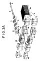
- Figs. 3A and 3B are schematic diagrams illustrating an embodiment of this invention.
- bags hereinafter also called as products S
- separator 12 which is to convert the flow of the products S into three lines, and subsequently the products are fed to centralizer 13 where the products are made to partially overlap each other.
- products inserting unit 14 is provided, which are shown in Figs. 7A - 7D and 8A - 8E, but not shown in Figs.
- support plate is provided to stand by to support products from underneath with variable height thereof in compliance with the stacked height of products in the carton.
- FIG. 8A to 8E Also another embodiment of apparatus shown in Figs. 8A to 8E is disclosed herein, which without using such support plate, enabling products to pack into bottom closed carton directly, and height of the vacuum pads which hold products can be varied depending upon the stacked height of products in the carton.
- the above mentioned apparatus is connected to said automatic carton assembler 15, and carton loading mechanism 16 where transfer sub-assembled carton to exact below position of products inserting unit.
- the reference numeral 4a indicates the stacking of flatted carton sheets and the numeral 4b illustrates the state of the carton after products are packed therein and flaps are closed.
- the reference numerals attached to the carton after assembled will be explained as follows; of the four flaps extending upper part of the carton, the numeral 4c indicates upper dust flaps which are perpendicular to the direction of progression; upper side flaps 4d are located next to said flaps 4c and are located parallel to the direction of progression of products. Similarly among flaps extending underneath, flaps perpendicular to the direction of progression of products are bottom dust flaps 4e and flaps along the direction of progression are bottom side flaps 4f.
- Figs. 38 and 4A-4B many folded sheets of cartons 4a which are being glued and kept flattened are drawn from magazine 30 one by one using vacuum pads 31 which moves reciprocally.
- a flat carton sheet is now assembled to a square box and then it will be guided to carton loading unit 16 which is located next to assembler 15.
- Numeral 35 indicates a pressure plate which pushes flattened carton sheets 4a stored in magazine 30 one by one in the direction shown by the arrow in Fig. 3A.
- Pressure plate 35 is attached to driving chain 36 which is connected to sprockets 36a, 36b, while said carton sheets 4a are located on catapillar 37 which moves in synchronism with said chain. Said sheets 4a will be taken from magazine 30 one by one by vacuum pad 31. At that time, carton sheet 4a is assembled to form a carton box 4 by guides 32, 33, etc.
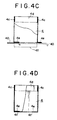
- Fig. 4B shows the appearance of carton box 4 after being assembled by the above mentioned method. All flaps are open vertically, however, when this carton is transferred from assembler 15 to the adjacent loading mechanism 16, flaps are bent as shown in Fig. 4C. Namely, among bottom flaps, bottom side flaps 4f are open vertically.
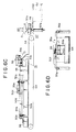
- the loading mechanism consist of the drives (refer to Figs. 5A and 5B) for feeding assembled carton 4 to the left and a slider (refer to Fig. 5C).
- driving units are located at both sides of said slider as explained below. Namely, as shown in Fig. 5A, driving units (refer the numerals of 41, 42) are located at both sides of loading mechanism 16 and pull forward or push the carton 4 from behind, by using vacuum pads. These driving units make carton 4 on bottom plate 40 to move forward one by one.
- the said driving units, except one shown by numeral 42, can move longitudinally, only the part shown by numeral 42 is fixed and does not move longitudinally.
- the driving units shown by numeral 41 consist of rodless cylinder 43 which is located parallel to the longitudinal direction of the loading mechanism and swing mechanism which is fixed on the piston table of cylinder 43.
- the above mentioned swing mechanism as shown in Fig. 5B consists of rack 41a, pinion 41b and swing arm 41c which is driven by said pinion 41b.
- some are equipped with suction pad 44 at the working end which is located at the right hand end in Fig. 5A.
- Fig. 5A is a general arrangement showing where said driving units are located. Except for the fixed one, all others can move longitudinally. Swing arm 41c located on said cylinder moves to the left and right in a reciprocal motion along said cylinder as shown in the figure by rodless cylinder 43.
- Said swing arms 41c or 42c both make a quarter circle around the pinion shaft as shown by arrow in Fig. 5A sending carton forward and will be reset to the original position after this action.
- the numeral 44 indicates brake cylinder mechanism which positions said carton box to a predetermined position in the transfer path.
- the end of bottom rail 40 is connected to support plate 45 which moves up and down within the square box.
- Said support plate is attached to cylinder 46 at bottom thereof.
- the above is an embodiment of a method of assembling flattened carton sheets into a square carton and transferring the carton to a packing position (x) under the open top condition thereof.
- the above explanation is a process to fold and transfer carton in the state shown in Fig. 4C, the mechanism shown in Figs. 5C, 5D are not necessary to be used, and mechanism shown in Figs. 5A, 5B may be used. Therefore, the explanation made for Figs. 5A, 5B are also referred to the assembled carton as shown in Fig. 4D. Next, the process of transferring products to said packing position will be explained.
- an embodiment of this invention features a method to form plural lines, for example three lines, with bags partially overlapping and then to placed bags stacked step by step in a carton. Accordingly it is immaterial if a separator is used or not. Bags can be fed in single line and converted to plural lines using a separator. Or alternatively, if the bags are already fed in plural lines, it is not necessary to use a separator.
- a separator which converts a single line into three lines is explained as follows.
- the numeral 12 in Fig. 3B indicates the separator.
- Belt conveyor 11 is placed before the said separator and products are supplied to said separator 12 one by one through conveyor.
- Said distributor consists of pivot 50a located at the entrance side, two distributing plates 50b, 50b which are connected to said pivot and free of rotational movement, and interconnector 50c which connects said two distributing plates and causes the following synchronized motion. Firstly in order to allow a product to go straight ahead, nothing said distributing plates swing neither left nor right, allowing a product fed in single line to be distributed either to the left or right. Alternatively switching to three positions, products fed in a single line are distributed to three lines. Once products distributed in three lines are accumulated by stopper 51, they are collectively aligned in transverse, and then fed to the succeeding centralizer.
- Figs. 6B and 6C are details of said separator, and said distributing plates 50b can take any of three positions as mentioned above, i.e. middle, left or right alternatively by driving units 50e.
- the distributor 50 is located on frame 50d as shown in Fig. 6B.
- This apparatus consists of two air cylinders (one air cylinder 50e is fixed on said frame and the other 50f is movable in relation to said frame), frames for sliding plate 52a, 52b which guide said movable cylinder 50f and sliding plate 53 which is fixed to the working end of piston rod of above mentioned cylinder 50e.
- Said interconnector 50c is movably attached through a long hole 53a.
- distributing plates 50b, 50b is connected to pivot 50a which is located on frame 50d, the other side being connected to movable shafts 50g which are connected to said interconnector 50c.
- this interconnector moves, as sliding plate 53 moves, to and stops at the middle, left or right position alternatively, said distributing plates 50b, 50b repeat the similar movements and as a result prods are distributed.
- Figs, 6B and 6C all above mentioned parts are provided on the wide belt conveyor 54.
- ⁇ Driving plates 55 are located at before said distributor 50.
- the space between said driving plates corresponds to the gap of two distributing plates.
- Accumulation stopper 51 which momentally accumulates products is located at the forward end of said distributing plates.
- Said accumulation stopper consists of stopping plate 51b which is openable by pin 51a, cylinder 56 which opens and closes said plate, and sensor 51d to detect if 3 products are aligned at said plate position.
- Said stopping plate opens and closes at the signal detected by limit switches LS-1 to LS-3.
- Said apparatus causes a single line of products to be converted to three lines.
- Products S brought in a single line by said belt conveyor 11 are fed to guide 56 on the entrance side and flow in between said distributing plates 50b, 50b.
- Distributing plates moving intermittently by driving unit of said cylinder 50e, 50f take firstly either left or right position then to the middle position as shown as solid line in the figure, and then to the remaining position of side, to be converted in three steps in order, so as to distribute products to be in three lines.
- the first fixed cylinder 50f causes the said second movable cylinder 50e, which is attached to its piston rod, to slide.
- Sliding plate 53 which is attached to said movable cylinder 50e, moves transversely with belt conveyor along sliding frame 52b.
- Interconnector 50c moves to the left and right, resulting in a required motion.
- accumulated stopper 51 is provided at the forward end of distributing plates to align products.
- cylinder 56 is activated to release said stopper and products in three lines are then unloaded from belt conveyor 54.
- Products unloaded from said conveyor 54 are fed onto lifter 57 and then moved to the centralizer, the explanation of which follows.
- said lifter 57 consists of elevation movable tray 57a, whose section is L shape and located at the end of belt conveyor 54, and cylinder 57b which supports and lifts the tray up and down.
- tray 57a When tray 57a is empty, said tray is waiting at the same level at the unloading end of said belt conveyor 54.
- a sensor which is not shown in the figure sends a signal to make said tray to move up, as shown as in dotted line, and to transfer products to vacuum pads 62, 64.
- FIG. 7A to 7C designates the frame of the centralizer
- numeral 61 designates a sliding guide rod, free movably located on frame 60.
- Sliding rod 61 is located transversely of frame 60 and can slide along the direction of progression of products.
- Numerals 62 to 64 designate vacuum pads to individually hold said products by suction and can move perpendicularly to the direction of progression of products. In this example, as shown in Fig.
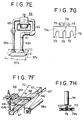
- this vacuum pad consists of two suction pipes across said sliding guide rod 61 and a roller bearing 65 which enables said suction pipes to slide longitudinally direction on said sliding guide rod 61. It is, in practice, immaterial if the number of vacuum pipes is one or more. Suction pads are attached at the end of vacuum pipes which directly touch products S and carry out lift up and down motions as shown in Fig. 7D.
- sliding guide rod 61 is located on left and right guide rails 67 which are hanging over supporting block 66.
- One of two supporting blocks is connected to piston rod 68a of air cylinder 68 which is fixed on frame 60. When said cylinder 68 is in motion, sliding guide rod 61 moves reciprocally on guide rail 67 parallel to the direction of progression of products.
- three vacuum pads 62 to 64 can move along said sliding guide rod 61.
- the one located at the center 63 is fixed to sliding guide rod 61 and vacuum pads located at both sides 62 to 64 can move longitudinally with sliding guide rod 61.
- Supporting block 66 which supports vacuum pads on both sides enables sliding guide rod to move along the direction of progression of products on sliding guide rail 67.
- said vacuum pad 62 (same as vacuum pad 64) is equipped with roller 69 at its bottom and this roller touches cam follower 70, whose shape is triangular at the inside of guide rail 67.
- Spring 71 which always pulls said vacuum pads to the sides is located between vacuum pads 62 to 64 and supporting block 66 as shown in Figs.
- Products transferred on said lifter 57 touch vacuum pads which are waiting right above, as said lifter has been lifted up by cylinder 57b.
- Accumulation stopper 51b is located at the front end of said lifter which aligns the position of products at the same location. Retaining the state of being aligned of three products transversely, products will touch vacuum pads by means of the lifter. Said vacuum pads which are connected to a vacuum pump have already started suction. Therefore, as soon as products touch said pads, they will be held by suction, and are moved forward maintaining this status. Furthermore, while they are advancing, vacuum pads 62 to 64 which are located at both sides will converge to the center by the cam follower reaction.
- the overlapping margin can be determined by adjusting the distance between the center of the bag and the position where the bag is held by suction. Said margin can be adjusted in each application.
- elevation movable wave shaped table 100 is provided at exit side (unloading end) of belt conveyor 54 shown in Fig. 6C, and transversely aligned products fed through said conveyor 54 are transmitted onto this table.
- pillow plate 101 of which number corresponds to the products number to be fed are secured in inclined state so that all transmitted products onto said table become automatically oriented with same inclination along with said pillow plates.
- air cylinder 102 is provided to direct the up-down motion of said table, and guide rods 103, 103 are fixed on both sides of said cylinder 102.
- L-shaped flange plate 104 For prevention from fallen off the transmitted products onto said table, plain view of L-shaped flange plate 104 are protruded on the edge end of said table 100. Further, on slightly upper portion of both sides of said table, position sensor 105 such as photo sensors are provided to detect the table position as to whether it ascends to proper position.
- vacuum pads 110 are provided to suck and transmit products placing on the table.
- the layout of these vacuum pads 110 should be made at some extent off-center from the center line C of product S, more precisely at position where leaned more higher position (as shown on dotted line as C′ in Fig. 8B) of the inclined pillow plates on the table. Under such structure, when products S are transmitted onto the wave shaped table 100 through conveyor 54, such products are placed on the table as inclined in compliance with the inclination of said pillow plates 104.
- position sensor 105 stand by at upper portion of said table, thereby the existence of products on said table are confirmed, and said table 100 is lifted up by the motion of air cylinder 102 with the confirmation signal.
- vacuum pads 110 are waiting while keeping suction state thereof, and then they contact and suck said products S by suction effect.
- operation line C′ of vacuum pads is leaned from center line C of products in the direction of up and down, therefore they are transfered to succeeding process of products packing, while they are in the condition that such sucked products are kept inclined and simultaneously they are partially overlapped each other.
- Products inserting unit is located, as shown in Figs. 7D and 7G, where vacuum pipes (62a, 62b etc) come to the end.
- Said inserting unit consists of vertically equipped cylinder 74 and contacting plate 72, which lifts up and down by means of said cylinder 74.
- Said contacting plate have incisions 73, 73 which enable vacuum pipes of vacuum pads 62 to 64 to enter.
- Numeral 72a designates a vibration absorption rubber attached on the surface where products touch, in order not to damage the contents when products are placed inserting. However it is not essential to use the vibration absorption rubber. It is also possible to use compressed springs 72b (Fig. 7H) between inserting plate 76 and contacting plate 72 as an alternative measure to avoid damage caused by impact when inserting products.
- Numeral 75 designates guide rod for cylinder 74.
- Contacting plate 72 by cylinder 74, retain products detaching them away from vacuum pads 62 to 64 so as to press products from above softly, then placed products inserting into the square carton 4 positioned just below thereof. Suction of vacuum pads is released as soon as the contacting plate 72 starts to move down by electrical signal.
- Products in three lines and being held by vacuum pads 62 to 64 as stated above are centralized and come closer while they are advancing, and depending on the necessity, they are partially overlapped. Since this embodiments enables the operator to choose a position where products is held by suction, an optimum overlapping margin can be obtained, depending upon types, weight and size of products.
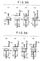
- Figs, 9A (1) to (16) schematically show the process by which products are packed in this position.
- supporting plate 45 has already been lifted up and products are forcibly retained by contacting plate 72 on this plate into carton as can be seen in Figs. 9A (3), (4).
- the support plate 45 is lowered gradually by a stepping air cylinder (or alternatively a lock cylinder may be used) located underneath.
- a stepping air cylinder or alternatively a lock cylinder may be used
- induction plate 80 is provided adjacent to support plate 45, and slide type of guide plate 81 whose driving source is cylinder 81a is provided underneath said induction plate to be partially overlapped each other.
- Similar slidable adjusting plate 82 is also provided at end part of guide plate 81, which will be driven by cylinder 82a.
- Bottom plate 83 to be covered by said slidable adjusting plate 82 is provided in such a manner that adjusting plate 82 can be come appeared from under bottom plate 83.
- both guide plate 81 and adjusting plate 82 are faced each other at the position of stand back as shown in dotted arrowed in Fig. 5D, bottom kicker to folds said dust flap, spring out in that space between said guide plate 81 and adjusting plate 82.
- Cylinder 84a is attached to frame 85, and flap folder 84c is engaged with piston rod 84b of said cylinder.
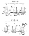
- This embodiment includes means for folding upper rear dust flap 4c of carton 4, using a similar mechanism as already explained above. Refer to upper kicker 86 in Fig. 10.
- Carton 4 is transferred from left to right one by one as shown in Fig. 5A using driving unit 41 and rodless cylinder 43.
- the rear bottom dust flap of said carton is folded on the way to transfer in the following manner. Firstly the front dust flap is folded taken by advance of carton 4 to the left, while it is sliding on fixed position of induction plate 80, protruded condition of guide plate 81, same protruding condition of adjusting plate 82, and fixed bottom plate 83.
- these guide plate 81 and adjusting plate 82 stand back to inside gradually, as shown in dotted arrow in Fig. 5D and Fig. 10 so as to create the sufficient space between plates 81 and 82 to hang down the rear bottom dust flap.
- the stroke of piston rod 125a thereof are adjustable by adjusting the number and location of reed switch 125b which is mounted on outer periphery of said cylinder, to make variable motion of stroke of said piston rod gradually and periodically.
- reed switch 125b which is mounted on outer periphery of said cylinder
- plain view of said transfer plate 124 has bear hand shape (glove shape), and total 3 indents 124a are formed at center and both sides thereof to insert said vacuum pads 122.
- plural number of vacuum pads 126 are mounted with different type than said vacuum pads 122 with elevation movably in some extent toward up-down direction through small air cylinder 126a which is mounted to said transfer plate.
- products S placed on lifter 57 are once lifted up by transversely reciprocatively movable vacuum pads 122, products are transfered to the exact below position of transfer plate, and when products reached to the exact below position of transfer plate, they are sucked by another vacuum pads 126 which is mounted to said transfer plate.
- vacuum pads 126 which are previously located underneath of said transfer plate are slightly lifted up through small air cylinder 126a, and when products reached to the exact below position of transfer plate, said pads 126 are lowered toward below, and then suction to products are applied. Thereafter, the suction of horizontally movable vacuum pads 122 are released, and products are transmitted to below side of transfer plate 124.
- lifter is exemplified as shown by numeral 57, however, substituted for this lifter, elevation movable wave shaped table 100 shown in Figs. 8A, 8B may be used.
- driving units expressed to as cylinder means the air cylinder typically, but oil pressure, hydraulic or any other pressure source may be used. Electric motors can be used as a driving means.
- a vertical pillow type bag filling machine may be installed at before process of loading conveyor 11 mentioned in the above embodiment, synchronizing with weighing gauge to align bags converting single line thereof into plural lines after bags are sealed while weighing snack food and bagged.
Landscapes
- Engineering & Computer Science (AREA)
- Mechanical Engineering (AREA)
- Container Filling Or Packaging Operations (AREA)
Abstract
The present invention relates to a method and apparatus for packing flexible packages such as snack food bags, comprising splitting a single line of packages (5) on a conveyor into a number of separate lines in a separator (12) so as to provide transverse rows of packages, centralizing said packages in each row in a centraliser (13) so as to partially overlap each other, subsequently lifting up each row of centralised packages using vacuum pads (62,64), placing said packages into an open top outer carton (4) so as not to allow the packages to drop by gravity; the rows being stacked in tiers in the carton.
Description
- The present invention relates to a method and apparatus for packing bagged products, or more precisely a method and apparatus for automatically packing so called flexible packages containing snack foods or the like (hereinafter referred to as "bags") into a container while bags are in condition to be aligned and overlapped each other partially.
- When transporting, storing or handling bags, it is necessary to pack a set quantity of bags into a container such as corrugated carton. Although packing bags in a carton or the like has been universal, it is fact that no satisfactory method or apparatus for packing bags is known or developed with a view to protecting the contents, as will now be described.
- There are many problems in packaging and packing bags, especially bags of snack foods or the like, since snack foods such as potato chips, pop corn, corn chips or the like have the common characteristic that they can be easily damaged, absorb moisture, their flavour may be changed, etc. In particular, that they can be easily damaged presents the biggest problem. To be more precise, since snack food packages are not even in shape with concavo-convex and they have a large surface area, the likehood of the contents being damaged during the time from when products have been shipped from manufacturers to when they reach to consumers through various kinds of distribution passages, thereby consequent deterioration of commodity value can frequently occur. To prevent this from happening at the moment a certain amount of air, nitrogen gas or the like, is enclosed with the bag together with contents, when bagging the products. However, bags in which air or gas is enclosed together with goods are bulky and packing of such balloon-like bags into a carton can only be carried out manually, since these bags need to be partially overlapped when packing. In addition, a bag within which air or gas is enclosed gradually shrinks and reduces size thereof complied with the decreasing temperature of said products after packing. Furthermore, it is inevitable that air or gas enclosed in a bag, although it depends on air tightness or sealing capability thereof, gradually leaks on the duration of distribution channels therethrough. Under the above mentioned circumstances, the size of the bag is gradually reduces, after being packed, and gaps between bags within the carton frequently occur.
- In the meantime, the apparatus itself for packing bags automatically is conventionally known, for example, Japanese Laid Open Publication Nos. Showa 59-134105 or Showa 60-23105 discloses. However, since that invention relates to a method of packing bags into a carton one by one to be overlapped each other partially through a belt conveyor, therefore, it is neither efficient to handle a large number of bags at a time nor suitable for handling many bags at high speed. Moreover, the former invention was developed for packing relatively heavy goods such as "instant" fresh noodles, and therefore is not suitable for packing said flexible packages because flexible packages are light weight and tend to suspend by air resistance when an attempt is made to drop packages in a set position, resulting in dislocation.
- On the other hand, the latter apparatus, using a motion arm equipped with vacuum pads, bags fed by loading conveyor are transmitted onto a carton while keeping suction by said arm, and drops the bags within a carton by releasing suction of said pads. This method requires a bigger carton since a bag drops aslant if even a corner of the bag touches the edge of the carton. This results in a gap between bags after packing.
- For the reasons of efficiency and economy, it is desirable to pack bags as tightly as possible into a carton in order to avoid gaps between bags especially when bags reduce their size after packed and shrunk of bags. However is is not able to carry out such tight packing and consequently there is no choice but to do it manually.
- In the meantime, recently, a method has been proposed that using an actuator like a robot affixed with vacuum pads, the plural bags fed by belt conveyor are picked up by said vacuum pads, once turned to side or transfered horizontally, and then said actuator is lowered to pack said bags into a carton. However, on this method, it is necessary to give 3 discontinuous motions for picking up, down and turning for bags to an actuator, so that resultant was inconvenience with extremely slow operation speed, thereby it is caused inferior operation efficiency.
- The present invention makes it possible that, for packing the above mentioned flexible packages (bags) into a container such as carton or the like, making plural bags to be aligned transversely under the condition of overlapping partially from the beginning, packing bags into carton forcibly so as to retain them through a contacting plate, and conversely, elevation movable support plate stand by in the carton so as to receive bags quietly by supporting them from underneath being inserted from above, thereby it precludes bags from giving impact by dropping. Also the present invention is to provide an apparatus that a plural number of bags aligned transversely under the condition of partially overlapped are directly holden by vacuum pads which are movable in elevationally and horizontally, holdings are directly inserted into an open top carton whereby vacuum of the vacuum pads are released in the vicinity of the loading position of the bags in the carton, thereby said elevation movable support plate is not necessary to be used. As such above, at the time of packing said bags into a carton, they can be packed neatly within a carton without reflection to those even if the end of said bags touch to the flip top of the carton.
- In the method for packing bags in accordance with this invention, the bags are firstly formed in plural lines along a direction of progression, they are held by suction by vacuum pads simultaneously, they converged to the center keeping inclined with neighbouring bags being partially overlapped, they are transmitted to be above position of carton, and finally packed into the carton.
- Furthermore, embodiments of this invention include a method and apparatus to convert the flow of bags from single line to multiple lines on the way of transportation, and a method and apparatus to seal a carton after packing of bags into the carton is completed.
- The first object of this invention aims to provide a method and apparatus that makes it possible to pack flexible packages, enclosed with air or gas, tightly in a carton with packages partially overlapped. The second object is to pack bags tightly in a carton, thus eliminating unwanted gaps between bags are reduced, even if the size of bags is reduced because of leakage of air or gas from the bags. The third object of this invention is that many bags can be packed into a carton within a short time by operating the packing apparatus at higher speeds than conventional machines.
- The present invention provides an appropriate method and apparatus for packing flexible packages such as snack foods which have characteristics of being easily damaged, absorption of moisture, altering of flavour, etc. Air or gas inside of bag often leaks, while being transported, stored or going through any other handling routines, resulting in damage to contents and deterioration of commodity value. Since embodiments of this invention enable products to be aligned in plural lines, centralized with partial overlapping, placed products inserting into a carton by supporting them from above and under, the damage to products is minimized by tightly packing products in carton, thus avoiding movement of products in the carton when they are handled during transportation or storing or at any other occasion.
- Embodiments of this invention make it possible to pack products in carton by retaining them so as to press them softly, therefore, products can be tightly packed, even if products project out slightly of the carton as bigger size. Embodiments of the invention provide a practical solution for tight packing.
- Moreover, it is possible to pack bagged products, which are flexible, after bags being aligned, being partially overlapped, packed in carton, and sealing the carton by applying pressure on both upper and bottom flaps of the carton. Therefore it is more beneficial since this arrangement does not require as big carton as required by conventional methods and thus, facilitates more efficient packing and reducing packing cost.
- Furthermore, by means disclosed it is possible to achieve automation for packing thus abolishing manual packing which reduces operational costs.
- The present invention will now be described by way of example with reference to the accompanying drawings, in which:
- Fig. 1A is a perspective view of a bag suitable to be deal with by this invention;
- Fig. 1B is a longitudinal section view of said bag;
- Fig. 2A is an isometric view of bags after they have packed in a carton (front part of the carton has been eliminated for explanation purpose);
- Fig. 2B, 2C are section view of cartons illustrating typical packing problems frequently encountered when using conventional apparatus;
- Fig. 3A is an isometric view showing bags being fed in one line then converted to 3 lines and being packed in a carton after being partially overlapped. A process in which flattened carton sheets are assembled and bags are packed in said carton is also shown;
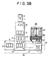
- Fig. 3B is a front view of Fig. 3A;
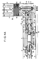
- Fig. 4A is a plain view showing an automatic carton assembler and loading mechanism of the carton after assembled in accordance with an embodiment of this invention;
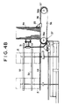
- Fig. 4B is a side elevational view of the automatic assembler of Fig. 4A;
- Fig. 4C is a section view showing a part of process of folding the dust flaps of carton on the way of carton assembling;
- Fig. 4D is a section view showing a bottom closed condition by conventional method without applying special folding process;
- Fig. 5A is a plain view showing an entire arrangement of main driving unit of said carton loading mechanism of Fig. 4A;
- Fig. 5B is a plain view showing part of driving unit of Fig. 5A;
- Fig. 5C is a side elevational view showing, in the loading mechanism of Fig. 4A, means for supporting the bottom of a carton and means for folding bottom dust flaps of the carton;
- Fig. 5D is a section view of Fig. 5C showing respective driving motion thereof;
- Fig. 6A is a schematic diagram to explain how the bags fed in single line are separated and converted to plural lines;
- Fig. 6B is a plain view of the separator of Fig. 6A;
- Fig. 6C is a side elevational view of the separator of Fig. 6B;
- Fig. 6D is a section view taken along with VI-VI line of Fig. 6B;
- Fig. 7A is a plain view of a centralizer to make bags to be partially overlapped transversely fed from plural lines;
- Fig. 7B is a rear elevation view of the centralizer of Fig. 7A;
- Fig. 7C is a schematic diagram showing part of sliding mechanism of sucked bags to transverse direction;
- Fig. 7D is a side elevation view of the centralizer of Fig. 7A, also showing up-down mechanism of contacting plate to pack the bags forcibly into a carton keeping suction thereto;
- Fig. 7E is a side elevation view showing details of means for holding bags by suction;
- Fig. 7F is an isometric view showing a cam mechanism which makes said means for holding bags by suction to slide transversely;
- Fig. 7G is a plain view showing the underneath of said contacting plate;
- Fig. 7H is a side elevation view showing an another embodiment of the contacting plate;
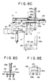
- Figs. 8A to 8E show an another embodiment of an apparatus of centralizer to make bags to be partially overlapped transversely from plural lines, and while centralized bags are sucked, they are transmitted to the position onto the open top of carton and packed therein, whereas,
- Fig. 8A is an isometric view,
- Fig. 8B is an elevational view,
- Fig. 8C is a side elevational view of the apparatus to pack the bags,
- Fig. 8D is an elevational view showing elevation movable mechanism, and,
- Fig. 8E is a plan view showing an arrangement of vacuum pads;
- Figs. 9A (1) to (16) are the schematic diagrams showing how bags are tiered in multiple steps;
- Fig. 9B are the schematic diagrams showing the process to tier the bags in the carton using a packer shown in Figs. 8C to 8E;
- Figs. 10 (1) to (6) are schematic diagram showing the order of folding side flaps and dust flaps of the carton;
- Fig. 11 is a side elevation view showing means for folding said side and dust flaps of the carton; and
- Fig. 12 is a rear view of Fig. 11.
- By reference to figures, embodiments of this invention will be explained in details. Figs. 1A, 1B show an example of
bag 1 made from material with good gas barrier properties; for example aluminium vacuum metalized plastic film is packed withsnack foods 2, andair 3 is enclosed therein during the bagging thereof. The length of the bag is designated by 1, and the length of corrugate carton is designated by L as an outer case in which the bags are to be packed. In this invention, for example, three bags are aligned in transverse direction, they are overlapped each other partially, and they are packed in the carton so as to be arranged in tiers stepwisely vertically in the carton, as shown in Fig. 2A. - The aforementioned conventional methods cause problems for example, gaps between bags S within a carton occur or bags are loosely packed in a carton as shown in Fig. 2B. Bags are often dropped and placed in a wrong position within a carton if the bags touch the upper edge of the carton as shown in Fig. 2C. When packing three bags horizontally, the existing art require L′ > 31. The present invention enables the dimension to be L < 31. Therefore, according to the present invention, the carton size to pack the bags can be smaller compared with the conventional one. In other word, the carton shown in Fig. 2A can be smaller than one shown in Fig. 2B in the developed dimension, that means so much saving the material cost.
- Figs. 3A and 3B are schematic diagrams illustrating an embodiment of this invention. To start with, the general arrangement will be explained, for example, bags (hereinafter also called as products S) fed by
belt conveyor 11 in a single line are introduced toseparator 12 which is to convert the flow of the products S into three lines, and subsequently the products are fed to centralizer 13 where the products are made to partially overlap each other. At the unloading end of said centralizer,products inserting unit 14 is provided, which are shown in Figs. 7A - 7D and 8A - 8E, but not shown in Figs. 3A - 3B, and which enable the products to be placed in the carton forcibly while retaining them so as to press them from above softly with products being aligned transversely and partially overlapped. As explained later, in the carton, support plate is provided to stand by to support products from underneath with variable height thereof in compliance with the stacked height of products in the carton. - Also another embodiment of apparatus shown in Figs. 8A to 8E is disclosed herein, which without using such support plate, enabling products to pack into bottom closed carton directly, and height of the vacuum pads which hold products can be varied depending upon the stacked height of products in the carton.
- As shown in Fig. 3B, the above mentioned apparatus is connected to said
automatic carton assembler 15, andcarton loading mechanism 16 where transfer sub-assembled carton to exact below position of products inserting unit. In Figs. 3A and 3B, thereference numeral 4a indicates the stacking of flatted carton sheets and the numeral 4b illustrates the state of the carton after products are packed therein and flaps are closed. Using Fig. 4C, the reference numerals attached to the carton after assembled will be explained as follows; of the four flaps extending upper part of the carton, the numeral 4c indicates upper dust flaps which are perpendicular to the direction of progression; upper side flaps 4d are located next to saidflaps 4c and are located parallel to the direction of progression of products. Similarly among flaps extending underneath, flaps perpendicular to the direction of progression of products arebottom dust flaps 4e and flaps along the direction of progression arebottom side flaps 4f. - The details of each part of the apparatus will now be explained by reference to the drawings. Even though this invention relates to a method and apparatus for packing a number of bags into a carton, a
carton assembler 15, andcarton loading mechanism 16 to transfer sub-assembled carton will be briefly explained so as to provide a better understanding of the environment to which the invention is applicable. Then separator 12 which is connected to beltconveyor 11,centralizer 13 andproduct inserting unit 14 will be explained. - As shown in Figs. 38 and 4A-4B, many folded sheets of
cartons 4a which are being glued and kept flattened are drawn frommagazine 30 one by one usingvacuum pads 31 which moves reciprocally. At the same time, usingguides guide rail 34 as shown in dot-dash lines in the figure, a flat carton sheet is now assembled to a square box and then it will be guided tocarton loading unit 16 which is located next toassembler 15.Numeral 35 indicates a pressure plate which pushes flattenedcarton sheets 4a stored inmagazine 30 one by one in the direction shown by the arrow in Fig. 3A.Pressure plate 35 is attached to drivingchain 36 which is connected tosprockets carton sheets 4a are located oncatapillar 37 which moves in synchronism with said chain. Saidsheets 4a will be taken frommagazine 30 one by one byvacuum pad 31. At that time,carton sheet 4a is assembled to form acarton box 4 byguides carton box 4 after being assembled by the above mentioned method. All flaps are open vertically, however, when this carton is transferred fromassembler 15 to theadjacent loading mechanism 16, flaps are bent as shown in Fig. 4C. Namely, among bottom flaps,bottom side flaps 4f are open vertically. Onlybottom dust flaps 4e advance to the left inloading mechanism 16, byguide rails rear flaps 4e are bent to the right as shown in Fig. 4C. In other words, the bottom dust flaps are bent to the right bybottom rail 40. By this way, the cartons in opened state are loaded further by loading unit to the insertingunit 14 which will be explained later. - In this connection to assemble carton in the present invention, without applying folding process as shown in Fig. 4C, only bottom flap of carton are previously closed according to the conventional method in manner shown in Fig. 4D, thereafter, it may be introduced to inserting
unit 14 through belt conveyor as generally utilized. - By referring to Figs, 5A - 5D, the process of carton loading mechanism in which each flap of said carton is folded one by one and transfered will be explained as follows.
- The loading mechanism consist of the drives (refer to Figs. 5A and 5B) for feeding assembled
carton 4 to the left and a slider (refer to Fig. 5C). Several driving units are located at both sides of said slider as explained below. Namely, as shown in Fig. 5A, driving units (refer the numerals of 41, 42) are located at both sides ofloading mechanism 16 and pull forward or push thecarton 4 from behind, by using vacuum pads. These driving units makecarton 4 onbottom plate 40 to move forward one by one. The said driving units, except one shown bynumeral 42, can move longitudinally, only the part shown bynumeral 42 is fixed and does not move longitudinally. Namely, the driving units shown by numeral 41 consist ofrodless cylinder 43 which is located parallel to the longitudinal direction of the loading mechanism and swing mechanism which is fixed on the piston table ofcylinder 43. The above mentioned swing mechanism as shown in Fig. 5B consists ofrack 41a, pinion 41b andswing arm 41c which is driven by said pinion 41b. In a typical swing mechanism, some are equipped withsuction pad 44 at the working end which is located at the right hand end in Fig. 5A. Fig. 5A is a general arrangement showing where said driving units are located. Except for the fixed one, all others can move longitudinally.Swing arm 41c located on said cylinder moves to the left and right in a reciprocal motion along said cylinder as shown in the figure byrodless cylinder 43. Saidswing arms bottom rail 40 is connected to supportplate 45 which moves up and down within the square box. Said support plate is attached tocylinder 46 at bottom thereof. - The functions of the driving units are explained as follows; a square carton, just after being assembled, is pulled on the upper surface of
bottom rail mechanism 41 equipped withvacuum pad 44. Aftersuction pad 44 having moved a fixed distance,swing arm 41c equipped withpad 44, as shown by dot-dash arrow line in the figure, turns to make room for the carton to advance. Then other driving units 41 (shown in dot-dash arrow line in Fig. 5A) are activated to push said carton forward from behind. By this way the square carton which is pulled out byvacuum pad 44 onbottom rail 40 reaches the position shown as the numeral (x) in Fig. 5A. When the carton reaches the position (x),swing arm 42c of drivingunit 42 which is fixed in a position and the above mentionedswing arm 41c of drivingunit 41, which is movable, grab saidcarton 4 firmly from front and behind. As shown in Figs. 5C and 5D,support plate 45 is waiting at the position (x), and will move up within said carton bylock cylinder mechanism 46 as shown in the figure. Thiscylinder mechanism 46 is capable of stopping as plural steps at height. Said lock cylinder in the figure is variable at height by five steps in order. Thereby, products S are placed on saidsupport plate 45 and as the number of steps increases, said support plate lowers its position intermittently by using saidlock cylinder mechanism 46, until the carton is filled with products. As explained later, after products are tiered in five steps on thesupport plate 45, saidplate 45 is pulled out ofcarton 4 and located at the same height as saidbottom rail 40. - The above is an embodiment of a method of assembling flattened carton sheets into a square carton and transferring the carton to a packing position (x) under the open top condition thereof. The above explanation is a process to fold and transfer carton in the state shown in Fig. 4C, the mechanism shown in Figs. 5C, 5D are not necessary to be used, and mechanism shown in Figs. 5A, 5B may be used. Therefore, the explanation made for Figs. 5A, 5B are also referred to the assembled carton as shown in Fig. 4D. Next, the process of transferring products to said packing position will be explained.
- As stated above, an embodiment of this invention features a method to form plural lines, for example three lines, with bags partially overlapping and then to placed bags stacked step by step in a carton. Accordingly it is immaterial if a separator is used or not. Bags can be fed in single line and converted to plural lines using a separator. Or alternatively, if the bags are already fed in plural lines, it is not necessary to use a separator. However, as an embodiment of this invention, a separator which converts a single line into three lines is explained as follows.
- The numeral 12 in Fig. 3B indicates the separator.
Belt conveyor 11 is placed before the said separator and products are supplied to saidseparator 12 one by one through conveyor. - The details each components of the separator are as shown in Figs. 6A to 6D. General idea is explained using Fig. 6A; products S fed from the left to the right are introduced to
distributor 50, and the products in plural lines are then aligned transversely byaccumulation stopper 51. - Said distributor consists of
pivot 50a located at the entrance side, two distributingplates interconnector 50c which connects said two distributing plates and causes the following synchronized motion. Firstly in order to allow a product to go straight ahead, nothing said distributing plates swing neither left nor right, allowing a product fed in single line to be distributed either to the left or right. Alternatively switching to three positions, products fed in a single line are distributed to three lines. Once products distributed in three lines are accumulated bystopper 51, they are collectively aligned in transverse, and then fed to the succeeding centralizer. - Figs. 6B and 6C are details of said separator, and said distributing
plates 50b can take any of three positions as mentioned above, i.e. middle, left or right alternatively by drivingunits 50e. Thedistributor 50 is located onframe 50d as shown in Fig. 6B. This apparatus consists of two air cylinders (oneair cylinder 50e is fixed on said frame and the other 50f is movable in relation to said frame), frames for slidingplate movable cylinder 50f and slidingplate 53 which is fixed to the working end of piston rod of above mentioned cylinder 50e. Said interconnector 50c is movably attached through along hole 53a. One side of said distributingplates frame 50d, the other side being connected tomovable shafts 50g which are connected to saidinterconnector 50c. As this interconnector moves, as slidingplate 53 moves, to and stops at the middle, left or right position alternatively, said distributingplates wide belt conveyor 54. - Four driving
plates 55 are located at before saiddistributor 50. The space between said driving plates corresponds to the gap of two distributing plates.Accumulation stopper 51 which momentally accumulates products is located at the forward end of said distributing plates. Said accumulation stopper consists of stopping plate 51b which is openable by pin 51a,cylinder 56 which opens and closes said plate, and sensor 51d to detect if 3 products are aligned at said plate position. Said stopping plate opens and closes at the signal detected by limit switches LS-1 to LS-3. - Said apparatus causes a single line of products to be converted to three lines. Products S brought in a single line by said
belt conveyor 11 are fed to guide 56 on the entrance side and flow in between said distributingplates cylinder fixed cylinder 50f causes the said secondmovable cylinder 50e, which is attached to its piston rod, to slide. Slidingplate 53 which is attached to saidmovable cylinder 50e, moves transversely with belt conveyor along slidingframe 52b. Interconnector 50c moves to the left and right, resulting in a required motion. - Products distributed in three lines are not aligned at same time and therefore accumulated
stopper 51 is provided at the forward end of distributing plates to align products. When three sensors 51d and limit switches LS-1 to LS-3 detect that all products are at the stopping position in each line, thencylinder 56 is activated to release said stopper and products in three lines are then unloaded frombelt conveyor 54. Products unloaded from saidconveyor 54 are fed ontolifter 57 and then moved to the centralizer, the explanation of which follows. As shown in Fig. 6C, saidlifter 57 consists of elevationmovable tray 57a, whose section is L shape and located at the end ofbelt conveyor 54, andcylinder 57b which supports and lifts the tray up and down. Whentray 57a is empty, said tray is waiting at the same level at the unloading end of saidbelt conveyor 54. When products are supplied on this, a sensor which is not shown in the figure sends a signal to make said tray to move up, as shown as in dotted line, and to transfer products tovacuum pads - Products on
tray 57a are held and lifted up by vacuum pads which form part of the centralizer as shown in Figs. 7A to 7C. While products are hung, products located at both sides go closer to the center until they are partially overlapped. More detailed explanation is given below. In figs. 7A to 7C, numeral 60 designates the frame of the centralizer, the numeral 61 designates a sliding guide rod, free movably located onframe 60. Slidingrod 61 is located transversely offrame 60 and can slide along the direction of progression of products.Numerals 62 to 64 designate vacuum pads to individually hold said products by suction and can move perpendicularly to the direction of progression of products. In this example, as shown in Fig. 7E, this vacuum pad consists of two suction pipes across said slidingguide rod 61 and aroller bearing 65 which enables said suction pipes to slide longitudinally direction on said slidingguide rod 61. It is, in practice, immaterial if the number of vacuum pipes is one or more. Suction pads are attached at the end of vacuum pipes which directly touch products S and carry out lift up and down motions as shown in Fig. 7D. As shown in Fig. 7A, slidingguide rod 61 is located on left and right guide rails 67 which are hanging over supportingblock 66. One of two supporting blocks is connected topiston rod 68a ofair cylinder 68 which is fixed onframe 60. When saidcylinder 68 is in motion, slidingguide rod 61 moves reciprocally onguide rail 67 parallel to the direction of progression of products. On the other hand, as stated above, threevacuum pads 62 to 64 can move along said slidingguide rod 61. Among the three vacuum pads, the one located at thecenter 63 is fixed to slidingguide rod 61 and vacuum pads located at bothsides 62 to 64 can move longitudinally with slidingguide rod 61. Supportingblock 66 which supports vacuum pads on both sides enables sliding guide rod to move along the direction of progression of products on slidingguide rail 67. At the same time said vacuum pad 62 (same as vacuum pad 64) is equipped withroller 69 at its bottom and this roller touchescam follower 70, whose shape is triangular at the inside ofguide rail 67.Spring 71 which always pulls said vacuum pads to the sides is located betweenvacuum pads 62 to 64 and supportingblock 66 as shown in Figs. 7A to 7C.Said vacuum pads 62 to 64 are pulled outward at all times along slidingguide rod 61. When said vacuum pads slide back and forth (along the direction of progression of products) by saidcylinder 68, vacuum pads at bothsides 62 to 64 converge to the center guided by cam follower 70 (when vacuum pads are advancing) or detach towards the sides (when retreating). The products inserting unit is located where saidvacuum pads 62 to 64 are in the most advanced position (in position shown in Fig. 7A). - Products transferred on said
lifter 57, as shown in dot-dash lines in Fig 7D, touch vacuum pads which are waiting right above, as said lifter has been lifted up bycylinder 57b. Accumulation stopper 51b is located at the front end of said lifter which aligns the position of products at the same location. Retaining the state of being aligned of three products transversely, products will touch vacuum pads by means of the lifter. Said vacuum pads which are connected to a vacuum pump have already started suction. Therefore, as soon as products touch said pads, they will be held by suction, and are moved forward maintaining this status. Furthermore, while they are advancing,vacuum pads 62 to 64 which are located at both sides will converge to the center by the cam follower reaction. The overlapping margin can be determined by adjusting the distance between the center of the bag and the position where the bag is held by suction. Said margin can be adjusted in each application. - When centering is over at the location shown in Fig 7A, products inserting unit shown as the numeral 14 (a solid line) in Fig. 7D is waiting to make the products to move in the following manner.
- Second embodiment of product centralizer is now explained in details according to Figs. 8A, 8B. In this embodiment, elevation movable wave shaped table 100 is provided at exit side (unloading end) of
belt conveyor 54 shown in Fig. 6C, and transversely aligned products fed through saidconveyor 54 are transmitted onto this table. As shown in Fig. 8B on said table 100,pillow plate 101 of which number corresponds to the products number to be fed are secured in inclined state so that all transmitted products onto said table become automatically oriented with same inclination along with said pillow plates. Underneath of said table 100,air cylinder 102 is provided to direct the up-down motion of said table, and guiderods cylinder 102. For prevention from fallen off the transmitted products onto said table, plain view of L-shapedflange plate 104 are protruded on the edge end of said table 100. Further, on slightly upper portion of both sides of said table,position sensor 105 such as photo sensors are provided to detect the table position as to whether it ascends to proper position. - On other hand, on the upper portion of said wave shaped table 100,
vacuum pads 110 are provided to suck and transmit products placing on the table. Although the structure and function of these vacuum pads are briefed later, the important matter here is that the layout of thesevacuum pads 110 should be made at some extent off-center from the center line C of product S, more precisely at position where leaned more higher position (as shown on dotted line as C′ in Fig. 8B) of the inclined pillow plates on the table. Under such structure, when products S are transmitted onto the wave shaped table 100 throughconveyor 54, such products are placed on the table as inclined in compliance with the inclination of saidpillow plates 104. At same time,position sensor 105 stand by at upper portion of said table, thereby the existence of products on said table are confirmed, and said table 100 is lifted up by the motion ofair cylinder 102 with the confirmation signal. On the upper part of the table 100, as mentioned above,vacuum pads 110 are waiting while keeping suction state thereof, and then they contact and suck said products S by suction effect. As aforementioned, operation line C′ of vacuum pads is leaned from center line C of products in the direction of up and down, therefore they are transfered to succeeding process of products packing, while they are in the condition that such sucked products are kept inclined and simultaneously they are partially overlapped each other. - As described above, by using an apparatus shown in Figs. 8A, 8B, it makes possible to have easier mechanical structure and shorter time of partial overlapping of product each other compared with the embodiment explained in accordance with Figs. 7A to 7H.
- Products inserting unit is located, as shown in Figs. 7D and 7G, where vacuum pipes (62a, 62b etc) come to the end. Said inserting unit consists of vertically equipped
cylinder 74 and contactingplate 72, which lifts up and down by means of saidcylinder 74. Said contacting plate haveincisions vacuum pads 62 to 64 to enter. Numeral 72a designates a vibration absorption rubber attached on the surface where products touch, in order not to damage the contents when products are placed inserting. However it is not essential to use the vibration absorption rubber. It is also possible to usecompressed springs 72b (Fig. 7H) between insertingplate 76 and contactingplate 72 as an alternative measure to avoid damage caused by impact when inserting products.Numeral 75 designates guide rod forcylinder 74. - Contacting
plate 72, bycylinder 74, retain products detaching them away fromvacuum pads 62 to 64 so as to press products from above softly, then placed products inserting into thesquare carton 4 positioned just below thereof. Suction of vacuum pads is released as soon as the contactingplate 72 starts to move down by electrical signal. - The above is the process in which three products are centralized, made to partially overlap and packed in a carton. Within said carton,
support plate 45 has been lifted up as shown in Fig. 5C, and products are placed through contactingplate 72 forcibly on this plate. - Products in three lines and being held by
vacuum pads 62 to 64 as stated above are centralized and come closer while they are advancing, and depending on the necessity, they are partially overlapped. Since this embodiments enables the operator to choose a position where products is held by suction, an optimum overlapping margin can be obtained, depending upon types, weight and size of products. - The position where products are inserted into
carton 4, as shown in Fig. 7D, is the position (X) as previously explained with reference to Figs. 5C, 5D. Figs, 9A (1) to (16) schematically show the process by which products are packed in this position. When products are centralized abovecarton 4, supportingplate 45 has already been lifted up and products are forcibly retained by contactingplate 72 on this plate into carton as can be seen in Figs. 9A (3), (4). After the first step of products are tiered, thesupport plate 45 is lowered gradually by a stepping air cylinder (or alternatively a lock cylinder may be used) located underneath. When the second step is tiered, theplate 45 moves further down and more steps of products are tiered thereto. - After a predetermined steps of products are tiered into
carton 4, which has been in the position (X), said carton will be pushed to the left to the position (Y), asswing arm 41a of drivingunit 41 which is located onrodless cylinder 43, as shown at upper left hand in Fig. 5A, is activated andswing arm 42 of fixed positioned drivingunit 42 which is located underneath is released as shown in dot-dash line. At the position (Y),brake cylinder 44 stops and fixescarton 4 and afterwards bottom flaps closing motions will be carried out. Namely, saidsupport plate 45 is pulled out fromcarton 4 and kept the same level withbottom rail 40. Among the four flaps extending from the bottom ofcarton 4, dust flaps 4e which are perpendicular to the direction of progression of products will be folded in the following manner. As stated above,carton 4 is moved to the left in Figs. 5A to 5D. Of the two dust flaps, the front dust flap is simply folded by pullingsupport plate 45 fromcarton 4. The remaining dust flap needs to be folded to the opposite direction. This folding mechanism will be explained. In the embodiment referring to Figs. 7A - 7H and 10 to 12, as shown in Figs. 5C, 5D,induction plate 80 is provided adjacent to supportplate 45, and slide type ofguide plate 81 whose driving source iscylinder 81a is provided underneath said induction plate to be partially overlapped each other. Similarslidable adjusting plate 82 is also provided at end part ofguide plate 81, which will be driven bycylinder 82a.Bottom plate 83 to be covered by saidslidable adjusting plate 82 is provided in such a manner that adjustingplate 82 can be come appeared from underbottom plate 83. When both guideplate 81 and adjustingplate 82 are faced each other at the position of stand back as shown in dotted arrowed in Fig. 5D, bottom kicker to folds said dust flap, spring out in that space between saidguide plate 81 and adjustingplate 82.Cylinder 84a is attached to frame 85, andflap folder 84c is engaged with piston rod 84b of said cylinder. - This embodiment includes means for folding upper
rear dust flap 4c ofcarton 4, using a similar mechanism as already explained above. Refer toupper kicker 86 in Fig. 10. -
Carton 4 is transferred from left to right one by one as shown in Fig. 5A using drivingunit 41 androdless cylinder 43. The rear bottom dust flap of said carton is folded on the way to transfer in the following manner. Firstly the front dust flap is folded taken by advance ofcarton 4 to the left, while it is sliding on fixed position ofinduction plate 80, protruded condition ofguide plate 81, same protruding condition of adjustingplate 82, and fixedbottom plate 83. When said flap passed on protrudedguide plate 81 and adjustingplate 82, theseguide plate 81 and adjustingplate 82 stand back to inside gradually, as shown in dotted arrow in Fig. 5D and Fig. 10 so as to create the sufficient space betweenplates rear dust flap 4e hangs down,arm 84c ofkicker 84 folds saidflap 4e, by means of itscylinder 84a at high speed, as shown in Figs. 10 (3), (4). Folded flaps advance, retaining this state, by guide ofbottom plate 83 etc which are located under said carton, keeping products withincarton 4 and preventing them from falling off. Upperrear dust flap 4c is folded in a similar manner bykicker 86 in Fig. 10. - Thereby each two of front and
rear flaps carton 4 are bent towards the desired direction. Meanwhile side flaps 4d, 4f of said carton are also bent and closed towards a predetermined direction by fixed guides 90 - 93 on the way of loading thereof as shown in Figs. 11 and 12. Hotmelt glue guns - Other than embodiment shown in Figs. 7A to 7H and 10 to 12, the following apparatus can be available to perform the present invention. Namely by using an apparatus shown in Figs. 8C, 8E, it is possible that the conveyor unit shown in Figs 5A, 5B can be combined used thereto, which is now described.
- Upper portion of
lifter 57 in Figs. 8C to 8E, horizontally extendingguide frame 121 is provided so as to cover the immediate above said lifter by top end of said frame. Tosuch guide frame 121,vacuum pads 122 is mounted having same mechanism as shown in Fig. 7E and having reciprocative motion between (X) point and (Y) point in the drawing along with longitudinal direction ofcylinder 123 which is mounted to said guide frame. At (Y) point,transfer plate 124 is provided for the purpose of transfer stacking with up-down motion but the position of horizontal direction thereof is fixed. Such up-down motion of said transfer plate is given by vertical shape of stepping air cylinder 125 (also called as lock cylinder) which is mounted to guideframe 121 as shown in the drawing. As to said steppingair cylinder 125, the stroke ofpiston rod 125a thereof are adjustable by adjusting the number and location ofreed switch 125b which is mounted on outer periphery of said cylinder, to make variable motion of stroke of said piston rod gradually and periodically. In the present invention, it makes possible that products can be arranged in tiers in a carton as stacked in multiple steps by using said stepping air cylinder orlock cylinder 125 by means of stroke ofpiston rod 125a thereof are varied gradually and periodically. - By the way, plain view of said
transfer plate 124 has bear hand shape (glove shape), and total 3indents 124a are formed at center and both sides thereof to insert saidvacuum pads 122. Further, underneath of saidtransfer plate 124, plural number ofvacuum pads 126 are mounted with different type than saidvacuum pads 122 with elevation movably in some extent toward up-down direction through small air cylinder 126a which is mounted to said transfer plate. Then, as shown in Fig. 8C, products S placed onlifter 57 are once lifted up by transversely reciprocativelymovable vacuum pads 122, products are transfered to the exact below position of transfer plate, and when products reached to the exact below position of transfer plate, they are sucked by anothervacuum pads 126 which is mounted to said transfer plate. Namely, before products S come to the exact below position of transfer plate,vacuum pads 126 which are previously located underneath of said transfer plate are slightly lifted up through small air cylinder 126a, and when products reached to the exact below position of transfer plate, saidpads 126 are lowered toward below, and then suction to products are applied. Thereafter, the suction of horizontallymovable vacuum pads 122 are released, and products are transmitted to below side oftransfer plate 124. - Thus, products sucked to below side of transfer plate are lowered with a whole transfer plate, as dotted line shown in Fig. 8C, by reaction of stepping
air cylinder 125 which is mounted to said transfer plate, and products are quietly inserted into an open top carton of exact below position, whereby natural dropping is precluded. Details are shown in Figs. 9B (1) to (16), when products are placed at the lowest step in a carton (see said (1) to (4)), in the succeeding process of said (5) to (8), the stroke ofpiston rod 125a of steppingair cylinder 125 is set, by limit switch (illustration was omitted in the drawings but it is mounted to transfer plate) to detect the height from bottom of carton, to be shorter than above process of said (1) to (4), so that succeeding products can be quietly stacked onto the lowest step. In such manner, products are stacked in a carton step by step, and when certain steps were stacked (in case of example of drawing is 5 steps) in a carton, it is then unloaded as per motion described in referred to Figs. 5A, 5B. Subsequently, new carton is fed to exact below position of saidtransfer plate 124 and start with the process motion of Fig. 9B (1) to (4) and so repeated these such in order, thereby packing products into a carton are going on. - As per above, by using packing apparatus shown in Figs. 8C to 8E, it is not necessary to insert the support plate (see numeral 45 in Fig. 9A) into a carton during the packing operation, therefore
bottom flap 4e for carton can be closed prior to the products packing operation. Designated numeral Q in Fig. 3A of carton assembling flow chart of schematic drawing means the case of carton which bottom flap were previously closed to where products are packed. - It should be understood that, in the description referred to Figs. 8C to 8E and 9B, lifter is exemplified as shown by
numeral 57, however, substituted for this lifter, elevation movable wave shaped table 100 shown in Figs. 8A, 8B may be used. - In the above mentioned embodiment, driving units expressed to as cylinder means the air cylinder typically, but oil pressure, hydraulic or any other pressure source may be used. Electric motors can be used as a driving means.
- A vertical pillow type bag filling machine may be installed at before process of loading
conveyor 11 mentioned in the above embodiment, synchronizing with weighing gauge to align bags converting single line thereof into plural lines after bags are sealed while weighing snack food and bagged. - Although a means for converting plural lines of bags from single line fed through loading conveyor are disclosed in details, it is not always necessary to use this meanes for centralizer. For example, if products are already fed in three lines, products can be directly fed to centralizer without using separator.
Claims (7)
1. A method for packing flexible packages, comprising aligning packages (S) in transverse from feeding of plural lines; centralizing said packages so as to overlap each other partially; characterised in that, lifting up said packages in centralizing state through vacuum pads (62 - 64); and, being arranged in tiers said packages, while keeping lifted up condition thereof, in open top outer case (4) without having dropping said packages by self gravity thereof.
2. A method for packing flexible packages, comprising aligning packages (S) in transverse from feeding of plural lines; centralizing said packages so as to overlap each other partially; characterised in that, packing said packages in centralizing state being forcibly arranged in tiers in outer case (4) by contacting plate (72) which is up-down movable and by supporting plate (45) which is lowered intermittently in said outer case (4); whereby the impact on packages resulting from dropping thereof by self gravity is reduced.
3. Apparatus for packing flexible packages, characterised in that, comprising means for aligning packages (S) in plural lines; means for holding said packages by suction; means for centralizing and transferring said packages to the position where packages are to be inserted into an outer case (4) while packages are being held by suction; means for forcibly inserting said packages in the outer case from above; a support plate (45) for receiving packages in said case, said support plate (45) being intermittently lowerable within the case (45).
4. Apparatus as claimed in claim 3, comprising means for converting the flow of packages in single line to plural lines prior to said means for centralizing said packages.
5. Apparatus as claimed in claim 3 or 4, further comprising means for assembling folded sheet of corrugated carton into square carton; and means for closing dust and side flaps of carton thereof after packages are packed into the sub-assembled carton.
6. Apparatus as claimed in claim 3, comprising means for aligning packages in plural lines; means for transmitting said packages with inclined toward the transverse direction to flow of said packages at unloading end of loading conveyor in order to overlap said packages each other partially; and, means for holding said transmitted packages onto wave shaped table.
7. Apparatus as claimed in claim 3, wherein means for having reciprocative motion in horizontal direction while sucking packages are combined to means for having up-down motion in vertical direction while sucking packages; and stroke of said up-down motion is variable successively or stepwisely; and means for varying said up-down motion is periodically.
Applications Claiming Priority (4)
| Application Number | Priority Date | Filing Date | Title |
|---|---|---|---|
| JP12461489 | 1989-05-19 | ||
| JP124614/89 | 1989-05-19 | ||
| JP97560/90 | 1990-04-16 | ||
| JP9756090A JPH0385205A (en) | 1989-05-19 | 1990-04-16 | Boxing method of bagged article and apparatus |
Publications (1)
| Publication Number | Publication Date |
|---|---|
| EP0398726A1 true EP0398726A1 (en) | 1990-11-22 |
Family
ID=26438720
Family Applications (1)
| Application Number | Title | Priority Date | Filing Date |
|---|---|---|---|
| EP90305349A Ceased EP0398726A1 (en) | 1989-05-19 | 1990-05-17 | Method and apparatus for packing flexible packages |
Country Status (3)
| Country | Link |
|---|---|
| US (1) | US5044143A (en) |
| EP (1) | EP0398726A1 (en) |
| AU (1) | AU625942B2 (en) |
Cited By (7)
| Publication number | Priority date | Publication date | Assignee | Title |
|---|---|---|---|---|
| US7652152B2 (en) | 2005-07-20 | 2010-01-26 | Chiroad Incorporate | Synthetic method of optically pure (S)-3-hydroxypyrrolidine |
| CN102343987A (en) * | 2010-08-03 | 2012-02-08 | 苏州澳昆智能机器人技术有限公司 | Milk bag gripping device |
| ES2384954A1 (en) * | 2010-10-07 | 2012-07-16 | Tecnovill, S.L. | Modular enclosure of mesh, bags and trays in boxes. (Machine-translation by Google Translate, not legally binding) |
| EP2735515A1 (en) * | 2012-11-26 | 2014-05-28 | Pester Pac Automation GmbH | Apparatus for erecting carton blanks |
| DE102013221031A1 (en) * | 2013-10-16 | 2015-04-16 | Robert Bosch Gmbh | conveyor |
| CN110997493A (en) * | 2017-08-16 | 2020-04-10 | 株式会社石田 | Boxing device |
| EP3854700A1 (en) | 2020-01-24 | 2021-07-28 | Syntegon Packaging Systems AG | Packaging machine, in particular tubular bagging machine, and method for manufacturing and / or transporting an initial paper package |
Families Citing this family (27)
| Publication number | Priority date | Publication date | Assignee | Title |
|---|---|---|---|---|
| NL9301436A (en) * | 1993-08-19 | 1995-03-16 | Bouwe Prakken | Device for packing filled bags in boxes. |
| WO1997033795A1 (en) * | 1996-03-14 | 1997-09-18 | Robert Bosch Gmbh | Device for introducing items, in particular filled flat bags, into cartons |
| US5778640A (en) * | 1996-11-07 | 1998-07-14 | Blueprint Automation, Inc. | Apparatus and method for packing stand-up pouches into cartons |
| WO2000063077A1 (en) * | 1999-04-19 | 2000-10-26 | Nor-Reg A/S | Facility and method for filling product receptacles with products |
| JP2000313412A (en) * | 1999-04-30 | 2000-11-14 | Ishida Co Ltd | Product distribution mechanism in box packing system |
| DE19952006A1 (en) * | 1999-10-28 | 2001-05-10 | Indag Gmbh | Procedure for handling stand-up pouches |
| US6968668B1 (en) * | 2000-01-19 | 2005-11-29 | General Mills, Inc. | Apparatus for packaging goods in an open-bottomed container and method for doing the same |
| US6792741B1 (en) * | 2003-09-08 | 2004-09-21 | Dominic Theriault | Container packing system |
| ITBO20050583A1 (en) * | 2005-09-28 | 2007-03-29 | Marchesini Group Spa | METHOD FOR THE VOLUME OF TUBULAR CUTTERS AND STATION IN WHICH THIS METHOD IS IMPLEMENTED |
| US7540369B2 (en) * | 2005-12-19 | 2009-06-02 | Zoran Momich | Product handling system |
| NL1032586C2 (en) * | 2006-09-27 | 2008-03-28 | Robert Bosch Verpakkingsmachin | Device for packaging bags in a box as well as such a method. |
| USD596936S1 (en) * | 2007-06-01 | 2009-07-28 | Frito-Lay North America, Inc. | Semi-rigid container |
| US8006467B2 (en) * | 2007-06-01 | 2011-08-30 | Frito-Lay North America, Inc. | Method for making a semi-rigid flexible film pack for multi-packs |
| CA2629916A1 (en) * | 2008-01-23 | 2009-07-23 | Jvm Co., Ltd. | Apparatus and method for automatically packing prescription packages and prescription package box |
| DE102008010432A1 (en) * | 2008-02-21 | 2009-08-27 | Focke & Co.(Gmbh & Co. Kg) | Method and device for inserting (hose) bags into cartons |
| EP2110318B1 (en) * | 2008-04-14 | 2011-10-19 | UHLMANN PAC-SYSTEME GmbH & Co. KG | Device for transferring bulk material stored in a storage container |
| US9334129B2 (en) * | 2012-06-05 | 2016-05-10 | Pitney Bowes Inc. | Method and apparatus for automated filling of a mail tray from a vertical stacker |
| US9346169B2 (en) | 2014-10-03 | 2016-05-24 | Frito-Lay North America, Inc. | Apparatus and method for universal, flexible pillow bag pattern creation |
| US9346170B2 (en) | 2014-10-03 | 2016-05-24 | Frito-Lay North America, Inc. | Apparatus and method for universal, flexible pillow bag pattern creation |
| US9802720B2 (en) | 2014-10-03 | 2017-10-31 | Frito-Lay North America, Inc. | Apparatus and method for maintaining a pattern of non-rigid objects in a desired position and orientation |
| US11059185B2 (en) | 2014-10-03 | 2021-07-13 | Frito-Lay North America, Inc. | Apparatus and method for transferring a pattern from a universal surface to an ultimate package |
| WO2016054561A1 (en) * | 2014-10-03 | 2016-04-07 | Frito-Lay North America, Inc. | Apparatus and method for pattern creation |
| JP7199686B2 (en) * | 2018-06-11 | 2023-01-06 | 株式会社イシダ | cartoning equipment |
| US12403614B2 (en) | 2021-01-14 | 2025-09-02 | Kabushiki Kaisha Toshiba | Holding device, cargo handling apparatus, and holding method |
| USD1040878S1 (en) * | 2021-08-23 | 2024-09-03 | At Systech Sdn Bhd | Assembly part for glove packaging equipment |
| BE1030152B1 (en) * | 2021-12-30 | 2023-07-31 | Soudal Nv | Method and system for packaging foam cans |
| WO2026019606A1 (en) * | 2024-07-16 | 2026-01-22 | Sealed Air Corporation (Us) | High-throughput protective material insertion plunger |
Citations (3)
| Publication number | Priority date | Publication date | Assignee | Title |
|---|---|---|---|---|
| DE1954917A1 (en) * | 1969-03-20 | 1970-10-01 | R A Jones And Company Inc | Device for loading cardboard boxes with bags |
| EP0242758A2 (en) * | 1986-04-21 | 1987-10-28 | CIBA LEASING S.r.l. | Automatic packaging machine in particular for bags with at least one flattened edge |
| EP0302543A1 (en) * | 1987-07-29 | 1989-02-08 | Bouwe Prakken | Device for collecting bags in rows stacked on top of each other |
Family Cites Families (12)
| Publication number | Priority date | Publication date | Assignee | Title |
|---|---|---|---|---|
| US3338009A (en) * | 1965-02-08 | 1967-08-29 | Products Engineering Co | Fruit packing machine |
| US3509688A (en) * | 1967-04-24 | 1970-05-05 | Crown Zellerbach Corp | Processing cartons for packaging thereof |
| US3512336A (en) * | 1967-08-28 | 1970-05-19 | John E Rosecrans | Apparatus for placing flexible packages in shipping containers |
| US3778965A (en) * | 1971-12-17 | 1973-12-18 | Standard Packaging Corp | Loading system for packing machine |
| US3834115A (en) * | 1972-11-29 | 1974-09-10 | Fibreboard Corp | Bag packing apparatus |
| US3996723A (en) * | 1975-03-28 | 1976-12-14 | R. A. Jones & Company, Inc. | Article collator |
| US4213285A (en) * | 1978-10-31 | 1980-07-22 | Consumers Glass Company Limited | Cartoning apparatus |
| NL190407B (en) * | 1984-05-04 | 1993-09-16 | Bouwe Prakken | METHOD AND APPARATUS FOR CARTON PACKING OF LIGHT MATERIAL, SUCH AS CHIPS, FILLED BAGS. |
| US4862677A (en) * | 1984-10-29 | 1989-09-05 | John T. Roberts | Case packing apparatus |
| US4648237A (en) * | 1986-01-13 | 1987-03-10 | Oscar Mayer Foods Corp. | Stack handling method and apparatus |
| US4642975A (en) * | 1986-02-03 | 1987-02-17 | H. J. Langen & Sons Limited | Carton loading machine |
| US4800703A (en) * | 1986-08-06 | 1989-01-31 | Prototype Equipment Corp. | Horizontal pouch packer |
-
1990
- 1990-05-17 US US07/524,742 patent/US5044143A/en not_active Expired - Fee Related
- 1990-05-17 EP EP90305349A patent/EP0398726A1/en not_active Ceased
- 1990-05-18 AU AU55193/90A patent/AU625942B2/en not_active Ceased
Patent Citations (3)
| Publication number | Priority date | Publication date | Assignee | Title |
|---|---|---|---|---|
| DE1954917A1 (en) * | 1969-03-20 | 1970-10-01 | R A Jones And Company Inc | Device for loading cardboard boxes with bags |
| EP0242758A2 (en) * | 1986-04-21 | 1987-10-28 | CIBA LEASING S.r.l. | Automatic packaging machine in particular for bags with at least one flattened edge |
| EP0302543A1 (en) * | 1987-07-29 | 1989-02-08 | Bouwe Prakken | Device for collecting bags in rows stacked on top of each other |
Cited By (13)
| Publication number | Priority date | Publication date | Assignee | Title |
|---|---|---|---|---|
| US7652152B2 (en) | 2005-07-20 | 2010-01-26 | Chiroad Incorporate | Synthetic method of optically pure (S)-3-hydroxypyrrolidine |
| CN102343987A (en) * | 2010-08-03 | 2012-02-08 | 苏州澳昆智能机器人技术有限公司 | Milk bag gripping device |
| ES2384954A1 (en) * | 2010-10-07 | 2012-07-16 | Tecnovill, S.L. | Modular enclosure of mesh, bags and trays in boxes. (Machine-translation by Google Translate, not legally binding) |
| EP2735515A1 (en) * | 2012-11-26 | 2014-05-28 | Pester Pac Automation GmbH | Apparatus for erecting carton blanks |
| EP3057892B1 (en) * | 2013-10-16 | 2020-12-02 | Syntegon Packaging Systems AG | Conveying device |
| DE102013221031A1 (en) * | 2013-10-16 | 2015-04-16 | Robert Bosch Gmbh | conveyor |
| US9745146B2 (en) | 2013-10-16 | 2017-08-29 | Robert Bosch Gmbh | Conveying device |
| CN110997493A (en) * | 2017-08-16 | 2020-04-10 | 株式会社石田 | Boxing device |
| EP3670364A4 (en) * | 2017-08-16 | 2020-08-05 | Ishida Co., Ltd. | BOX PACKAGING DEVICE |
| CN110997493B (en) * | 2017-08-16 | 2022-07-08 | 株式会社石田 | packing device |
| US11524808B2 (en) | 2017-08-16 | 2022-12-13 | Ishida Co., Ltd. | Box packing apparatus |
| EP3854700A1 (en) | 2020-01-24 | 2021-07-28 | Syntegon Packaging Systems AG | Packaging machine, in particular tubular bagging machine, and method for manufacturing and / or transporting an initial paper package |
| DE102020101759A1 (en) | 2020-01-24 | 2021-07-29 | Syntegon Packaging Systems Ag | Initial packaging for receiving at least one product, in particular a foodstuff |
Also Published As
| Publication number | Publication date |
|---|---|
| US5044143A (en) | 1991-09-03 |
| AU625942B2 (en) | 1992-07-16 |
| AU5519390A (en) | 1990-11-22 |
Similar Documents
| Publication | Publication Date | Title |
|---|---|---|
| US5044143A (en) | Method and apparatus for packing flexible packages | |
| US5105600A (en) | Flexible apparatus and method for erecting and loading cases | |
| JP6941384B2 (en) | Equipment and methods for packing buffer elements in carton | |
| US6058684A (en) | Apparatus for packaging paper goods forming a stack | |
| US8024910B2 (en) | Methods and apparatus for forming a container | |
| CN110697111A (en) | Automatic glass bottle supporting and boxing equipment and method | |
| US20050144912A1 (en) | Method and assembly for filling a box | |
| KR101929419B1 (en) | Wrap around caser | |
| US4942720A (en) | Bottom case loader and method | |
| CN211033154U (en) | Automatic glass bottle supporting and boxing equipment | |
| JP3708185B2 (en) | Boxing method and boxing device | |
| CN113859646A (en) | Automatic sorting and bagging equipment | |
| CN115320935B (en) | Packaging apparatus and case sealing method | |
| JP2015020777A (en) | Boxing device | |
| CN219728747U (en) | Automatic bagging and sealing machine | |
| CN110053816B (en) | Full-automatic granule packagine machine of accurate packing of multiple type | |
| JP4472983B2 (en) | Boxing equipment | |
| WO2002083500A1 (en) | Method and system for placing packages in an outer packaging | |
| KR0166955B1 (en) | Packing machine | |
| CN222272444U (en) | Automatic corner protection device for baler and baler | |
| KR20230040584A (en) | unit product packaging apparatus | |
| US4787881A (en) | Arrangement for the raising of packing container blanks | |
| CN218806868U (en) | Automatic vacuum packaging and corner folding machine for support plate | |
| JP4526160B2 (en) | Method and apparatus for taking out articles from cardboard box | |
| JP3833590B2 (en) | Bag conveyor |
Legal Events
| Date | Code | Title | Description |
|---|---|---|---|
| PUAI | Public reference made under article 153(3) epc to a published international application that has entered the european phase |
Free format text: ORIGINAL CODE: 0009012 |
|
| AK | Designated contracting states |
Kind code of ref document: A1 Designated state(s): CH DE ES FR GB IT LI NL SE |
|
| 17P | Request for examination filed |
Effective date: 19901227 |
|
| 17Q | First examination report despatched |
Effective date: 19920313 |
|
| STAA | Information on the status of an ep patent application or granted ep patent |
Free format text: STATUS: THE APPLICATION HAS BEEN REFUSED |
|
| 18R | Application refused |
Effective date: 19940224 |