EP0398379B1 - Supercharged pressure control valve apparatus - Google Patents
Supercharged pressure control valve apparatus Download PDFInfo
- Publication number
- EP0398379B1 EP0398379B1 EP19900109544 EP90109544A EP0398379B1 EP 0398379 B1 EP0398379 B1 EP 0398379B1 EP 19900109544 EP19900109544 EP 19900109544 EP 90109544 A EP90109544 A EP 90109544A EP 0398379 B1 EP0398379 B1 EP 0398379B1
- Authority
- EP
- European Patent Office
- Prior art keywords
- housing
- diaphragm
- air path
- casing
- supercharger
- Prior art date
- Legal status (The legal status is an assumption and is not a legal conclusion. Google has not performed a legal analysis and makes no representation as to the accuracy of the status listed.)
- Expired - Lifetime
Links
Images


Classifications
-
- F—MECHANICAL ENGINEERING; LIGHTING; HEATING; WEAPONS; BLASTING
- F02—COMBUSTION ENGINES; HOT-GAS OR COMBUSTION-PRODUCT ENGINE PLANTS
- F02B—INTERNAL-COMBUSTION PISTON ENGINES; COMBUSTION ENGINES IN GENERAL
- F02B37/00—Engines characterised by provision of pumps driven at least for part of the time by exhaust
- F02B37/12—Control of the pumps
- F02B37/16—Control of the pumps by bypassing charging air
-
- F—MECHANICAL ENGINEERING; LIGHTING; HEATING; WEAPONS; BLASTING
- F04—POSITIVE - DISPLACEMENT MACHINES FOR LIQUIDS; PUMPS FOR LIQUIDS OR ELASTIC FLUIDS
- F04D—NON-POSITIVE-DISPLACEMENT PUMPS
- F04D27/00—Control, e.g. regulation, of pumps, pumping installations or pumping systems specially adapted for elastic fluids
- F04D27/02—Surge control
- F04D27/0207—Surge control by bleeding, bypassing or recycling fluids
-
- F—MECHANICAL ENGINEERING; LIGHTING; HEATING; WEAPONS; BLASTING
- F04—POSITIVE - DISPLACEMENT MACHINES FOR LIQUIDS; PUMPS FOR LIQUIDS OR ELASTIC FLUIDS
- F04D—NON-POSITIVE-DISPLACEMENT PUMPS
- F04D27/00—Control, e.g. regulation, of pumps, pumping installations or pumping systems specially adapted for elastic fluids
- F04D27/02—Surge control
- F04D27/0207—Surge control by bleeding, bypassing or recycling fluids
- F04D27/0215—Arrangements therefor, e.g. bleed or by-pass valves
-
- F—MECHANICAL ENGINEERING; LIGHTING; HEATING; WEAPONS; BLASTING
- F16—ENGINEERING ELEMENTS AND UNITS; GENERAL MEASURES FOR PRODUCING AND MAINTAINING EFFECTIVE FUNCTIONING OF MACHINES OR INSTALLATIONS; THERMAL INSULATION IN GENERAL
- F16K—VALVES; TAPS; COCKS; ACTUATING-FLOATS; DEVICES FOR VENTING OR AERATING
- F16K15/00—Check valves
- F16K15/14—Check valves with flexible valve members
- F16K15/144—Check valves with flexible valve members the closure elements being fixed along all or a part of their periphery
-
- Y—GENERAL TAGGING OF NEW TECHNOLOGICAL DEVELOPMENTS; GENERAL TAGGING OF CROSS-SECTIONAL TECHNOLOGIES SPANNING OVER SEVERAL SECTIONS OF THE IPC; TECHNICAL SUBJECTS COVERED BY FORMER USPC CROSS-REFERENCE ART COLLECTIONS [XRACs] AND DIGESTS
- Y02—TECHNOLOGIES OR APPLICATIONS FOR MITIGATION OR ADAPTATION AGAINST CLIMATE CHANGE
- Y02T—CLIMATE CHANGE MITIGATION TECHNOLOGIES RELATED TO TRANSPORTATION
- Y02T10/00—Road transport of goods or passengers
- Y02T10/10—Internal combustion engine [ICE] based vehicles
- Y02T10/12—Improving ICE efficiencies
-
- Y—GENERAL TAGGING OF NEW TECHNOLOGICAL DEVELOPMENTS; GENERAL TAGGING OF CROSS-SECTIONAL TECHNOLOGIES SPANNING OVER SEVERAL SECTIONS OF THE IPC; TECHNICAL SUBJECTS COVERED BY FORMER USPC CROSS-REFERENCE ART COLLECTIONS [XRACs] AND DIGESTS
- Y10—TECHNICAL SUBJECTS COVERED BY FORMER USPC
- Y10T—TECHNICAL SUBJECTS COVERED BY FORMER US CLASSIFICATION
- Y10T137/00—Fluid handling
- Y10T137/7722—Line condition change responsive valves
- Y10T137/7781—With separate connected fluid reactor surface
- Y10T137/7835—Valve seating in direction of flow
- Y10T137/7836—Flexible diaphragm or bellows reactor
Definitions
- the present invention relates to a supercharger pressure control valve apparatus according to the preamble of claim 1, for regulating abnormal pressure rise in the upstream part of an air suction path of a throttle valve, which may occur at closing the throttle valve for deceleration.
- the EP-A-0 123 515 discloses a supercharger pressure control valve apparatus, comprising a housing having a pressure side air path and a suction side air path of a supercharger therein, a casing fixed on the housing, a diaphragm, the outer periphery of which is sandwiched between the casing and the housing, and a valve disc fixed to the diaphragm, circulation of supercharged air between said pressure side air path and suction side air path being permitted by movement of said diaphragm against a biasing spring.
- the said diaphragm comprises a sealing part having a convex section for closing the connection between said suction side air path and said pressure side air path by contacting with a valve seat of the housing arranged around said pressure side air path.
- the said valve seat and the mounting surface of the housing, on which the outer periphery of the diaphragm is mounted, are formed on different planes, i. e. at different levels. Therefore, the cost for making the known apparatus is relatively high; above all in view of the fact that the plane comprising the valve seat and the said mounting surface have to be made in a precise correlation to each other.
- FIG. 3 is a cross-sectional view showing the said conventional supercharger pressure control valve apparatus.
- the conventional supercharger pressure control valve apparatus comprises: an air cleaner 1 serving as an air sucking portion; suction pipes 2 and 2 serving as paths of suction air from the air cleaner 1; a supercharger 3 connected to the suction pipes 2 and 2; a throttle valve 6 for controlling the amount of the suction air; a decompression path 8; and a supercharger pressure control valve 9.
- the upstream part 4 of the supercharger 3 is a first suction air path and the downstream part 5 of the supercharger 3 is a second suction air path.
- the decompression path 8 connects the first and second suction air paths 4 and 5.
- the supercharger pressure control valve 9 controls the pressure of the supercharged pressure in the second suction air path 5 by opening and closing the decompression path 8.
- the supercharger pressure control valve 9 comprises: a cylindrical housing 10; a second path formed in a wall part of the housing 10 for introducing the supercharged air in the second suction air path 5 to a second pressure chamber 29; and a flange 13 formed on the lower end of the housing 10 and mounted on a mounting part 14 of the suction pipe 2 serving as the second suction air path 5. Furthermore, a valve seat 15 is formed on an inner wall of the housing 10 and around an opening 13a of the flange 13. A nipple part 16 of the housing 10 serving as an inlet and an outlet of the suction air is connected to the suction pipe 2 serving as the first suction air path 4.
- a disc-shaped diaphragm 17 is sealed at its outer periphery by a cup-shaped casing 18 and circular periphery of top end of the housing 10.
- a first pressure chamber 1 is formed by the diaphragm 17 and the casing 18.
- a first path 20 connects an output port 21 and a nipple 22 for introducing the supercharged air in a third suction air path 7 to the first pressure chamber 19.
- Plate-shaped holders 23a and 23b sandwiches the center part of the diaphragm 17, and an end of a rod 24 is connected at the center of the holders 23a and 23b.
- the valve disc 25 for opening and closing the decompression path 8 is connected to the other end of the rod 24 and formed to contact with the valve seat 15.
- the rod 24 is slidably born by a bearing 26 and the bearing 26 is supported by a bearing holder 27.
- a spring 28 is compressedly provided between the casing 18 and the holder 23a for supplying an elastic force to the inside bottom of the diaphragm 17 in a direction to close the valve 9.
- the second pressure chamber 29 is formed between the diaphragm 17 and the bearing holder 27 and connected to the second suction air path 5 by the second path 11.
- a throttle 30 is formed in the second path 11 which serves as an air resistance for making a transfer lag of the pressure in the second path 11.
- a seal member 23c is necessary to keep the sealing of the casing 18 and the housing 10.
- number of the parts and components for constituting the apparatus is great and the workability to assemble the casing 18 on the housing 10 is not good.
- the supercharger 3 and the supercharger pressure control valve 9 are independently disposed and connected by the suction pipe 2.
- a large space is necessary to provide the conventional apparatus.
- the conventional apparatus needs plural pipes for making the by-pass air path (decompression path 8) and thereby, the cost for making the conventional apparatus is expensive.
- the purpose of the present invention is to provide an improved supercharger pressure control valve apparatus, in which the size thereof is made small and the cost for making the apparatus is reduced.
- the said object of the invention is achieved by the characterizing features of claim 1 in combination with the features of its preamble.
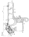
- FIG.1 is a cross-sectional side view showing preferred embodiment of a supercharged pressure control apparatus in accordance with the present invention.
- FIG.2 is a cross-sectional side view showing another preferred embodiment of a supercharge pressure control valve apparatus in accordance with the present invention.
- FIG.3 is a cross-sectional side view showing the constitution of the conventional supercharged pressure control valve apparatus.
- FIG.1 A first preferred embodiment of a supercharger pressure control valve apparatus in accordance with the present invention is described referring to FIG.1.
- the supercharger pressure control valve apparatus in accordance with the present invention comprises: a housing 101 of a supercharger having therein a first and a second by-pass air paths 103 and 104; a casing 105 fixed on the housing 101 by screws; a valve seat 108 formed at an end of the second by-pass air path 104; a valve disc 122 having a seal part 110 which has a convex section for closing the second by-pass air path 104 by contacting with the valve seat 108; a pipe-shaped holder 111 fixed on the valve disk 122 in the casing 105 for holding the valve disc 122; a pipe- shaped support 120 fixed on the ceiling of the casing 105 and outer surface thereof being slidably coupled with the inner surface of the holder 111 in a manner to make the valve disc 122 slidably move in vertical direction; a compression spring 113 provided between the support 120 and the holder 111; and a nipple 114 connected to a downstream part of a throttle valve
- a bottom hole 121 is formed on the bottom end of the support 120 and the top end of a center shaft 123 of the valve disc 122 has a wedge-shaped snap-fit part 123a.
- the shaft 123 loosely couples with the hole 121 of the support 120.
- a diaphragm 124 is integrated with the valve disc 122 by baking treatment. Outer periphery 124a of the diaphragm 124 is made thick and has convex and concave section and it is directly sandwiched by the casing 105 and the housing 101.
- the outer periphery 124a of the diaphragm 124 seals the gap between the casing 105 and the housing 101, thereby the conventional seal member 23c shown in FIG.3 is not necessary. Furthermore, the shaft 123 of the valve disc 122 involves with the hook part 121 of the support 120. so that the seal part 110 of the diaphragm 124 may not fall out from the valve seat 108.
- FIG.2 Another preferred embodiment of the supercharger pressure control valve apparatus is described referring to FIG.2.
- a supercharger pressure control valve apparatus is integrated in a supercharger.
- a housing 31 of the supercharger has an air suction path 33 in which the sucked air passes, a first and a second by-pass ways 34 and 35.
- a fan 32 is rotatably born in a room 31a of the housing 31.
- a casing 36 is fixed on the housing 31 by screw 37; a diaphragm 38 made of rubber has a thick convex and concave section at its outer periphery 38a, which is fixed by sandwiching between the casing 36 and the housing 31 for sealing a gap therebetween.
- a valve seat 39 is formed on an end of the second by-pass air path 35.
- the valve seat 39 and a mounting surface 31b of the housing 31, on which the diaphragm 38 is mounted, are formed on the same plane.
- a valve disc 40 made of resin is baked so as to be integrated with the diaphragm 38.
- a sealing part 41 of the valve disc 40 touches the valve seat 39 for closing the second by-pass air path 35.
- a spring 42 is provided between a support 43 and a holder 44 in the casing 36.
- a nipple 45 is formed on the upper part of the casing 36 connected to downstream part 34b of a throttle valve 6 which is provided, for example, in the first by-pass air path 34 for introducing the supercharged air in the first by-pass air path 34 to a pressure chamber 36a in the casing 36 by a path 20.
- the throttle valve 6 is substantially fully opened. Pressures in both of an air suction path on the downstream part 34b of the throttle valve 6 and the first by-pass air path 34 are highly pressed due to the supercharging effect of the fan 32 of the super-charger. The pressures in both sides of the diaphragm 38 are the same and positive pressures. As a result, a force in a direction to close the valve disc 40 by the spring 42 is applied to the diaphragm 38 and the valve disc 40 is completely closed by contacting of the sealing part 41 with the valve seat 39.
- the outer periphery of the diaphragm made of rubber and having thick convex and concave section 124 or 38 is directly sandwiched by the housing 101 or 31 and the casing 105 or 36.
- the conventional sealing member is omitted, and the numbers of the parts constituting the apparatus is reduced and the workability to assemble the apparatus is improved.
- the conventional pipes for connecting the supercharger and the supercharger pressure control valve are not necessary any more. Therefore, the space necessary for the apparatus is to be provided decreases and the cost to make the apparatus is reduced.
- the part where the diaphragm 124 or 38 is fixed and the part of the valve seat 108 or 39 of the housing 101 or 31 are on the same plane, the cost to make the housing 101 or 31 low and the work to assemble the supercharger pressure control valve on the supercharger is easy.
Landscapes
- Engineering & Computer Science (AREA)
- Mechanical Engineering (AREA)
- General Engineering & Computer Science (AREA)
- Chemical & Material Sciences (AREA)
- Combustion & Propulsion (AREA)
- Life Sciences & Earth Sciences (AREA)
- Sustainable Development (AREA)
- Supercharger (AREA)
- Fluid-Driven Valves (AREA)
- Safety Valves (AREA)
Description
- The present invention relates to a supercharger pressure control valve apparatus according to the preamble of
claim 1, for regulating abnormal pressure rise in the upstream part of an air suction path of a throttle valve, which may occur at closing the throttle valve for deceleration. - The EP-
A-0 123 515 discloses a supercharger pressure control valve apparatus, comprising a housing having a pressure side air path and a suction side air path of a supercharger therein, a casing fixed on the housing, a diaphragm, the outer periphery of which is sandwiched between the casing and the housing, and a valve disc fixed to the diaphragm, circulation of supercharged air between said pressure side air path and suction side air path being permitted by movement of said diaphragm against a biasing spring. - The said diaphragm comprises a sealing part having a convex section for closing the connection between said suction side air path and said pressure side air path by contacting with a valve seat of the housing arranged around said pressure side air path. The said valve seat and the mounting surface of the housing, on which the outer periphery of the diaphragm is mounted, are formed on different planes, i. e. at different levels. Therefore, the cost for making the known apparatus is relatively high; above all in view of the fact that the plane comprising the valve seat and the said mounting surface have to be made in a precise correlation to each other.
- Another conventional supercharger pressure control valve apparatus to be used in an internal combustion engine as, for example, shown in Published Unexamined Japanese Utility Model Application Hei 1-58723, will be described now with reference to FIG. 3. FIG. 3 is a cross-sectional view showing the said conventional supercharger pressure control valve apparatus. In FIG. 3, the conventional supercharger pressure control valve apparatus comprises: an
air cleaner 1 serving as an air sucking portion;suction pipes air cleaner 1; asupercharger 3 connected to thesuction pipes throttle valve 6 for controlling the amount of the suction air; adecompression path 8; and a superchargerpressure control valve 9. In thesuction pipe 2, the upstream part 4 of thesupercharger 3 is a first suction air path and thedownstream part 5 of thesupercharger 3 is a second suction air path. Thedecompression path 8 connects the first and secondsuction air paths 4 and 5. The superchargerpressure control valve 9 controls the pressure of the supercharged pressure in the secondsuction air path 5 by opening and closing thedecompression path 8. - Details of the supercharger
pressure control valve 9 are described. The superchargerpressure control valve 9 comprises: acylindrical housing 10; a second path formed in a wall part of thehousing 10 for introducing the supercharged air in the secondsuction air path 5 to asecond pressure chamber 29; and aflange 13 formed on the lower end of thehousing 10 and mounted on amounting part 14 of thesuction pipe 2 serving as the secondsuction air path 5. Furthermore, avalve seat 15 is formed on an inner wall of thehousing 10 and around an opening 13a of theflange 13. Anipple part 16 of thehousing 10 serving as an inlet and an outlet of the suction air is connected to thesuction pipe 2 serving as the first suction air path 4. A disc-shaped diaphragm 17 is sealed at its outer periphery by a cup-shaped casing 18 and circular periphery of top end of thehousing 10. Afirst pressure chamber 1 is formed by thediaphragm 17 and thecasing 18. Afirst path 20 connects anoutput port 21 and anipple 22 for introducing the supercharged air in a third suction air path 7 to thefirst pressure chamber 19. Plate-shaped holders diaphragm 17, and an end of arod 24 is connected at the center of theholders valve disc 25 for opening and closing thedecompression path 8 is connected to the other end of therod 24 and formed to contact with thevalve seat 15. Therod 24 is slidably born by abearing 26 and thebearing 26 is supported by abearing holder 27. Aspring 28 is compressedly provided between thecasing 18 and theholder 23a for supplying an elastic force to the inside bottom of thediaphragm 17 in a direction to close thevalve 9. Thesecond pressure chamber 29 is formed between thediaphragm 17 and thebearing holder 27 and connected to the secondsuction air path 5 by thesecond path 11. Athrottle 30 is formed in thesecond path 11 which serves as an air resistance for making a transfer lag of the pressure in thesecond path 11. - In the above-mentioned conventional supercharger pressure control valve apparatus, a
seal member 23c is necessary to keep the sealing of thecasing 18 and thehousing 10. Thereby, number of the parts and components for constituting the apparatus is great and the workability to assemble thecasing 18 on thehousing 10 is not good. Furthermore, thesupercharger 3 and the superchargerpressure control valve 9 are independently disposed and connected by thesuction pipe 2. As a result, a large space is necessary to provide the conventional apparatus. Still more, the conventional apparatus needs plural pipes for making the by-pass air path (decompression path 8) and thereby, the cost for making the conventional apparatus is expensive. - The purpose of the present invention is to provide an improved supercharger pressure control valve apparatus, in which the size thereof is made small and the cost for making the apparatus is reduced.
- The said object of the invention is achieved by the characterizing features of
claim 1 in combination with the features of its preamble. - Preferred embodiments and structural details of the present invention are described in the subsidiary claims, and with reference to the enclosed drawings.
- FIG.1 is a cross-sectional side view showing preferred embodiment of a supercharged pressure control apparatus in accordance with the present invention.
- FIG.2 is a cross-sectional side view showing another preferred embodiment of a supercharge pressure control valve apparatus in accordance with the present invention.
- FIG.3 is a cross-sectional side view showing the constitution of the conventional supercharged pressure control valve apparatus.
- A first preferred embodiment of a supercharger pressure control valve apparatus in accordance with the present invention is described referring to FIG.1.
- In FIG.1, the supercharger pressure control valve apparatus in accordance with the present invention comprises: a
housing 101 of a supercharger having therein a first and a second by-pass air paths casing 105 fixed on thehousing 101 by screws; avalve seat 108 formed at an end of the second by-pass air path 104; avalve disc 122 having aseal part 110 which has a convex section for closing the second by-pass air path 104 by contacting with thevalve seat 108; a pipe-shaped holder 111 fixed on thevalve disk 122 in thecasing 105 for holding thevalve disc 122; a pipe-shaped support 120 fixed on the ceiling of thecasing 105 and outer surface thereof being slidably coupled with the inner surface of theholder 111 in a manner to make thevalve disc 122 slidably move in vertical direction; acompression spring 113 provided between thesupport 120 and theholder 111; and anipple 114 connected to a downstream part of a throttle valve which is provided in, for example, the first by-pass air path 103 in vertically lower position of the apparatus (not shown in the figure because of obvious). When thevalve disk 122 is moved in upper direction against the elastic force of thespring 113, the first by-pass air path 103 and the second by-pass air path 104 are connected to be passed by an air current. - A
bottom hole 121 is formed on the bottom end of thesupport 120 and the top end of acenter shaft 123 of thevalve disc 122 has a wedge-shaped snap-fit part 123a. Theshaft 123 loosely couples with thehole 121 of thesupport 120. Adiaphragm 124 is integrated with thevalve disc 122 by baking treatment.Outer periphery 124a of thediaphragm 124 is made thick and has convex and concave section and it is directly sandwiched by thecasing 105 and thehousing 101. - In the above-mentioned supercharger pressure control valve apparatus, the
outer periphery 124a of thediaphragm 124 seals the gap between thecasing 105 and thehousing 101, thereby theconventional seal member 23c shown in FIG.3 is not necessary. Furthermore, theshaft 123 of thevalve disc 122 involves with thehook part 121 of thesupport 120. so that theseal part 110 of thediaphragm 124 may not fall out from thevalve seat 108. - Another preferred embodiment of the supercharger pressure control valve apparatus is described referring to FIG.2. In this embodiment, a supercharger pressure control valve apparatus is integrated in a supercharger.
- In FIG.2, a
housing 31 of the supercharger has anair suction path 33 in which the sucked air passes, a first and a second by-pass ways fan 32 is rotatably born in aroom 31a of thehousing 31. - In the supercharger pressure control valve apparatus, a
casing 36 is fixed on thehousing 31 byscrew 37; adiaphragm 38 made of rubber has a thick convex and concave section at itsouter periphery 38a, which is fixed by sandwiching between thecasing 36 and thehousing 31 for sealing a gap therebetween. Avalve seat 39 is formed on an end of the second by-pass air path 35. Thevalve seat 39 and amounting surface 31b of thehousing 31, on which thediaphragm 38 is mounted, are formed on the same plane. - A
valve disc 40 made of resin is baked so as to be integrated with thediaphragm 38. A sealingpart 41 of thevalve disc 40 touches thevalve seat 39 for closing the second by-pass air path 35. Aspring 42 is provided between asupport 43 and aholder 44 in thecasing 36. A nipple 45 is formed on the upper part of thecasing 36 connected todownstream part 34b of athrottle valve 6 which is provided, for example, in the first by-pass air path 34 for introducing the supercharged air in the first by-pass air path 34 to apressure chamber 36a in thecasing 36 by apath 20. - Operations of the above-mentioned embodiment of the supercharger pressure control valve apparatus in accordance with the present invention is described. For medium load driving or heavy load driving of an automobile, the
throttle valve 6 is substantially fully opened. Pressures in both of an air suction path on thedownstream part 34b of thethrottle valve 6 and the first by-pass air path 34 are highly pressed due to the supercharging effect of thefan 32 of the super-charger. The pressures in both sides of thediaphragm 38 are the same and positive pressures. As a result, a force in a direction to close thevalve disc 40 by thespring 42 is applied to thediaphragm 38 and thevalve disc 40 is completely closed by contacting of the sealingpart 41 with thevalve seat 39. - When the state of the automobile engine is changed to the deceleration driving in which the
throttle valve 6 is suddenly closed from the above-mentioned medium load driving or heavy load driving, the pressure in thedownstream part 34b of air suction path of thethrottle valve 6 is changed to a negative high pressure and that in thecasing 36 also changes to a great negative high pressure. The pressure in the first by-pass air path 34 is raised to a high positive pressure so far as thefan 32 rotates. As a result, thevalve disc 40 is opened against the force of thespring 42 and the supercharged air circulates in the first and second by-pass air paths upstream part 34a of thethrottle valve 6 is prevented. - As mentioned above, in the supercharger pressure control valve apparatus in accordance with the present invention, the outer periphery of the diaphragm made of rubber and having thick convex and
concave section housing casing - Furthermore, since the supercharger and the supercharger pressure control valve are integrated in one body, the conventional pipes for connecting the supercharger and the supercharger pressure control valve are not necessary any more. Thereby, the space necessary for the apparatus is to be provided decreases and the cost to make the apparatus is reduced.
- Still furthermore, since the part where the
diaphragm valve seat housing housing
Claims (6)
- A supercharger pressure control valve apparatus,
comprising a housing (31, 101) having a pressure side air path (34, 103) and a suction side air path (35, 104) of a supercharger therein, a casing (36, 105) fixed on the housing (31, 101), a diaphragm (38, 124), the outer periphery (38a, 124a) of which is sandwiched between the casing (36, 105) and the housing (31, 101), and a valve disc (40, 122) fixed to the diaphragm (38, 124),
circulation of supercharged air between said pressure side air path (34, 103) and suction side air path (35, 104) being permitted by movement of said diaphragm (38, 124) against a biasing spring (42, 113),
characterized in that
said valve disc (40, 122) comprises a sealing part (41, 110) which has a convex section for closing the connection between said suction side air path (35, 104) and said pressure side air path (34, 103) by contacting with a valve seat (39, 108) of the housing (31, 101) arranged around said suction side air path (35, 104), and
said valve seat (39, 108) and the mounting surface (31b) of the housing (31, 101), on which the outer periphery (38a, 124a) of the diaphragm (38, 124) is mounted, are formed on the same plane. - Apparatus according to claim 1, wherein said valve disc (40, 122) is integrated with said diaphragm (38, 124) by baking treatment.
- Apparatus according to claim 1 or 2, wherein a pipe-shaped holder (44, 111) is fixed on the valve disc (40, 122) in the casing (36, 105) for holding the valve disc (40, 122) while a pipe-shaped support (43, 120) is fixed on the ceiling of the casing (36, 105), the outer surface of said support (43, 120) being slidably coupled with the inner surface of said holder (44, 111) so as to make the valve disc (40, 122) slidably move in vertical direction.
- Apparatus according to claim 3, wherein said valve disc (40, 122) comprises a center shaft (123), the top end of which has a wedge-shaped snap-fit part (123a), loosely coupled with a bottom hole (121) formed on the bottom end of the support (120).
- Apparatus according to claim 1, wherein a fan (32) of the supercharger is rotatably contained in a room (31a) formed in the housing (31, 101).
- Apparatus according to claim 1, wherein the diaphragm (38, 124) is made of rubber, having a thick convex and concave section at the outer periphery (38a, 124a) thereof which is fixed by being sandwiched between the casing (36, 105) and the housing (31, 101) for sealing a gap therebetween.
Applications Claiming Priority (6)
| Application Number | Priority Date | Filing Date | Title |
|---|---|---|---|
| JP1127151A JPH02305323A (en) | 1989-05-19 | 1989-05-19 | Supercharging pressure control valve device |
| JP1127152A JPH086601B2 (en) | 1989-05-19 | 1989-05-19 | Boost pressure control valve device |
| JP127151/89 | 1989-05-19 | ||
| JP127152/89 | 1989-05-19 | ||
| JP20312789A JPH0366984A (en) | 1989-08-05 | 1989-08-05 | Valve device |
| JP203127/89 | 1989-08-05 |
Publications (3)
| Publication Number | Publication Date |
|---|---|
| EP0398379A2 EP0398379A2 (en) | 1990-11-22 |
| EP0398379A3 EP0398379A3 (en) | 1991-01-23 |
| EP0398379B1 true EP0398379B1 (en) | 1993-12-22 |
Family
ID=27315473
Family Applications (1)
| Application Number | Title | Priority Date | Filing Date |
|---|---|---|---|
| EP19900109544 Expired - Lifetime EP0398379B1 (en) | 1989-05-19 | 1990-05-18 | Supercharged pressure control valve apparatus |
Country Status (3)
| Country | Link |
|---|---|
| US (1) | US5137003A (en) |
| EP (1) | EP0398379B1 (en) |
| DE (2) | DE398379T1 (en) |
Families Citing this family (29)
| Publication number | Priority date | Publication date | Assignee | Title |
|---|---|---|---|---|
| US5277029A (en) * | 1991-06-18 | 1994-01-11 | Toyota Jidosha Kabushiki Kaisha | Internal combustion engine with a dual turbocharger system |
| JP3494773B2 (en) * | 1995-09-27 | 2004-02-09 | 三菱電機株式会社 | Supercharging pressure control device |
| DE19637055A1 (en) * | 1996-09-12 | 1998-03-19 | Bosch Gmbh Robert | Valve for an internal combustion engine and internal combustion engine |
| US6325097B1 (en) * | 1997-01-31 | 2001-12-04 | Hill-Rom Services, Inc. | Manifold and regulator apparatus |
| US6164269A (en) * | 1997-10-31 | 2000-12-26 | Caterpillar Inc. | Exhaust gas recirculation valve assembly having an integrated check valve |
| SE521795C2 (en) | 1999-05-10 | 2003-12-09 | Volvo Lastvagnar Ab | valve device |
| US6269805B1 (en) | 2000-02-15 | 2001-08-07 | Keith Wilson | Manifold spacer |
| DE10251981A1 (en) * | 2002-11-08 | 2005-03-03 | Pierburg Gmbh | Impulse air valve device for a turbo-charged combustion engine is controlled by connection of its control pressure chamber to the pressure side of the bypass line of the supercharger pump |
| CN100567715C (en) * | 2003-10-20 | 2009-12-09 | 霍尼韦尔国际公司 | Adjustable valves, especially recirculation valves for turbochargers |
| JP4495120B2 (en) * | 2006-08-10 | 2010-06-30 | 三菱重工業株式会社 | Multistage turbocharged turbocharger |
| WO2008055588A1 (en) * | 2006-11-09 | 2008-05-15 | Borgwarner Inc. | Turbocharger |
| JP2009236147A (en) * | 2008-03-26 | 2009-10-15 | Fuji Koki Corp | Pressure control valve |
| DE102009032685B4 (en) * | 2009-07-09 | 2012-12-06 | Eagle Actuator Components Gmbh & Co. Kg | Pre-assembled valve assembly for use in a turbocharger |
| US8539769B2 (en) * | 2009-10-14 | 2013-09-24 | Craig N. Hansen | Internal combustion engine and supercharger |
| DE202009013401U1 (en) | 2009-10-22 | 2010-07-29 | Woco Industrietechnik Gmbh | Diverter valve |
| DE102010005826A1 (en) * | 2010-01-27 | 2011-07-28 | GM Global Technology Operations LLC, ( n. d. Ges. d. Staates Delaware ), Mich. | Suction pipe module for turbo engine, particularly turbo engine according to Otto principle, for motor vehicle, has suction pipe and control valve that is designed as three-way valve and is connected to suction pipe by attachment |
| CN102782282B (en) | 2010-03-18 | 2016-01-27 | 三菱电机株式会社 | Air by-pass control valve unit |
| DE102010013264A1 (en) | 2010-03-29 | 2011-09-29 | Continental Automotive Gmbh | Turbocharger housing with a valve device and method for producing such a turbocharger housing |
| US9091232B2 (en) * | 2010-09-02 | 2015-07-28 | Borgwarner Inc. | Compressor recirculation into annular volume |
| KR101209727B1 (en) * | 2010-09-29 | 2012-12-07 | 현대자동차주식회사 | Turbo chrager having anti-surge valve |
| DE102010050669A1 (en) * | 2010-11-09 | 2012-05-10 | Voith Patent Gmbh | Housing for an impeller |
| JP2012241558A (en) * | 2011-05-17 | 2012-12-10 | Ihi Corp | Bypass valve and supercharger |
| DE102011052132C5 (en) * | 2011-07-26 | 2020-07-23 | Woco Industrietechnik Gmbh | Diverter valve |
| KR20140046285A (en) * | 2012-10-10 | 2014-04-18 | 현대자동차주식회사 | Anti-surge valve for vehicle |
| US20140166130A1 (en) * | 2012-12-17 | 2014-06-19 | Kia Motors Corporation | Anti-surge valve |
| DE102012025411A1 (en) * | 2012-12-20 | 2014-07-10 | Borgwarner Inc. | Recirculation valve of an exhaust gas turbocharger compressor |
| JP2016113965A (en) * | 2014-12-15 | 2016-06-23 | 京三電機株式会社 | Valve device of fuel steam system |
| DE112015006087T5 (en) | 2015-01-29 | 2017-10-12 | Ihi Corporation | TURBOCHARGER |
| WO2020008615A1 (en) * | 2018-07-06 | 2020-01-09 | 三菱重工エンジン&ターボチャージャ株式会社 | Centrifugal compressor and turbocharger |
Family Cites Families (5)
| Publication number | Priority date | Publication date | Assignee | Title |
|---|---|---|---|---|
| DE2313734A1 (en) * | 1973-03-20 | 1974-10-03 | Hans Sasserath & Co Kg Rheydt | FITTINGS FOR SHUT-OFF OF A PIPE DEPENDING ON THE FLOW |
| US4493339A (en) * | 1982-05-05 | 1985-01-15 | Porter Instrument Company, Inc. | Air valve for a breathing system |
| DE3236564A1 (en) * | 1982-10-02 | 1984-04-05 | Bayerische Motoren Werke AG, 8000 München | BLOW-OFF DEVICE FOR CHARGED INTERNAL COMBUSTION ENGINES, WITH A BLOW-OFF VALVE ARRANGED ON THE AIR SIDE |
| US4517803A (en) * | 1983-04-22 | 1985-05-21 | The Garrett Corporation | Turbocharger compressor valve |
| JPS6458723A (en) * | 1987-08-27 | 1989-03-06 | Yoshio Murahashi | Lower dam type intake method |
-
1990
- 1990-05-15 US US07/523,531 patent/US5137003A/en not_active Expired - Lifetime
- 1990-05-18 EP EP19900109544 patent/EP0398379B1/en not_active Expired - Lifetime
- 1990-05-18 DE DE199090109544T patent/DE398379T1/en active Pending
- 1990-05-19 DE DE69005357T patent/DE69005357T2/en not_active Expired - Lifetime
Also Published As
| Publication number | Publication date |
|---|---|
| US5137003A (en) | 1992-08-11 |
| EP0398379A2 (en) | 1990-11-22 |
| EP0398379A3 (en) | 1991-01-23 |
| DE69005357D1 (en) | 1994-02-03 |
| DE398379T1 (en) | 1991-05-23 |
| DE69005357T2 (en) | 1994-05-26 |
Similar Documents
| Publication | Publication Date | Title |
|---|---|---|
| US5137003A (en) | Supercharged pressure control valve apparatus | |
| US3739797A (en) | Control apparatus for exhaust gas recirculating system | |
| US4517803A (en) | Turbocharger compressor valve | |
| US5090393A (en) | Pressure regulating valve for installation in a vent duct of an internal combustion engine | |
| US4763636A (en) | Mechanical supercharger | |
| US4484445A (en) | Arrangement for controlling exhaust gas recirculation in a supercharged internal combustion engine | |
| JPH02305324A (en) | Supercharging pressure control valve device | |
| US5571264A (en) | Fluid sealed type antivibration rubber device | |
| DE3363618D1 (en) | Three-ports-two-positions valve | |
| JPH03151558A (en) | Control device of exhaust gas reflux rate in internal combustion engine | |
| US4365608A (en) | Controlling engine exhaust gas recirculation and vacuum inverter | |
| JP2000227050A (en) | Exhaust gas recirculation valve device | |
| JPH02305323A (en) | Supercharging pressure control valve device | |
| JPS5924804Y2 (en) | Secondary air supply device | |
| JPH02286974A (en) | Valve device | |
| JPH0366984A (en) | Valve device | |
| US4633845A (en) | Vacuum control device | |
| JPS6133250Y2 (en) | ||
| JPS6146201Y2 (en) | ||
| JP2780758B2 (en) | Supercharging pressure control valve device | |
| JPS6221191Y2 (en) | ||
| JPS6212949Y2 (en) | ||
| JPH0619783Y2 (en) | Blow-by gas recirculation system for engines | |
| JPH0788815B2 (en) | Diaphragm type vacuum pump | |
| JPH0211903A (en) | Pressure fitting structure |
Legal Events
| Date | Code | Title | Description |
|---|---|---|---|
| PUAI | Public reference made under article 153(3) epc to a published international application that has entered the european phase |
Free format text: ORIGINAL CODE: 0009012 |
|
| 17P | Request for examination filed |
Effective date: 19900519 |
|
| AK | Designated contracting states |
Kind code of ref document: A2 Designated state(s): DE FR |
|
| PUAL | Search report despatched |
Free format text: ORIGINAL CODE: 0009013 |
|
| AK | Designated contracting states |
Kind code of ref document: A3 Designated state(s): DE FR |
|
| EL | Fr: translation of claims filed | ||
| DET | De: translation of patent claims | ||
| 17Q | First examination report despatched |
Effective date: 19920629 |
|
| GRAA | (expected) grant |
Free format text: ORIGINAL CODE: 0009210 |
|
| AK | Designated contracting states |
Kind code of ref document: B1 Designated state(s): DE FR |
|
| REF | Corresponds to: |
Ref document number: 69005357 Country of ref document: DE Date of ref document: 19940203 |
|
| ET | Fr: translation filed | ||
| PLBE | No opposition filed within time limit |
Free format text: ORIGINAL CODE: 0009261 |
|
| STAA | Information on the status of an ep patent application or granted ep patent |
Free format text: STATUS: NO OPPOSITION FILED WITHIN TIME LIMIT |
|
| 26N | No opposition filed | ||
| PGFP | Annual fee paid to national office [announced via postgrant information from national office to epo] |
Ref country code: DE Payment date: 20090514 Year of fee payment: 20 Ref country code: FR Payment date: 20090515 Year of fee payment: 20 |
|
| PG25 | Lapsed in a contracting state [announced via postgrant information from national office to epo] |
Ref country code: DE Free format text: LAPSE BECAUSE OF EXPIRATION OF PROTECTION Effective date: 20100518 |