EP0398352A2 - An automatic engraving system - Google Patents
An automatic engraving system Download PDFInfo
- Publication number
- EP0398352A2 EP0398352A2 EP90109454A EP90109454A EP0398352A2 EP 0398352 A2 EP0398352 A2 EP 0398352A2 EP 90109454 A EP90109454 A EP 90109454A EP 90109454 A EP90109454 A EP 90109454A EP 0398352 A2 EP0398352 A2 EP 0398352A2
- Authority
- EP
- European Patent Office
- Prior art keywords
- contour
- person
- engraving
- medals
- light beam
- Prior art date
- Legal status (The legal status is an assumption and is not a legal conclusion. Google has not performed a legal analysis and makes no representation as to the accuracy of the status listed.)
- Granted
Links
Images


Classifications
-
- B—PERFORMING OPERATIONS; TRANSPORTING
- B44—DECORATIVE ARTS
- B44B—MACHINES, APPARATUS OR TOOLS FOR ARTISTIC WORK, e.g. FOR SCULPTURING, GUILLOCHING, CARVING, BRANDING, INLAYING
- B44B1/00—Artist's machines or apparatus equipped with tools or work holders moving or able to be controlled three-dimensionally for making single sculptures or models
- B44B1/006—Artist's machines or apparatus equipped with tools or work holders moving or able to be controlled three-dimensionally for making single sculptures or models using computer control means
-
- B—PERFORMING OPERATIONS; TRANSPORTING
- B44—DECORATIVE ARTS
- B44B—MACHINES, APPARATUS OR TOOLS FOR ARTISTIC WORK, e.g. FOR SCULPTURING, GUILLOCHING, CARVING, BRANDING, INLAYING
- B44B1/00—Artist's machines or apparatus equipped with tools or work holders moving or able to be controlled three-dimensionally for making single sculptures or models
- B44B1/02—Artist's machines or apparatus equipped with tools or work holders moving or able to be controlled three-dimensionally for making single sculptures or models wherein three-dimensional copies are made
- B44B1/04—Artist's machines or apparatus equipped with tools or work holders moving or able to be controlled three-dimensionally for making single sculptures or models wherein three-dimensional copies are made having devices for changing, e.g. proportionally enlarging or reducing, the shape from an original pattern
-
- B—PERFORMING OPERATIONS; TRANSPORTING
- B44—DECORATIVE ARTS
- B44C—PRODUCING DECORATIVE EFFECTS; MOSAICS; TARSIA WORK; PAPERHANGING
- B44C1/00—Processes, not specifically provided for elsewhere, for producing decorative surface effects
- B44C1/22—Removing surface-material, e.g. by engraving, by etching
- B44C1/222—Removing surface-material, e.g. by engraving, by etching using machine-driven mechanical means
-
- B—PERFORMING OPERATIONS; TRANSPORTING
- B44—DECORATIVE ARTS
- B44C—PRODUCING DECORATIVE EFFECTS; MOSAICS; TARSIA WORK; PAPERHANGING
- B44C1/00—Processes, not specifically provided for elsewhere, for producing decorative surface effects
- B44C1/22—Removing surface-material, e.g. by engraving, by etching
- B44C1/225—Removing surface-material, e.g. by engraving, by etching by engraving
-
- G—PHYSICS
- G05—CONTROLLING; REGULATING
- G05B—CONTROL OR REGULATING SYSTEMS IN GENERAL; FUNCTIONAL ELEMENTS OF SUCH SYSTEMS; MONITORING OR TESTING ARRANGEMENTS FOR SUCH SYSTEMS OR ELEMENTS
- G05B19/00—Programme-control systems
- G05B19/02—Programme-control systems electric
- G05B19/42—Recording and playback systems, i.e. in which the programme is recorded from a cycle of operations, e.g. the cycle of operations being manually controlled, after which this record is played back on the same machine
- G05B19/4202—Recording and playback systems, i.e. in which the programme is recorded from a cycle of operations, e.g. the cycle of operations being manually controlled, after which this record is played back on the same machine preparation of the programme medium using a drawing, a model
- G05B19/4207—Recording and playback systems, i.e. in which the programme is recorded from a cycle of operations, e.g. the cycle of operations being manually controlled, after which this record is played back on the same machine preparation of the programme medium using a drawing, a model in which a model is traced or scanned and corresponding data recorded
-
- G—PHYSICS
- G05—CONTROLLING; REGULATING
- G05B—CONTROL OR REGULATING SYSTEMS IN GENERAL; FUNCTIONAL ELEMENTS OF SUCH SYSTEMS; MONITORING OR TESTING ARRANGEMENTS FOR SUCH SYSTEMS OR ELEMENTS
- G05B2219/00—Program-control systems
- G05B2219/30—Nc systems
- G05B2219/37—Measurements
- G05B2219/37275—Laser, interferometer
-
- G—PHYSICS
- G05—CONTROLLING; REGULATING
- G05B—CONTROL OR REGULATING SYSTEMS IN GENERAL; FUNCTIONAL ELEMENTS OF SUCH SYSTEMS; MONITORING OR TESTING ARRANGEMENTS FOR SUCH SYSTEMS OR ELEMENTS
- G05B2219/00—Program-control systems
- G05B2219/30—Nc systems
- G05B2219/37—Measurements
- G05B2219/37563—Ccd, tv camera
-
- G—PHYSICS
- G05—CONTROLLING; REGULATING
- G05B—CONTROL OR REGULATING SYSTEMS IN GENERAL; FUNCTIONAL ELEMENTS OF SUCH SYSTEMS; MONITORING OR TESTING ARRANGEMENTS FOR SUCH SYSTEMS OR ELEMENTS
- G05B2219/00—Program-control systems
- G05B2219/30—Nc systems
- G05B2219/37—Measurements
- G05B2219/37567—3-D vision, stereo vision, with two cameras
-
- G—PHYSICS
- G05—CONTROLLING; REGULATING
- G05B—CONTROL OR REGULATING SYSTEMS IN GENERAL; FUNCTIONAL ELEMENTS OF SUCH SYSTEMS; MONITORING OR TESTING ARRANGEMENTS FOR SUCH SYSTEMS OR ELEMENTS
- G05B2219/00—Program-control systems
- G05B2219/30—Nc systems
- G05B2219/45—Nc applications
- G05B2219/45212—Etching, engraving, sculpturing, carving
-
- G—PHYSICS
- G05—CONTROLLING; REGULATING
- G05B—CONTROL OR REGULATING SYSTEMS IN GENERAL; FUNCTIONAL ELEMENTS OF SUCH SYSTEMS; MONITORING OR TESTING ARRANGEMENTS FOR SUCH SYSTEMS OR ELEMENTS
- G05B2219/00—Program-control systems
- G05B2219/30—Nc systems
- G05B2219/50—Machine tool, machine tool null till machine tool work handling
- G05B2219/50247—Change to finer, more adapted tools to machine complex surface
-
- Y—GENERAL TAGGING OF NEW TECHNOLOGICAL DEVELOPMENTS; GENERAL TAGGING OF CROSS-SECTIONAL TECHNOLOGIES SPANNING OVER SEVERAL SECTIONS OF THE IPC; TECHNICAL SUBJECTS COVERED BY FORMER USPC CROSS-REFERENCE ART COLLECTIONS [XRACs] AND DIGESTS
- Y10—TECHNICAL SUBJECTS COVERED BY FORMER USPC
- Y10T—TECHNICAL SUBJECTS COVERED BY FORMER US CLASSIFICATION
- Y10T409/00—Gear cutting, milling, or planing
- Y10T409/30—Milling
- Y10T409/30084—Milling with regulation of operation by templet, card, or other replaceable information supply
- Y10T409/301176—Reproducing means
- Y10T409/301624—Duplicating means
- Y10T409/30168—Duplicating means with means for operation without manual intervention
- Y10T409/301792—Duplicating means with means for operation without manual intervention including means to sense optical or magnetic image
Definitions
- the present invention relates generally to an automatic engraving system. More particularly, the present invention relates to a system for automatically engraving the contour of a person's face as seen in the lateral direction on one surface of a medal as a raw material within a short period of time.
- the above-described conventional method is preferably employable for producing a number of medals each having a same design on a mass production line.
- the conventional method fails to effectively produce a medal one by one of which one surface is engraved with a specific design.
- medal vending machines are installed on an exhibition ground or the like place where many persons get together. Each of medals received from the vending machine by putting a certain value of coins in a coin collector is previously embossed with a specific image indicative of a monument or a famous great man.
- a stamping machine is installed to stamp a date, a name, a location or the like on a blank space of the coin, as required.
- items to be stamped on the coil are limited only to a vendee's name, a date, characters or the like item but a specific design required by the vendee can not be engraved on the coin any longer.
- the present invention has been made with the foregoing background in mind and its object resides in providing a system for automatically engraving medals each having the contour of a person's face as seen in the lateral direction in a certain location at a certain time on one surface thereof within a short period of time by his request.
- the present invention provides a system for automatically engraving medals each having the contour of a person's face as seen in the lateral direction on one surface thereof, wherein the system includes as essential components three-dimensional contour measuring means for three-dimensionally measuring the lateral contour of the person's face by using light beam or laser light beam, a computor for processing the dimensional data derived from the three-dimensional contour measuring means to determine the lateral contour of the person's face, and at least one three-dimensional cutting machine for engraving the lateral contour of the person's face on one surface of a medal as a raw material based on the processed data derived from the computor.
- the system includes as essential components three-dimensional contour measuring means for three-dimensionally measuring the lateral contour of the person's face by using light beam or laser light beam, a computor for processing the dimensional data derived from the three-dimensional contour measuring means to determine the lateral contour of the person's face, and at least one three-dimensional cutting machine for engraving the lateral contour of the person's face on one
- system further includes monitoring means to assure that the center line of a person sitting on a chair is located in correct alignment with the center line of the monitoring means.
- the three-dimensional contour measuring means comprises two industrial television cameras each disposed at a position offset from the lateral contour of the person's face by a predetermined angle and two charge coupled devices electrically coupled to the two industrial television cameras, each of the charge coupled devices including a monitor screen on which the lateral contour of the person's face is displayed and a number of lattice points being arranged on the monitor screen.
- the lateral contour of the person's face is determined by sequentially measuring a width, a height and a thickness of the lateral contour of the person's face at a certain actual point on the latter and sequentially processing the dimensional data derived from the measurements in the computor.
- each width, each height and each thickness of the lateral contour of the person's face at each actual face are determined based on an angle defined by the actual point on the lateral contour of the person's face relative to the corresponding lattice point on the screen of one charge coupled device electrically coupled to one of the industrial television camera and an angle defined by the actual point on the lateral contour of the person's face relative to the corresponding lattice point on the screen of other charge coupled device electrically coupled to other industrial television camera.
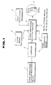
- Fig. 1 is a block diagram which schematically illustrates by way of example structure of an automatic engraving system in accordance with the embodiment of the present invention.
- reference numeral 1 designates adequate three-dimensional contour measuring means for three-dimentionally measuring the contour of an upper half of a sitting lady as seen in the lateral direction by using light beam or laser light beam
- reference numeral 2 designates a computor in the form of a central processing unit (hereinafter referred to as CPU) for calculating a number of dimensional data derived from measurements with the contour measuring means 1 in respect of a width, a length and a thickness of the measured contour of the lady by way of a series of storing, calculating processing and correcting operations
- reference numeral 3 designates a three-dimensional cutting machine for engraving the contour of the lady as seen in the lateral direction on one surface of a medal as a raw material in accordance with the data processed by the CPU 2.
- any conventional machine tool is employable for the three-dimensional cutting machine 3, provided that it is proven that the machine tool can cut the medal 4 by way of several steps.
- the machine 3 is equipped with fixing means 5 in the form of a vice for firmly holding the medal 4, tool exchanging means 6 for sequentially exchanging a plurality of cutting tools, e.g., drill, cutter, end mill or the like tool in accordance with an order preset for engraving operations to be performed for the medal 4 and a dust collector 7 for centrally collecting cut chips.
- the machine 3 may be provided with medal feeding means in which several kinds of medals different from each other in color, size and other factors are previously stored and one medal selected from among the stored metals by request is fed to a cutting location on a table of the machine 3.
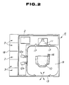
- Figs. 2 and 3 are a view illustrating by way of example concrete structure of the automatic engraving system of the present invention, respectively.
- reference numeral 8 designates a housing for the automatic engraving system for which a plurality of three-dimensional cutting machines 3 (five machines in the shown case) are installed.
- the housing 8 is assembled and firmly installed on a required site, e.g., an exhibition ground, a recreation ground or the like place.
- the housing 8 may be constructed in a portable structure so that it can be placed on an automotive vehicle to freely change its operation site.
- Reference numeral 9 designates an operation booth in the housing 8.
- a chair 10 is arranged at the central part of the booth 9 so that a lady A sits on the chair 10 as a model for engraving operations.
- Reference numeral 11 designates a monitor section which is located in front of the lady A sitting on the chair 10. An image of the lady A is displayed on a screen of the monitor section 11.
- Reference numerals 12a and 12b designates an industrial television camera, respectively. Each of the television cameras 12a and 12b is arranged at a position offset from the sitting lady A by a predetermined angle.
- Reference numeral 13 designates an entrance through which she has entered the booth 9.
- two industrial television cameras 12a and 12b and two charge coupled devices (hereinafter referred to as CCD) 14a and 14b electically coupled to the television cameras 12a and 12b are used for calculating widths X, heights Y and thicknesses Z at a number of positions on the lateral contour of the lady A by using light beam or laser light beam.
- a center line 15 is previously placed on the screen of the monitor 11.
- the lady A should correctly sit on the chair 10 to assume her own position where a center line of her face exactly matches with the center line 15 by watching her image on the monitor 11. Namely, the center line O of her face should be located in correct alignment with the center line 15 on the screen of the monitor 11.
- the chair 10 is turned to the left or right and/or raised up or lowered to adjust its position.
- the monitor 11 may be turned to the left or right and/or raised up or lowered by actuating a suitable mechanism (not shown).
- the contour of the lady A as seen in the lateral direction is displayed on a screen of each of the CCDs 14a and 14b.
- an image on the screen of the CCD (see Fig. 5) is stored in the CPU 2.
- the CPU 2 determines by calculation a series of angles ⁇ 11 to ⁇ nn defined by respective lattice points P (P11, P12, --- , P21 P22, --- , P nn ) on the one CCD 14a relative to respective actual points F (F11, F12, ---, F21, F22, --- , F nn ) on the lateral contour and a series of angles ⁇ 11 to ⁇ nn defined by respective lattice points Q (Q11, Q12, --- , Q21, Q22, --- , Q nn ) on the other CCD 14b relative to the respective actual points F (F11, F12, --- , F21, F22, --- , F nn )
- the CPU 2 determines by calculation an angle ⁇ mm defined by an actual point F mm on the lateral contour relative to a lattice point P mm on the CCD 14a corresponding to the actual point F mm and an angle ⁇ mm defined by the actual point F mm on the lateral contour relative to a lattice point Q mm on the CCD 14b by using light beam or laser light.
- the CPU 2 calculates a distance l mm between the actual point F mm on the lateral contour and each television camera. Since a distance L between the center line 0 of the lateral contour and each TV camera has been previously determined, a thickness Z mm of the lateral contour of the lady A can be calculated by subtracting the distance l mm from the distance L.
- a series of thicknesses Z at respective points on the lateral contour of the lady A are calculated by sequentially performing calculating operations for all the points P11 to P nn and Q11 to Q nn on the CCDs 14a and 14b corresponding to the points F11 to F nn by using light beam or laser light beam.
- the CPU 2 calculates a series of widths X and a series of heights Y at respective points on the lateral contour of the lady A in the same manner as described above, whereby the CPU can determines a whole three-dimensional configuration of the lady A.
- each engraving machines 3 is ready to perform engraving operations on one surface of the medal 4 based on the thus corrected dimensional data.
- the foregoing correction is normally carried out by dividing the respective widths X, the respective heights Y and the respective thicknesses A with a constant rate.
- the present invention should not limited only to this.
- correction may be carried out using different rates. It is preferable that a correction rate for the thicknesses Z is set smaller than those for the widths X and the heights Y.
- the former is set to 1/100, while the latter are set to 1/10, respectively. This is because a medal to be engraved is required to have an excessively heavy thickness, if an engraving operation is to be performed based on the dimensional data on the lateral contour of the lady A which have been derived from the CPU 2 without correction.
- a region on the medal 4 where the engraving operation has been completed is displayed on the screen of the monitor 11 with a different color.
- the present operational step within the range of a single engraving operation may vocally be informed to her via a speaker.
- the automatic engraving system In a case where the automatic engraving system is installed on an exhibition ground or the like place on the commercial basis, it is required that the system is operated at a high efficiency for a possibly long period of time per each day with minimized time loss. To meet the requirement, it is recommendable that the lateral contour displayed on the screen of each CCD 14 is first stored in the CPU 2 and an engraving operation is then performed based on the stored data without necessity for allowing the lady A to continuously stay on the chair 10 till completion of the engraving operation. During the engraving operation, the lady A leaves the booth 9 and another person sits on the chair 10 in place of the lady A. In this case, a receiving port where the engraved medal 4 should be received by the lady A is located outside of the housing 8.
- the machines 3 are successively operated so as to allow a plurality of medals to be successively engraved for many persons without long waiting time.
- a wall 18 located outside of the engraving machines 3 may be made transparent in order that other persons can visually recognize from the outside how far each medal is being engraved.
- the present invention has been described above as to the case where a medal is engraved based on dimensional data on the lateral contour of one person.
- the medal may be engraved based on dimensional data on the contour indicative of an upper half of one person or the whole body of one person as seen from the front side.
- the medal may be engraved based on dimensional data on the contour indicative of plural persons, e.g. a combination of parent and child or children, a couple of young man and woman or a single family.
- the three-dimensional contour measuring means 1 should not be limited only to a combination of the industrial television cameras 14A and 14b and the CCDs 12a and 12b as described above. The following methods may be employed for the three-dimensional contour measuring means 1 which is arranged for the system of the present invention.
- a person's face is scanned by a light beam or laser light beam in the form of a light film which is produced by a parallel light beam enlarging lens system (beam expander) and a composite system comprising a plurality of column-shaped lenses.
- a parallel light beam enlarging lens system beam expander
- a composite system comprising a plurality of column-shaped lenses.
- a Moire equitopographic method is a Moire equitopographic method.
- a lattice having a plurality of slits formed thereon at a constant distance of pitch is arranged in a spaced relationship in front of a person's face and light beam or laser light beam is projected toward the person's face through the slits to form a plurality of light fringes.
- intersections defined by the light fringes and the viewing lines can visually be recognized such that a distance between the lattice surface and the person's face, a lattice pitch and a viewing angle satisfy given conditions.
- a number of intersections continuously appear as the lattice is slidably displaced in the surface between the lattice and the person's face, whereby equialtitude lines are drawn to build an image indicative of the person's face.
- Another method is such that the shadow of a mesh-shaped lattice having a number of lines extending at a right angle is projected on a person's face and the resultant mesh-shaped image is processed by a computor to measure a contour representative of the person's face.
- a holographic interference method wherein deformation and strain are measured can be noted as another available method.
- a system for automatically engraving medals includes as essential components three-dimensional contour measuring means for three-dimensionally measuring the contour of a person as seen in the lateral direction without contact with the person's face by using light beam or laser light beam, a computor for processing dimensional data derived from measurements with the three-dimensional contour measuring means and at least one three-dimensional cutting machine for engraving one surface of a medal based on the thus processed data to reproduce on the medal an image representative of the person's face.
- the system of the present invention assures that a medal having an image dimensionally equal to the person's face can be engraved in the entirely same manner as the conventional image derived from a photographic method.
Abstract
Description
- The present invention relates generally to an automatic engraving system. More particularly, the present invention relates to a system for automatically engraving the contour of a person's face as seen in the lateral direction on one surface of a medal as a raw material within a short period of time.
- Hitherto, when medals each having a certain image indicative of a monument or a famous great man on one surface thereof are produced, a master model is first manually fabricated one by one by a skilled craftsman and then a number of medals are produced on a mass production line using a press die derived from the master model.
- The above-described conventional method is preferably employable for producing a number of medals each having a same design on a mass production line. However, the conventional method fails to effectively produce a medal one by one of which one surface is engraved with a specific design.
- As is well known, medal vending machines are installed on an exhibition ground or the like place where many persons get together. Each of medals received from the vending machine by putting a certain value of coins in a coin collector is previously embossed with a specific image indicative of a monument or a famous great man. In addition, a stamping machine is installed to stamp a date, a name, a location or the like on a blank space of the coin, as required. However, items to be stamped on the coil are limited only to a vendee's name, a date, characters or the like item but a specific design required by the vendee can not be engraved on the coin any longer.
- The present invention has been made with the foregoing background in mind and its object resides in providing a system for automatically engraving medals each having the contour of a person's face as seen in the lateral direction in a certain location at a certain time on one surface thereof within a short period of time by his request.
- To accomplish the above object, the present invention provides a system for automatically engraving medals each having the contour of a person's face as seen in the lateral direction on one surface thereof, wherein the system includes as essential components three-dimensional contour measuring means for three-dimensionally measuring the lateral contour of the person's face by using light beam or laser light beam, a computor for processing the dimensional data derived from the three-dimensional contour measuring means to determine the lateral contour of the person's face, and at least one three-dimensional cutting machine for engraving the lateral contour of the person's face on one surface of a medal as a raw material based on the processed data derived from the computor.
- In addition, the system further includes monitoring means to assure that the center line of a person sitting on a chair is located in correct alignment with the center line of the monitoring means.
- The three-dimensional contour measuring means comprises two industrial television cameras each disposed at a position offset from the lateral contour of the person's face by a predetermined angle and two charge coupled devices electrically coupled to the two industrial television cameras, each of the charge coupled devices including a monitor screen on which the lateral contour of the person's face is displayed and a number of lattice points being arranged on the monitor screen.
- The lateral contour of the person's face is determined by sequentially measuring a width, a height and a thickness of the lateral contour of the person's face at a certain actual point on the latter and sequentially processing the dimensional data derived from the measurements in the computor.
- Then, each width, each height and each thickness of the lateral contour of the person's face at each actual face are determined based on an angle defined by the actual point on the lateral contour of the person's face relative to the corresponding lattice point on the screen of one charge coupled device electrically coupled to one of the industrial television camera and an angle defined by the actual point on the lateral contour of the person's face relative to the corresponding lattice point on the screen of other charge coupled device electrically coupled to other industrial television camera.
- Other objects, features and advantages of the present invention will become more readily apparent from reading of the following description which has been made with reference to the accompanying drawings.
- The present invention is illustrated in the following drawings in which;
- Fig. 1 is a block diagram which schematically illustrates by way of example structure of an automatic engraving system in accordance with an embodiment of the present invention.
- Fig. 2 is a schematic plan view illustrating arrangement of the system in Fig. 1.
- Fig. 3 is a perspective view of the system in Fig. 1.
- Fig. 4 is a schematic plan view illustrating the system of the present invention.
- Fig. 5 is a view illustrating the contour of a lady's face as seen in the lateral direction which appears on the screen of a monitor television for the system of the present invention.
- Now, the present invention will be described in detail hereinafter with reference to the accompanying drawings which illustrate a preferred embodiment thereof.
- Fig. 1 is a block diagram which schematically illustrates by way of example structure of an automatic engraving system in accordance with the embodiment of the present invention. In the drawing, reference numeral 1 designates adequate three-dimensional contour measuring means for three-dimentionally measuring the contour of an upper half of a sitting lady as seen in the lateral direction by using light beam or laser light beam,
reference numeral 2 designates a computor in the form of a central processing unit (hereinafter referred to as CPU) for calculating a number of dimensional data derived from measurements with the contour measuring means 1 in respect of a width, a length and a thickness of the measured contour of the lady by way of a series of storing, calculating processing and correcting operations, andreference numeral 3 designates a three-dimensional cutting machine for engraving the contour of the lady as seen in the lateral direction on one surface of a medal as a raw material in accordance with the data processed by theCPU 2. - Any conventional machine tool is employable for the three-
dimensional cutting machine 3, provided that it is proven that the machine tool can cut themedal 4 by way of several steps. Specifically, themachine 3 is equipped withfixing means 5 in the form of a vice for firmly holding themedal 4, tool exchanging means 6 for sequentially exchanging a plurality of cutting tools, e.g., drill, cutter, end mill or the like tool in accordance with an order preset for engraving operations to be performed for themedal 4 and adust collector 7 for centrally collecting cut chips. In addition, as required, themachine 3 may be provided with medal feeding means in which several kinds of medals different from each other in color, size and other factors are previously stored and one medal selected from among the stored metals by request is fed to a cutting location on a table of themachine 3. - Figs. 2 and 3 are a view illustrating by way of example concrete structure of the automatic engraving system of the present invention, respectively. In the drawings, reference numeral 8 designates a housing for the automatic engraving system for which a plurality of three-dimensional cutting machines 3 (five machines in the shown case) are installed. The housing 8 is assembled and firmly installed on a required site, e.g., an exhibition ground, a recreation ground or the like place. Alternatively, the housing 8 may be constructed in a portable structure so that it can be placed on an automotive vehicle to freely change its operation site.
-
Reference numeral 9 designates an operation booth in the housing 8. Achair 10 is arranged at the central part of thebooth 9 so that a lady A sits on thechair 10 as a model for engraving operations. - Reference numeral 11 designates a monitor section which is located in front of the lady A sitting on the
chair 10. An image of the lady A is displayed on a screen of the monitor section 11.Reference numerals television cameras Reference numeral 13 designates an entrance through which she has entered thebooth 9. - Next, detailed description will be made below with reference to Fig. 4 as to an example of operations to be performed by the three-dimensional contour measuring means 1.
- In the shown example, two
industrial television cameras television cameras center line 15 is previously placed on the screen of the monitor 11. The lady A should correctly sit on thechair 10 to assume her own position where a center line of her face exactly matches with thecenter line 15 by watching her image on the monitor 11. Namely, the center line O of her face should be located in correct alignment with thecenter line 15 on the screen of the monitor 11. To this end, thechair 10 is turned to the left or right and/or raised up or lowered to adjust its position. Alternatively, the monitor 11 may be turned to the left or right and/or raised up or lowered by actuating a suitable mechanism (not shown). - While the foregoing correct position is maintained, she puts a predetermined value of coins in a coil receiver (not shown) and then shifts a
switch 16 to ON. In response to shifting of theswitch 16 to ON, thetelevision cameras 12 and and 12b are activated. - At this time, the contour of the lady A as seen in the lateral direction is displayed on a screen of each of the
CCDs 14a and 14b. Then, an image on the screen of the CCD (see Fig. 5) is stored in theCPU 2. At the same time, theCPU 2 determines by calculation a series of angles α ₁₁ to α nn defined by respective lattice points P (P₁₁, P₁₂, --- , P₂₁ P₂₂, --- , Pnn) on the one CCD 14a relative to respective actual points F (F₁₁, F₁₂, ---, F₂₁, F₂₂, --- , Fnn) on the lateral contour and a series of angles β₁₁ to βnn defined by respective lattice points Q (Q₁₁, Q₁₂, --- , Q₂₁, Q₂₂, --- , Qnn) on theother CCD 14b relative to the respective actual points F (F₁₁, F₁₂, --- , F₂₁, F₂₂, --- , Fnn) on the lateral contour of the lady A. - Referring to Fig. 5, for example, the
CPU 2 determines by calculation an angle α mm defined by an actual point Fmm on the lateral contour relative to a lattice point Pmm on the CCD 14a corresponding to the actual point Fmm and an angle βmm defined by the actual point Fmm on the lateral contour relative to a lattice point Qmm on theCCD 14b by using light beam or laser light. After determination of the angles αmm and βmm, theCPU 2 calculates a distance ℓmm between the actual point Fmm on the lateral contour and each television camera. Since a distance L between the center line 0 of the lateral contour and each TV camera has been previously determined, a thickness Zmm of the lateral contour of the lady A can be calculated by subtracting the distance ℓ mm from the distance L. - In this manner, a series of thicknesses Z at respective points on the lateral contour of the lady A are calculated by sequentially performing calculating operations for all the points P₁₁ to Pnn and Q₁₁ to Qnn on the
CCDs 14a and 14b corresponding to the points F₁₁ to Fnn by using light beam or laser light beam. In addition, theCPU 2 calculates a series of widths X and a series of heights Y at respective points on the lateral contour of the lady A in the same manner as described above, whereby the CPU can determines a whole three-dimensional configuration of the lady A. - Thereafter, the
CPU 2 corrects the dimensional results derived from the aforementioned measurements and calculations corrected in accordance with preset arithmetic formulas. Now, eachengraving machines 3 is ready to perform engraving operations on one surface of themedal 4 based on the thus corrected dimensional data. The foregoing correction is normally carried out by dividing the respective widths X, the respective heights Y and the respective thicknesses A with a constant rate. However, the present invention should not limited only to this. Alternatively, correction may be carried out using different rates. It is preferable that a correction rate for the thicknesses Z is set smaller than those for the widths X and the heights Y. For example, the former is set to 1/100, while the latter are set to 1/10, respectively. This is because a medal to be engraved is required to have an excessively heavy thickness, if an engraving operation is to be performed based on the dimensional data on the lateral contour of the lady A which have been derived from theCPU 2 without correction. - To inform her of how far the
medal 4 has been engraved at present, a region on themedal 4 where the engraving operation has been completed is displayed on the screen of the monitor 11 with a different color. Alternatively, the present operational step within the range of a single engraving operation may vocally be informed to her via a speaker. - In a case where the automatic engraving system is installed on an exhibition ground or the like place on the commercial basis, it is required that the system is operated at a high efficiency for a possibly long period of time per each day with minimized time loss. To meet the requirement, it is recommendable that the lateral contour displayed on the screen of each CCD 14 is first stored in the
CPU 2 and an engraving operation is then performed based on the stored data without necessity for allowing the lady A to continuously stay on thechair 10 till completion of the engraving operation. During the engraving operation, the lady A leaves thebooth 9 and another person sits on thechair 10 in place of the lady A. In this case, a receiving port where the engravedmedal 4 should be received by the lady A is located outside of the housing 8. - In the shown case where a plurality of
automatic engraving machines 3 are installed adjacent to the booth 8, it is preferable that themachines 3 are successively operated so as to allow a plurality of medals to be successively engraved for many persons without long waiting time. - As desired, a
wall 18 located outside of theengraving machines 3 may be made transparent in order that other persons can visually recognize from the outside how far each medal is being engraved. - The present invention has been described above as to the case where a medal is engraved based on dimensional data on the lateral contour of one person. Alternatively, the medal may be engraved based on dimensional data on the contour indicative of an upper half of one person or the whole body of one person as seen from the front side. Further, the medal may be engraved based on dimensional data on the contour indicative of plural persons, e.g. a combination of parent and child or children, a couple of young man and woman or a single family.
- Additionally, the three-dimensional contour measuring means 1 should not be limited only to a combination of the
industrial television cameras 14A and 14b and theCCDs - One of them is a so-called light beam or laser light beam cutting method. According to this method, a person's face is scanned by a light beam or laser light beam in the form of a light film which is produced by a parallel light beam enlarging lens system (beam expander) and a composite system comprising a plurality of column-shaped lenses. With this method, an intersection defined by the light film and the outline of the person's face is created in the form of a bright line which represents the contour of a plane derived from a cutting operation for the person, by using light beam or laser light beam serving as a knife. Thus, a three-dimensional configuration of the person's face can be measured by displacing the light film relative to the person's face. Other method is a Moire equitopographic method. According to this method, a lattice having a plurality of slits formed thereon at a constant distance of pitch is arranged in a spaced relationship in front of a person's face and light beam or laser light beam is projected toward the person's face through the slits to form a plurality of light fringes. When the light fringes are observed through the same slits in a different direction from that extending from a light source, intersections defined by the light fringes and the viewing lines can visually be recognized such that a distance between the lattice surface and the person's face, a lattice pitch and a viewing angle satisfy given conditions. A number of intersections continuously appear as the lattice is slidably displaced in the surface between the lattice and the person's face, whereby equialtitude lines are drawn to build an image indicative of the person's face. Another method is such that the shadow of a mesh-shaped lattice having a number of lines extending at a right angle is projected on a person's face and the resultant mesh-shaped image is processed by a computor to measure a contour representative of the person's face. A holographic interference method wherein deformation and strain are measured can be noted as another available method.
- As will be readily apparent from the above description, according to the present invention, a system for automatically engraving medals includes as essential components three-dimensional contour measuring means for three-dimensionally measuring the contour of a person as seen in the lateral direction without contact with the person's face by using light beam or laser light beam, a computor for processing dimensional data derived from measurements with the three-dimensional contour measuring means and at least one three-dimensional cutting machine for engraving one surface of a medal based on the thus processed data to reproduce on the medal an image representative of the person's face. The system of the present invention assures that a medal having an image dimensionally equal to the person's face can be engraved in the entirely same manner as the conventional image derived from a photographic method. Here, it should be emphasized that just a single unique medal having the person's face engraved thereon at a certain moment in a certain location can be produced in contrast with medals produced on a mass production line. This means that the thus derived medal is a very valuable memory token for the person at that moment. Thus, it is assured that the system of the present invention provides a new type of souvenir when the system is installed on an exhibition ground or the like place where many persons get together.
- While the present invention has been described above with respect to a single preferred embodiment thereof, it should of course be understood that it should not be limited only to it but various changes or modifications may be made without departure from the scope of claim as defined by the appended claims.
Claims (6)
by using light beam or laser light beam, a computor (2) for processing the dimensional data derived from said three-dimenional contour measuring means (1) to determine the contour and at least one three-dimensional cutting machine (3) for engraving the contour on one surface of a medal (4) as a raw material base on the data derived from said computor (2).
Applications Claiming Priority (2)
| Application Number | Priority Date | Filing Date | Title |
|---|---|---|---|
| JP1124189A JPH02303900A (en) | 1989-05-19 | 1989-05-19 | Automatic carving apparatus |
| JP124189/89 | 1989-05-19 |
Publications (3)
| Publication Number | Publication Date |
|---|---|
| EP0398352A2 true EP0398352A2 (en) | 1990-11-22 |
| EP0398352A3 EP0398352A3 (en) | 1991-08-07 |
| EP0398352B1 EP0398352B1 (en) | 1996-01-03 |
Family
ID=14879186
Family Applications (1)
| Application Number | Title | Priority Date | Filing Date |
|---|---|---|---|
| EP90109454A Expired - Lifetime EP0398352B1 (en) | 1989-05-19 | 1990-05-18 | An automatic engraving system |
Country Status (10)
| Country | Link |
|---|---|
| US (1) | US5088864A (en) |
| EP (1) | EP0398352B1 (en) |
| JP (1) | JPH02303900A (en) |
| KR (1) | KR930009200B1 (en) |
| AT (1) | ATE132437T1 (en) |
| AU (1) | AU618482B2 (en) |
| CA (1) | CA2017141A1 (en) |
| DE (1) | DE69024530T2 (en) |
| ES (1) | ES2081872T3 (en) |
| GR (1) | GR3018912T3 (en) |
Cited By (12)
| Publication number | Priority date | Publication date | Assignee | Title |
|---|---|---|---|---|
| WO1993020492A1 (en) * | 1992-04-01 | 1993-10-14 | Nutek Pte. Ltd. | Contour cutting system |
| WO1994027198A1 (en) * | 1993-05-13 | 1994-11-24 | Aldo Gervasio | A system and a method for the reproduction of three-dimensional objects |
| FR2731087A1 (en) * | 1995-02-28 | 1996-08-30 | Ando Electric | Marking system for computer aided design installation |
| WO1996028927A1 (en) * | 1995-03-13 | 1996-09-19 | David Russell Herbert | Method and system for translating between an image and a 3-dimensional relief |
| EP0735446A2 (en) * | 1995-04-01 | 1996-10-02 | Petio Co., Ltd. | Three-dimensional processing device |
| FR2756511A1 (en) * | 1996-12-02 | 1998-06-05 | Gravimag | Decorative plaque |
| EP0917035A2 (en) * | 1997-11-12 | 1999-05-19 | Masahiro Watanabe | An automatic three-dimension engraving device |
| EP0999429A1 (en) * | 1998-11-05 | 2000-05-10 | Masahiro Watanabe | Three-dimentional shape measuring instrument with laser scanner and digital camera |
| EP1267238A1 (en) * | 2001-06-14 | 2002-12-18 | Gravindus | System for managing customized works |
| DE10132226A1 (en) * | 2001-06-29 | 2003-01-16 | Kpv Ag Bern | Method for generation of a 3-D copy of a template body, especially a person's head, using a CCD camera array scanner to record light section data in a portable apparatus, so that a model can be produced later in a remote location |
| FR2883504A1 (en) * | 2005-03-25 | 2006-09-29 | Patrick Yves Roger Bedard | Digitized visual art work reproducing method for e.g. wall publicity, involves controlling laser scanning surface of work to be reproduced, based on color/gray level digitization, where surface is coated with oil/acrylic/glyptal paint |
| EP1902858A1 (en) * | 2006-09-22 | 2008-03-26 | Patrick Yves Roger Bedard | Method of reproducing a work on a surface |
Families Citing this family (27)
| Publication number | Priority date | Publication date | Assignee | Title |
|---|---|---|---|---|
| FR2659760B1 (en) * | 1990-03-13 | 1993-01-22 | Arjomari Prioux | PROCESS FOR THE MANUFACTURE OF A PUNCHER FOR STAMPING, FOR EXAMPLE CANVAS FOR FORMING FILIGRANES AND DEVICE FOR CARRYING OUT SAID METHOD. |
| US5301117A (en) * | 1991-10-30 | 1994-04-05 | Giorgio Riga | Method for creating a three-dimensional corporeal model from a very small original |
| US5329381A (en) * | 1992-02-20 | 1994-07-12 | Payne John H | Automatic engraving method and apparatus |
| US5381457A (en) * | 1992-07-24 | 1995-01-10 | Burns; Carole L. | Programmable dental x-ray inscription system and method of processing dental insurance claims using same |
| US5429682A (en) * | 1993-08-19 | 1995-07-04 | Advanced Robotics Technologies | Automated three-dimensional precision coatings application apparatus |
| US5574493A (en) * | 1994-03-11 | 1996-11-12 | Eastman Kodak Company | Vacuum collection system for dye-ablation printing process |
| US5596503A (en) * | 1995-05-12 | 1997-01-21 | Flint; Mary L. | Process for making a doll's head looking like the head of a living person |
| US6424877B1 (en) | 1997-04-04 | 2002-07-23 | Minolta Co., Ltd. | Reproduction apparatus |
| US6152662A (en) * | 1997-07-31 | 2000-11-28 | Machine Magic, Llc | Key duplication apparatus and method |
| JPH1178384A (en) * | 1997-09-12 | 1999-03-23 | Peteio:Kk | Three-dimensional shape data processing device, plate to be carved, and carving device |
| JP2001166809A (en) * | 1999-02-19 | 2001-06-22 | Sanyo Electric Co Ltd | Real solid model preparation device, solid data preparation device, pseudo solid data preparation device, and its method |
| JP2001165638A (en) * | 1999-02-19 | 2001-06-22 | Sanyo Electric Co Ltd | Device and method for providing three-dimensional model |
| JP2001166810A (en) * | 1999-02-19 | 2001-06-22 | Sanyo Electric Co Ltd | Device and method for providing solid model |
| US20020048396A1 (en) * | 2000-09-20 | 2002-04-25 | Bewley Wilbur C. | Apparatus and method for three-dimensional scanning of a subject, fabrication of a natural color model therefrom, and the model produced thereby |
| AU2003267781A1 (en) * | 2002-09-13 | 2004-04-30 | Tamicare Ltd. | Laser modification of complex objects |
| US6668210B1 (en) * | 2003-02-04 | 2003-12-23 | Fusence Co., Ltd. | Vending machine for engraved medals and a method of automatically engraving medals |
| DE102004012346B4 (en) * | 2004-03-11 | 2007-08-09 | Dräger, Kai-Uwe | Method and arrangement for processing stones, in particular for pre-processing blanks for sculptures |
| US20070099699A1 (en) * | 2005-10-28 | 2007-05-03 | Anatoly Plotkin | Novel enhanced image entertainment and laser engraving site and method of engraving an image |
| US9101990B2 (en) | 2006-01-23 | 2015-08-11 | Hy-Ko Products | Key duplication machine |
| EP1976656B1 (en) | 2006-01-23 | 2014-10-29 | Hy-Ko Products Company | Key duplication machine |
| US8327519B2 (en) * | 2008-04-14 | 2012-12-11 | Linares Medical Devices, Llc | Multi-level machine for duplicating a sectioned and scanned bone end and for producing a fitting implant replacement |
| CN201281879Y (en) * | 2008-10-30 | 2009-07-29 | 范幼龙 | Automatic sale machine for memorial tablet |
| MX343763B (en) | 2009-05-01 | 2016-11-18 | Hy-Ko Products | Key blank identification system with groove scanning. |
| EP2424690A4 (en) | 2009-05-01 | 2013-11-27 | Hy Ko Products | Key blank identification system with bitting analysis |
| US9818041B2 (en) | 2015-08-03 | 2017-11-14 | Hy-Ko Products Company | High security key scanning system |
| CN105479997B (en) * | 2015-11-27 | 2017-11-17 | 南京晨光艺术工程有限公司 | A kind of large-scale sculpture setting out method |
| CN106240210A (en) * | 2016-08-17 | 2016-12-21 | 龚云超 | A kind of equipment of intelligent engraving dowel |
Citations (6)
| Publication number | Priority date | Publication date | Assignee | Title |
|---|---|---|---|---|
| US4302097A (en) * | 1979-05-11 | 1981-11-24 | Gustav Chlestil | Three-dimensional representation of solid objects |
| DE3101226A1 (en) * | 1981-01-16 | 1982-09-02 | Josef M. 8934 Großaitingen Röhrich | Process and apparatus for the production of sculputured products |
| FR2519138A1 (en) * | 1981-12-29 | 1983-07-01 | Maitre Henri | Three=dimensional digital coordinate gathering system - uses laminar beam laser striking surface points scanned by TV camera to obtain coordinate data from processor |
| WO1987001194A1 (en) * | 1985-08-12 | 1987-02-26 | David Andrew Addleman | Rapid three-dimensional surface digitizer |
| EP0348247A1 (en) * | 1988-03-25 | 1989-12-27 | Kreon Industrie | Procedure to determine and to reconstruct spatial coordinates of each of the points of a collection of points sampling a three-dimensional surface and reconstruction of that surface from these coordinates |
| EP0380432A2 (en) * | 1989-01-23 | 1990-08-01 | Vision Numeric | Method and device for producing an object starting from a tridimensional acquisition of forms |
Family Cites Families (10)
| Publication number | Priority date | Publication date | Assignee | Title |
|---|---|---|---|---|
| US3085923A (en) * | 1960-06-03 | 1963-04-16 | Kenneth L Agnew | Recording and reproducing the shape of three-dimensional objects |
| US3213757A (en) * | 1964-03-23 | 1965-10-26 | Jr William T Cardwell | Double bipolar photosculpture |
| US3246570A (en) * | 1965-01-05 | 1966-04-19 | Chernolimpex Magyar Vegyiaru K | Automatic photomechanical equipment for preparing sculptures |
| US4052739A (en) * | 1972-05-19 | 1977-10-04 | Matsushita Electric Industrial Co., Ltd. | Electronic engraving system |
| JPS5530375A (en) * | 1978-08-28 | 1980-03-04 | Mitsubishi Heavy Ind Ltd | Manufacture of welded joint |
| US4385360A (en) * | 1980-08-04 | 1983-05-24 | Micro-Power Computer Systems | Computer-controlled reproduction device |
| US4575805A (en) * | 1980-12-24 | 1986-03-11 | Moermann Werner H | Method and apparatus for the fabrication of custom-shaped implants |
| JPS5818110A (en) * | 1981-07-25 | 1983-02-02 | Mitsubishi Electric Corp | Measuring method for solid body |
| JPS60220805A (en) * | 1984-04-17 | 1985-11-05 | Kawasaki Heavy Ind Ltd | Device for forming solid shape |
| FR2608797B1 (en) * | 1986-12-23 | 1989-04-28 | Cauwet Claude | IMPROVEMENTS ON AUTOMATIC ENGRAVING PROCESSES |
-
1989
- 1989-05-19 JP JP1124189A patent/JPH02303900A/en active Pending
-
1990
- 1990-05-18 DE DE69024530T patent/DE69024530T2/en not_active Expired - Fee Related
- 1990-05-18 CA CA002017141A patent/CA2017141A1/en not_active Abandoned
- 1990-05-18 AT AT90109454T patent/ATE132437T1/en not_active IP Right Cessation
- 1990-05-18 EP EP90109454A patent/EP0398352B1/en not_active Expired - Lifetime
- 1990-05-18 US US07/525,534 patent/US5088864A/en not_active Expired - Fee Related
- 1990-05-18 ES ES90109454T patent/ES2081872T3/en not_active Expired - Lifetime
- 1990-05-19 KR KR1019900007193A patent/KR930009200B1/en not_active IP Right Cessation
- 1990-05-23 AU AU55776/90A patent/AU618482B2/en not_active Ceased
-
1996
- 1996-02-07 GR GR960400318T patent/GR3018912T3/en unknown
Patent Citations (6)
| Publication number | Priority date | Publication date | Assignee | Title |
|---|---|---|---|---|
| US4302097A (en) * | 1979-05-11 | 1981-11-24 | Gustav Chlestil | Three-dimensional representation of solid objects |
| DE3101226A1 (en) * | 1981-01-16 | 1982-09-02 | Josef M. 8934 Großaitingen Röhrich | Process and apparatus for the production of sculputured products |
| FR2519138A1 (en) * | 1981-12-29 | 1983-07-01 | Maitre Henri | Three=dimensional digital coordinate gathering system - uses laminar beam laser striking surface points scanned by TV camera to obtain coordinate data from processor |
| WO1987001194A1 (en) * | 1985-08-12 | 1987-02-26 | David Andrew Addleman | Rapid three-dimensional surface digitizer |
| EP0348247A1 (en) * | 1988-03-25 | 1989-12-27 | Kreon Industrie | Procedure to determine and to reconstruct spatial coordinates of each of the points of a collection of points sampling a three-dimensional surface and reconstruction of that surface from these coordinates |
| EP0380432A2 (en) * | 1989-01-23 | 1990-08-01 | Vision Numeric | Method and device for producing an object starting from a tridimensional acquisition of forms |
Non-Patent Citations (1)
| Title |
|---|
| PROCEEDINGS IEEE 1989, INTERNATIONAL CONFERENCE ON SYSTEMS, M. AND CYBERNETICS, Massachusetts 14th - 17th November 1989, vol. III, pages 1048-1050, IEEE, New York, US; Y. WOOSOON et al.: "Surface contour mapping using cross-shaped structured light beam" * |
Cited By (16)
| Publication number | Priority date | Publication date | Assignee | Title |
|---|---|---|---|---|
| WO1993020492A1 (en) * | 1992-04-01 | 1993-10-14 | Nutek Pte. Ltd. | Contour cutting system |
| WO1994027198A1 (en) * | 1993-05-13 | 1994-11-24 | Aldo Gervasio | A system and a method for the reproduction of three-dimensional objects |
| FR2731087A1 (en) * | 1995-02-28 | 1996-08-30 | Ando Electric | Marking system for computer aided design installation |
| US5818721A (en) * | 1995-02-28 | 1998-10-06 | Ando Electric Co., Ltd. | Marking apparatus with image-assisted can device that synthesizes markings onto workpiece images for processing programs |
| WO1996028927A1 (en) * | 1995-03-13 | 1996-09-19 | David Russell Herbert | Method and system for translating between an image and a 3-dimensional relief |
| EP0735446A2 (en) * | 1995-04-01 | 1996-10-02 | Petio Co., Ltd. | Three-dimensional processing device |
| EP0735446A3 (en) * | 1995-04-01 | 1998-08-05 | Petio Co., Ltd. | Three-dimensional processing device |
| FR2756511A1 (en) * | 1996-12-02 | 1998-06-05 | Gravimag | Decorative plaque |
| EP0917035A2 (en) * | 1997-11-12 | 1999-05-19 | Masahiro Watanabe | An automatic three-dimension engraving device |
| EP0917035A3 (en) * | 1997-11-12 | 2001-03-28 | Masahiro Watanabe | An automatic three-dimension engraving device |
| EP0999429A1 (en) * | 1998-11-05 | 2000-05-10 | Masahiro Watanabe | Three-dimentional shape measuring instrument with laser scanner and digital camera |
| EP1267238A1 (en) * | 2001-06-14 | 2002-12-18 | Gravindus | System for managing customized works |
| FR2826146A1 (en) * | 2001-06-14 | 2002-12-20 | Gravindus | MANAGE WORK MANAGEMENT SYSTEM |
| DE10132226A1 (en) * | 2001-06-29 | 2003-01-16 | Kpv Ag Bern | Method for generation of a 3-D copy of a template body, especially a person's head, using a CCD camera array scanner to record light section data in a portable apparatus, so that a model can be produced later in a remote location |
| FR2883504A1 (en) * | 2005-03-25 | 2006-09-29 | Patrick Yves Roger Bedard | Digitized visual art work reproducing method for e.g. wall publicity, involves controlling laser scanning surface of work to be reproduced, based on color/gray level digitization, where surface is coated with oil/acrylic/glyptal paint |
| EP1902858A1 (en) * | 2006-09-22 | 2008-03-26 | Patrick Yves Roger Bedard | Method of reproducing a work on a surface |
Also Published As
| Publication number | Publication date |
|---|---|
| CA2017141A1 (en) | 1990-11-19 |
| KR930009200B1 (en) | 1993-09-24 |
| ATE132437T1 (en) | 1996-01-15 |
| EP0398352A3 (en) | 1991-08-07 |
| JPH02303900A (en) | 1990-12-17 |
| AU5577690A (en) | 1990-11-22 |
| ES2081872T3 (en) | 1996-03-16 |
| EP0398352B1 (en) | 1996-01-03 |
| DE69024530T2 (en) | 1996-05-15 |
| KR900017805A (en) | 1990-12-20 |
| DE69024530D1 (en) | 1996-02-15 |
| US5088864A (en) | 1992-02-18 |
| GR3018912T3 (en) | 1996-05-31 |
| AU618482B2 (en) | 1991-12-19 |
Similar Documents
| Publication | Publication Date | Title |
|---|---|---|
| US5088864A (en) | Automatic engraving system | |
| US7178731B2 (en) | Measuring device for a model and machining device equipped with the same | |
| EP1007237B1 (en) | Method for manufacturing a workpiece in a bending press and bending station for carrying out the method | |
| US3487133A (en) | Method for making relief maps | |
| WO1994011701A1 (en) | Bending angle detector for bending machine | |
| EP0917035A2 (en) | An automatic three-dimension engraving device | |
| WO1994027198A1 (en) | A system and a method for the reproduction of three-dimensional objects | |
| JP3868632B2 (en) | NC device for sheet metal integration support system with bending result transfer function and sheet metal integration support system | |
| EP0799105B1 (en) | Method and apparatus for automatically making keys | |
| JP2000141990A (en) | Automatic three-dimensional engraving device | |
| EP0650853A1 (en) | Process for obtaining double picture prints on hard surfaces | |
| CN220761380U (en) | Cutting system | |
| US4505041A (en) | Perspective drawing templates | |
| JPH11188183A (en) | Three-dimensional shape data processor and modeling system | |
| JP4369560B2 (en) | Die mounting angle discrimination processing device for turret punch press | |
| JPS6348515A (en) | Apparatus and method for making optical lens pattern | |
| JP2000076456A (en) | Three-dimensional shape data processor | |
| JPH11328444A (en) | Modeling system | |
| JP2001205338A (en) | Method and apparatus for split die layout for press brake | |
| KR100359732B1 (en) | automatic vending machine for three dimensional engraving | |
| JPH10277884A (en) | Three-dimensional duplicate preparing device | |
| KR19990044833A (en) | Automatic stereo engraving machine | |
| JPH10277882A (en) | Three-dimensional piece forming device | |
| KR200181281Y1 (en) | Automatic vending machine for three dimensional engraving | |
| JPH10328973A (en) | Multiple image cutting method |
Legal Events
| Date | Code | Title | Description |
|---|---|---|---|
| PUAI | Public reference made under article 153(3) epc to a published international application that has entered the european phase |
Free format text: ORIGINAL CODE: 0009012 |
|
| 17P | Request for examination filed |
Effective date: 19900613 |
|
| AK | Designated contracting states |
Kind code of ref document: A2 Designated state(s): AT BE CH DE ES FR GB GR IT LI |
|
| PUAL | Search report despatched |
Free format text: ORIGINAL CODE: 0009013 |
|
| AK | Designated contracting states |
Kind code of ref document: A3 Designated state(s): AT BE CH DE ES FR GB GR IT LI |
|
| 17Q | First examination report despatched |
Effective date: 19930915 |
|
| GRAA | (expected) grant |
Free format text: ORIGINAL CODE: 0009210 |
|
| AK | Designated contracting states |
Kind code of ref document: B1 Designated state(s): AT BE CH DE ES FR GB GR IT LI |
|
| REF | Corresponds to: |
Ref document number: 132437 Country of ref document: AT Date of ref document: 19960115 Kind code of ref document: T |
|
| ITF | It: translation for a ep patent filed |
Owner name: JACOBACCI & PERANI S.P.A. |
|
| REF | Corresponds to: |
Ref document number: 69024530 Country of ref document: DE Date of ref document: 19960215 |
|
| ITPR | It: changes in ownership of a european patent |
Owner name: C.EPO REG. 20;PETIO CO ., LTD (ORA UNICO TITOLARE) |
|
| REG | Reference to a national code |
Ref country code: CH Ref legal event code: NV Representative=s name: BOVARD AG PATENTANWAELTE |
|
| REG | Reference to a national code |
Ref country code: ES Ref legal event code: FG2A Ref document number: 2081872 Country of ref document: ES Kind code of ref document: T3 |
|
| RAP2 | Party data changed (patent owner data changed or rights of a patent transferred) |
Owner name: PETIO CO., LTD. |
|
| RAP4 | Party data changed (patent owner data changed or rights of a patent transferred) |
Owner name: PETIO CO., LTD. Owner name: GOJIGEN KIKAKU, CO., LTD. |
|
| ET | Fr: translation filed | ||
| REG | Reference to a national code |
Ref country code: GR Ref legal event code: FG4A Free format text: 3018912 |
|
| REG | Reference to a national code |
Ref country code: CH Ref legal event code: PUEA Free format text: GOJIGEN KIKAKU, CO., LTD.;PETIO CO., LTD. TRANSFER- PETIO CO., LTD. |
|
| PLBE | No opposition filed within time limit |
Free format text: ORIGINAL CODE: 0009261 |
|
| STAA | Information on the status of an ep patent application or granted ep patent |
Free format text: STATUS: NO OPPOSITION FILED WITHIN TIME LIMIT |
|
| 26N | No opposition filed | ||
| PGFP | Annual fee paid to national office [announced via postgrant information from national office to epo] |
Ref country code: GB Payment date: 19990429 Year of fee payment: 10 |
|
| PGFP | Annual fee paid to national office [announced via postgrant information from national office to epo] |
Ref country code: FR Payment date: 19990517 Year of fee payment: 10 |
|
| PGFP | Annual fee paid to national office [announced via postgrant information from national office to epo] |
Ref country code: CH Payment date: 19990520 Year of fee payment: 10 Ref country code: BE Payment date: 19990520 Year of fee payment: 10 Ref country code: AT Payment date: 19990520 Year of fee payment: 10 |
|
| PGFP | Annual fee paid to national office [announced via postgrant information from national office to epo] |
Ref country code: ES Payment date: 19990521 Year of fee payment: 10 |
|
| PGFP | Annual fee paid to national office [announced via postgrant information from national office to epo] |
Ref country code: GR Payment date: 19990526 Year of fee payment: 10 |
|
| PG25 | Lapsed in a contracting state [announced via postgrant information from national office to epo] |
Ref country code: GB Free format text: LAPSE BECAUSE OF NON-PAYMENT OF DUE FEES Effective date: 20000518 Ref country code: AT Free format text: LAPSE BECAUSE OF NON-PAYMENT OF DUE FEES Effective date: 20000518 |
|
| PG25 | Lapsed in a contracting state [announced via postgrant information from national office to epo] |
Ref country code: ES Free format text: THE PATENT HAS BEEN ANNULLED BY A DECISION OF A NATIONAL AUTHORITY Effective date: 20000519 |
|
| PG25 | Lapsed in a contracting state [announced via postgrant information from national office to epo] |
Ref country code: LI Free format text: LAPSE BECAUSE OF NON-PAYMENT OF DUE FEES Effective date: 20000531 Ref country code: GR Free format text: LAPSE BECAUSE OF NON-PAYMENT OF DUE FEES Effective date: 20000531 Ref country code: CH Free format text: LAPSE BECAUSE OF NON-PAYMENT OF DUE FEES Effective date: 20000531 Ref country code: BE Free format text: LAPSE BECAUSE OF NON-PAYMENT OF DUE FEES Effective date: 20000531 |
|
| PGFP | Annual fee paid to national office [announced via postgrant information from national office to epo] |
Ref country code: DE Payment date: 20000731 Year of fee payment: 11 |
|
| BERE | Be: lapsed |
Owner name: PETIO CO. LTD Effective date: 20000531 Owner name: GOJIGEN KIKAKU CO. LTD Effective date: 20000531 |
|
| GBPC | Gb: european patent ceased through non-payment of renewal fee |
Effective date: 20000518 |
|
| REG | Reference to a national code |
Ref country code: CH Ref legal event code: PL |
|
| PG25 | Lapsed in a contracting state [announced via postgrant information from national office to epo] |
Ref country code: FR Free format text: LAPSE BECAUSE OF NON-PAYMENT OF DUE FEES Effective date: 20010131 |
|
| REG | Reference to a national code |
Ref country code: FR Ref legal event code: ST |
|
| PG25 | Lapsed in a contracting state [announced via postgrant information from national office to epo] |
Ref country code: DE Free format text: LAPSE BECAUSE OF NON-PAYMENT OF DUE FEES Effective date: 20020301 |
|
| REG | Reference to a national code |
Ref country code: ES Ref legal event code: FD2A Effective date: 20020204 |
|
| PG25 | Lapsed in a contracting state [announced via postgrant information from national office to epo] |
Ref country code: IT Free format text: LAPSE BECAUSE OF NON-PAYMENT OF DUE FEES;WARNING: LAPSES OF ITALIAN PATENTS WITH EFFECTIVE DATE BEFORE 2007 MAY HAVE OCCURRED AT ANY TIME BEFORE 2007. THE CORRECT EFFECTIVE DATE MAY BE DIFFERENT FROM THE ONE RECORDED. Effective date: 20050518 |