EP0397293A2 - Fixing rail for sheets with trapezoidal corrugations for structural engineering - Google Patents
Fixing rail for sheets with trapezoidal corrugations for structural engineering Download PDFInfo
- Publication number
- EP0397293A2 EP0397293A2 EP90250088A EP90250088A EP0397293A2 EP 0397293 A2 EP0397293 A2 EP 0397293A2 EP 90250088 A EP90250088 A EP 90250088A EP 90250088 A EP90250088 A EP 90250088A EP 0397293 A2 EP0397293 A2 EP 0397293A2
- Authority
- EP
- European Patent Office
- Prior art keywords
- rail
- fastening
- leg
- bent
- legs
- Prior art date
- Legal status (The legal status is an assumption and is not a legal conclusion. Google has not performed a legal analysis and makes no representation as to the accuracy of the status listed.)
- Granted
Links
Images


Classifications
-
- E—FIXED CONSTRUCTIONS
- E04—BUILDING
- E04B—GENERAL BUILDING CONSTRUCTIONS; WALLS, e.g. PARTITIONS; ROOFS; FLOORS; CEILINGS; INSULATION OR OTHER PROTECTION OF BUILDINGS
- E04B1/00—Constructions in general; Structures which are not restricted either to walls, e.g. partitions, or floors or ceilings or roofs
- E04B1/38—Connections for building structures in general
- E04B1/41—Connecting devices specially adapted for embedding in concrete or masonry
- E04B1/4171—Nailable or non-threaded screwable elements
Definitions
- the invention relates to a fastening rail for trapezoidal sheets in construction, with anchors attached to the legs of the cross-sectionally U-shaped rail.
- the anchors are welded to the legs of the rail which is U-shaped in cross section.
- the welding is complex and expensive to manufacture.
- the invention has for its object a fastening
- the anchors are connected in a technically simple manner with the legs of the mounting rail, in particular a very high strength of the connection is sought.
- the invention provides that the anchors formed from metal strips at the fastening end are provided with two short incisions extending in the longitudinal direction of the metal strip, forming three tabs, and that the middle tab is bent perpendicular to the plane of the metal strip, through the associated longitudinal slot of the leg of the rail and is bent on the other side of the leg, so that the two outer tabs on one side and middle tab on the other side of the leg.
- the strength can in particular be increased considerably in that the middle flap is bent in the direction of the two outer flaps and parallel to them. Tests have shown that this connection technique has a very high connection strength.
- the fastening rail 1 shown in a perspective view in FIG. 1 is U-shaped in cross-section and comprises a flat base 10 and two legs 2 projecting at right angles therefrom 4 introduced.
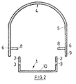
- Each anchor 4 consists of a narrow and flat metal strip 5, which is attached to the attachment before assembly rail 1 is U-shaped as shown in FIG. 2.
- two parallel incisions 7 are made perpendicular to the end face of the metal strip 5, which divide the fastening end 6 into an inner flap 8 and two outer flaps 9, as shown in FIG. 1.
- the anchor 4 bent in a U-shape bears at its fastening end 6 the two outer brackets 9 located parallel in the plane of the bent metal strip 5 and the inner brackets 8 bent inward at right angles therefrom.
- the armature 4 is brought over the fastening rail 1 below it in such a way that the longitudinal slots 3 in the legs 2 of the fastening rail 1 come into a plane with the inner tabs 8 of the armature 4 which protrude at right angles. 3 is deformed by a tool, not shown, the inner tabs 8 penetrate through the longitudinal slots 3 in the legs 2 into the interior of the fastening rail 1, the outer tabs 9 on the outside of the legs 2 for Plant come.
- the inner tabs 8 according to FIG. 4 are then bent inwards, namely parallel to the outer tabs 9 in the direction of the base 10 of the fastening rail 1.
- the anchor 4 is now connected to the fastening rail 1 with very high strength.
- the inner tabs 8 ' are bent outwards at a right angle, as shown in FIG. 5, the fastening ends 6' of the anchor 4 ' engage from the inside in the longitudinal slots 3 'of the leg 2' of the mounting rail 1 ', as shown in Fig.6. Then the inner tabs 8 'parallel to the legs 2 'of the mounting rail 1' bent in the direction of the base 10 'of the mounting rail 1'.
- the fastening rails 1, 1 ' are embedded in a concrete part such that the base 10, 10' lies flush with the surface of the concrete component, so that fastening screws can be screwed through the fastening rail 1, 1 '.
- soft materials such as wood or polystyrene, which prevent concrete from penetrating into the U-shaped interior of the mounting rail 1.1'.
Landscapes
- Engineering & Computer Science (AREA)
- Architecture (AREA)
- Physics & Mathematics (AREA)
- Electromagnetism (AREA)
- Civil Engineering (AREA)
- Structural Engineering (AREA)
- Joining Of Building Structures In Genera (AREA)
- Linear Motors (AREA)
- Railway Tracks (AREA)
Abstract
Die Erfindung bezieht sich auf eine Befestigungsschiene für Trapez bleche in der Bautechnik, mit an den Schenkeln 2 der im Querschnitt U-förmigen Schiene 1 angebrachten Ankern 4.The invention relates to a fastening rail for trapezoidal sheets in construction technology, with anchors 4 attached to the legs 2 of the cross-sectionally U-shaped rail 1.
Zur Erzielung einer herstellungstechnisch einfachen Verbindung zwischen Befestigungsschiene 1 und Anker 4 bei hoher Verbindungsfestigkeit ist erfindungsgemäß vorgesehen, daß die Schenkel 2 der Schiene 1 Längsschlitze 2 aufweisen, daß die aus Metallstreifen 5 gebildeten Anker 4 am Befestigungsende 6 mit zwei sich in Längsrichtung des Metallstreifens 6 erstreckenden, drei Laschen 8,9 bildenden, kurzen Einschnitten 7 versehen sind und daß die innere, mittlere Lasche 8 senkrecht zur Ebene des Metallstreifens 5 abgebogen, durch den zugehörigen Längsschlitz 3 des Schenkels 2 der Schiene 1 gesteckt und auf der anderen Seite des Schenkels 2 umgebogen ist, so daß die beiden äußeren Laschen 9 auf der einen Seite und die inneren, mittlere Lasche 8 auf der anderen Seite des Schenkels 2 anliegen . 
Description
Die Erfindung bezieht sich auf eine Befestigungsschiene für Trapezbleche in der Bautechnik, mit an den Schenkeln der am Querschnitt U-förmigen Schiene angebrachten Ankern.The invention relates to a fastening rail for trapezoidal sheets in construction, with anchors attached to the legs of the cross-sectionally U-shaped rail.
Bei den bekannten Befestigungsschienen für Trapezbleche in der Bautechnik sind die Anker an den Schenkeln der im Querschnitt U-förmigen Schiene angeschweißt. Das Anschweißen ist aufwendig und teuer in der Herstellung.In the known fastening rails for trapezoidal sheets in construction technology, the anchors are welded to the legs of the rail which is U-shaped in cross section. The welding is complex and expensive to manufacture.
Der Erfindung liegt die Aufgabe zugrunde, eine Befestigungs schiene für Trapezbleche in der Bautechnik zu schaffen, deren Anker in herstellungstechnisch einfacher Weise mit den Schenkeln der Befestigungsschiene verbunden sind, wobei insbesondere eine sehr hohe Festigkeit der Verbindung angestrebt wird.The invention has for its object a fastening To create rails for trapezoidal sheets in construction, the anchors are connected in a technically simple manner with the legs of the mounting rail, in particular a very high strength of the connection is sought.
Zur Lösung dieser Aufgabe sieht die Erfindung vor, daß die aus Metallstreifen gebildeten Anker am Befestigungsende mit zwei sich in Längsrichtung des Metallstreifens erstreckenden, drei Laschen bildenden kurzen Einschnitten versehen sind, und daß die mittlere Lasche senkrecht zur Ebene des Metallstreifens abgebogen, durch den zugehörigen Längsschlitz des Schenkels der Schiene gesteckt und auf der anderen Seite des Schenkels umgebogen ist, so daß die beiden äußeren Laschen auf der einen Seite und mittleren Lasche auf der anderen Seite des Schenkels anliegen. Hierdurch wird eine in der Herstellung äußerst einfache Verbindung zwischen Anker und Befestigungsschiene geschaffen, welche eine große Festigkeit aufweist. Die Festigkeit kann insbesondere dadurch erheblich gesteigert werden, daß der mittlere Lappen in Richtung der beiden äußeren Lappen und parallel zu diesen abgebogen ist. Versuche haben gezeigt, daß diese Verbindungstechnik eine sehr hohe Verbindungsfestigkeit hat.To achieve this object, the invention provides that the anchors formed from metal strips at the fastening end are provided with two short incisions extending in the longitudinal direction of the metal strip, forming three tabs, and that the middle tab is bent perpendicular to the plane of the metal strip, through the associated longitudinal slot of the leg of the rail and is bent on the other side of the leg, so that the two outer tabs on one side and middle tab on the other side of the leg. This creates an extremely simple connection between the anchor and the fastening rail, which has a high strength. The strength can in particular be increased considerably in that the middle flap is bent in the direction of the two outer flaps and parallel to them. Tests have shown that this connection technique has a very high connection strength.
Die Erfindung ist nachfolgend anhand eines in den Zeichnungen dargestellten Ausführungsbeispieles einer Befestigungsschiene für Trapezbleche in der Bautechnik näher erläutert. Es zeigen:
- Fig. 1 eine perspektivische Darstellung einer Befestigungsschiene mit einem daran befestigten Anker,
- Fig. 2 einen Querschnitt durch die Befestigungsschiene mit darüber befindlichem Anker vor dessen Verbindung mit der Befestigungsschiene,
- Fig. 3 einen Querschnitt durch die Befestigungsschiene mit daran vorfixiertem Anker,
- Fig. 4 einen Querschnitt durch die Befestigungsschiene mit daran endbefestigtem Anker,
- Fig. 5 einen der Fig. 2 entsprechenden Teilquerschnitt durch die Befestigungsschiene mit einem Teilquerschnitt durch den Anker vor der Verbindung mit der Befestigungsschiene in einer zweiten Ausführungsform,
- Fig. 6 einen der Fig. 3 entsprechenden Teilquerschnitt durch die Befestigungsschiene und den daran vorfixierten Anker in der Ausführungsform gemäß Fig. 5 und
- Fig. 7 einen der Fig. 4 entsprechenden Teilquerschnitt durch die Befestigungsschiene und daran endbefestigtem Anker in der Ausführungsform gemäß den
Figuren 5 und 6.
- 1 is a perspective view of a mounting rail with an anchor attached to it,
- 2 shows a cross section through the fastening rail with the anchor located above it before its connection to the fastening rail,
- 3 shows a cross section through the fastening rail with the anchor pre-fixed thereon,
- 4 shows a cross section through the fastening rail with the armature fixed to it,
- 5 shows a partial cross section corresponding to FIG. 2 through the fastening rail with a partial cross section through the armature before the connection to the fastening rail in a second embodiment,
- FIG. 6 shows a partial cross section corresponding to FIG. 3 through the fastening rail and the anchor pre-fixed thereon in the embodiment according to FIGS. 5 and
- FIG. 7 shows a partial cross section corresponding to FIG. 4 through the fastening rail and an anchor which is end-fastened thereon in the embodiment according to FIGS.
Die in der Fig. 1 in einer Perspektivdarstellung gezeigte Befestigungsschiene 1 ist im Querschnitt U-förmig und umfaßt eine flache Basis 10 sowie zwei rechtwinklig von dieser abstehende Schenkel 2. In die Randbereiche der Schenkel 2 sind an diametral gegenüberliegenden Stellen Längsschlitze 3 zur Befestigung von Ankern 4 eingebracht. Jeder Anker 4 besteht aus einem schmalen und flachen Metallstreifen 5, der vor der Montage mit der Befestigungs schiene 1 gemäß Fig. 2 U-förmig ausgeformt ist. Am Befestigungsende 6 sind senkrecht zur Stirnfläche des Metallstreifens 5 zwei parallele Einschnitte 7 eingebracht, welche das Befestigungsende 6 in eine innere Lasche 8 und zwei äußere Laschen 9 unterteilen, wie es in Fig. 1 dargestellt ist.The fastening rail 1 shown in a perspective view in FIG. 1 is U-shaped in cross-section and comprises a
Der vor der Montage gemäß Fig. 2 U-förmig gebogene Anker 4 trägt vor der Montage an seinem Befestigungsende 6 die parallel in der Ebene des gebogenen Metallstreifens 5 befindlichen beiden äußeren Laschen 9 und die hiervon rechtwinklig nach innen abgebogenen inneren Laschen 8. In diesem Zustand wird der Anker 4 über die darunter befindliche Befestigungsschiene 1 derart gebracht, daß die Längsschlitze 3 in den Schenkeln 2 der Befestigungsschiene 1 in eine Ebene mit den rechtwinklig abstehenden inneren Laschen 8 des Ankers 4 gelangen. Nun wird der Anker 4 gemäß Fig. 3 durch ein nicht näher dargestelltes Werkzeug verformt, wobei die inneren Laschen 8 durch die Längsschlitze 3 in den Schenkeln 2 in das Innere der Befestigungsschiene 1 eindringen, wobei die äußeren Laschen 9 auf der Außenseite der Schenkel 2 zur Anlage kommen. Anschließend werden die inneren Laschen 8 gemäß Fig. 4 nach innen abgebogen und zwar parallel zu den äußeren Laschen 9 in Richtung auf die Basis 10 der Befestigungsschiene 1. Der Anker 4 ist nunmehr mit sehr hoher Festigkeit mit der Befestigungsschiene 1 verbunden.Before assembly, the
In der in den Figuren 5 bis 7 dargestellten zweiten Ausfflhrungsform der Verbindung zwischen Anker 4′ und Befestigungsschiene 1′ sind die inneren Laschen 8′ rechtwinklig nach außen abgebogen, wie es in Fig. 5 dargestellt ist, wobei die Befestigungsenden 6′ des Ankers 4′ von innen in die Längsschlitze 3′ der Schenkel 2′ der Befestigungsschiene 1′ eingreifen, wie es in Fig.6 dargestellt ist. Anschließend werden die inneren Laschen 8′ parallel zu den Schenkeln 2′ der Befestigungsschiene 1′ abgebogen und zwar in Richtung auf die Basis 10′ der Befestigungsschiene 1′. Auch hierdurch wird eine Verbindung zwischen Befestigungsschiene 1′ und Anker 4′ mit sehr hoher Festigkeit geschaffen, wobei die Form des von der Befestigungsschiene 1′ hervorstehenden Ankers 4 sich von der Form des Ankers 4 gemäß den Figuren 1 und 3,4 dadurch unterscheidet, daß der Anker 4′ als gerader Metallstreifen 5′ ausgebildet ist, der gegebenenfalls mit Durchbrüchen zur besseren Verbindung mit dem Betonbauteil versehen sein kann.In the second embodiment of the connection between anchor 4 'and fastening rail 1' shown in FIGS. 5 to 7, the inner tabs 8 'are bent outwards at a right angle, as shown in FIG. 5, the fastening ends 6' of the anchor 4 ' engage from the inside in the longitudinal slots 3 'of the leg 2' of the mounting rail 1 ', as shown in Fig.6. Then the inner tabs 8 'parallel to the legs 2 'of the mounting rail 1' bent in the direction of the base 10 'of the mounting rail 1'. This also creates a connection between the fastening rail 1 'and anchor 4' with very high strength, the shape of the
In bekannter Weise werden die Befestigungsschienen 1, 1′ in ein Betonteil derart eingebettet, daß die Basis 10, 10′ bündig mit der Oberfläche des Betonbauteiles liegt, so daß durch die Befestigungsschiene 1,1′ hindurch Befestigungsschrauben geschraubt werden können. Im Innenraum der Befestigungsschiene 1,1′ befinden sich dann weiche Materialien, wie Holz oder Polystyrol, die ein Eindringen von Beton in den U-förmigen Innenraum der Befestigungsschiene 1,1′ verhindern.In a known manner, the fastening rails 1, 1 'are embedded in a concrete part such that the
Claims (2)
Applications Claiming Priority (2)
| Application Number | Priority Date | Filing Date | Title |
|---|---|---|---|
| DE19893912169 DE3912169C1 (en) | 1989-04-13 | 1989-04-13 | |
| DE3912169 | 1989-04-13 |
Publications (3)
| Publication Number | Publication Date |
|---|---|
| EP0397293A2 true EP0397293A2 (en) | 1990-11-14 |
| EP0397293A3 EP0397293A3 (en) | 1992-12-16 |
| EP0397293B1 EP0397293B1 (en) | 1994-10-19 |
Family
ID=6378623
Family Applications (1)
| Application Number | Title | Priority Date | Filing Date |
|---|---|---|---|
| EP19900250088 Expired - Lifetime EP0397293B1 (en) | 1989-04-13 | 1990-04-03 | Fixing rail for sheets with trapezoidal corrugations for structural engineering |
Country Status (2)
| Country | Link |
|---|---|
| EP (1) | EP0397293B1 (en) |
| DE (1) | DE3912169C1 (en) |
Cited By (1)
| Publication number | Priority date | Publication date | Assignee | Title |
|---|---|---|---|---|
| FR2807773A1 (en) * | 2000-04-14 | 2001-10-19 | Owens Corning Internat Buildin | Supporting wall construction procedure incorporating built-in fixings for facing panels has metal clamp strips inserted between courses of blocks |
Families Citing this family (1)
| Publication number | Priority date | Publication date | Assignee | Title |
|---|---|---|---|---|
| DE202009015920U1 (en) | 2009-11-23 | 2010-03-11 | Profilanker Gmbh | mounting rail |
Family Cites Families (3)
| Publication number | Priority date | Publication date | Assignee | Title |
|---|---|---|---|---|
| DE7520911U (en) * | 1975-07-02 | 1976-01-29 | Halfeneisen Gmbh & Co Kg, 4000 Duesseldorf | ANCHOR RAIL |
| US4596102A (en) * | 1984-01-12 | 1986-06-24 | Dur-O-Wal, Inc. | Anchor for masonry veneer |
| GB2193513A (en) * | 1986-08-05 | 1988-02-10 | Harris & Edgar Limited | A channel and wall tie |
-
1989
- 1989-04-13 DE DE19893912169 patent/DE3912169C1/de not_active Expired - Fee Related
-
1990
- 1990-04-03 EP EP19900250088 patent/EP0397293B1/en not_active Expired - Lifetime
Cited By (1)
| Publication number | Priority date | Publication date | Assignee | Title |
|---|---|---|---|---|
| FR2807773A1 (en) * | 2000-04-14 | 2001-10-19 | Owens Corning Internat Buildin | Supporting wall construction procedure incorporating built-in fixings for facing panels has metal clamp strips inserted between courses of blocks |
Also Published As
| Publication number | Publication date |
|---|---|
| EP0397293A3 (en) | 1992-12-16 |
| DE3912169C1 (en) | 1990-12-13 |
| EP0397293B1 (en) | 1994-10-19 |
Similar Documents
| Publication | Publication Date | Title |
|---|---|---|
| WO2001025664A2 (en) | Assembly rail formed out of at least one profile element | |
| DE3435776A1 (en) | BUILDING ELEMENT AND ROOF CONSTRUCTION CONSTRUCTED FROM A VARIETY OF SUCH ELEMENTS | |
| DE2754087A1 (en) | DEVICE FOR FASTENING CEILING PANELS | |
| EP0143299A2 (en) | Corner or edge protector | |
| CH666931A5 (en) | Lost shuttering securement for concrete reinforcement - has U=shaped member, whose web has elongated holes, transverse to shuttering longitudinal axis | |
| EP1508654B1 (en) | Hollow profile to attach objects | |
| DE2613522C3 (en) | Claw plate intended for wood connections | |
| EP0397293B1 (en) | Fixing rail for sheets with trapezoidal corrugations for structural engineering | |
| DE2648467A1 (en) | Bolt fixture for motor vehicle bumper - has U-form clamp strip retained in bumper plate aperture by sprung integral arms | |
| DE4022444A1 (en) | METHOD FOR FIXING CONNECTING METALLIC COMPONENTS TO A METALLIC CARRIER | |
| DE2626443A1 (en) | PANEL CONNECTOR AND METHOD FOR FASTENING IT TO THE TAPE ENDS OF CONVEYOR BELTS | |
| EP0152015B1 (en) | Apparatus for flashing reinforcement steel | |
| DE4327411C2 (en) | Profile part with a claw slidably arranged in sliding grooves | |
| DE3231173C2 (en) | Composite element made of rigid foam core and cover layers | |
| DE909036C (en) | Device for connecting building panels or the like. | |
| EP0525661A1 (en) | Shuttering for concrete construction and method for the manufacturing of the shuttering | |
| DE2233200C3 (en) | ||
| EP0165367A1 (en) | Reinforcement-iron holder for use in joining cast concrete work | |
| DE2543950C2 (en) | U-shaped component | |
| DE2128553A1 (en) | WEDGE FLASH | |
| DE1609393A1 (en) | Connecting element for connecting two crossed profile supports | |
| DE1609973C (en) | Made of sheet metal and designed as a hollow profile rung for glass roofs or the like | |
| DE3531254C2 (en) | ||
| DE202019005047U1 (en) | Concrete construction element and reinforcement arrangement, in particular for a concrete construction element | |
| DE20311075U1 (en) | Fastening for connecting of especially fences and/or clamping elements of fence to post has interfitting connecting components provided on clamp and connecting element to fix connecting element to clamp |
Legal Events
| Date | Code | Title | Description |
|---|---|---|---|
| PUAI | Public reference made under article 153(3) epc to a published international application that has entered the european phase |
Free format text: ORIGINAL CODE: 0009012 |
|
| AK | Designated contracting states |
Kind code of ref document: A2 Designated state(s): CH FR GB IT LI |
|
| 17P | Request for examination filed |
Effective date: 19901207 |
|
| PUAL | Search report despatched |
Free format text: ORIGINAL CODE: 0009013 |
|
| AK | Designated contracting states |
Kind code of ref document: A3 Designated state(s): CH FR GB IT LI |
|
| 17Q | First examination report despatched |
Effective date: 19931222 |
|
| GRAA | (expected) grant |
Free format text: ORIGINAL CODE: 0009210 |
|
| ITF | It: translation for a ep patent filed | ||
| AK | Designated contracting states |
Kind code of ref document: B1 Designated state(s): CH FR GB IT LI |
|
| GBT | Gb: translation of ep patent filed (gb section 77(6)(a)/1977) |
Effective date: 19941110 |
|
| REG | Reference to a national code |
Ref country code: CH Ref legal event code: PFA Free format text: DEUTSCHE KAHNEISEN GESELLSCHAFT MBH |
|
| ET | Fr: translation filed | ||
| REG | Reference to a national code |
Ref country code: FR Ref legal event code: CD |
|
| PLBE | No opposition filed within time limit |
Free format text: ORIGINAL CODE: 0009261 |
|
| STAA | Information on the status of an ep patent application or granted ep patent |
Free format text: STATUS: NO OPPOSITION FILED WITHIN TIME LIMIT |
|
| 26N | No opposition filed | ||
| ITPR | It: changes in ownership of a european patent |
Owner name: CAMBIO DI NOME;DEUTSCHE KAHNEEISEN GMBH |
|
| PGFP | Annual fee paid to national office [announced via postgrant information from national office to epo] |
Ref country code: GB Payment date: 19980406 Year of fee payment: 9 |
|
| PGFP | Annual fee paid to national office [announced via postgrant information from national office to epo] |
Ref country code: FR Payment date: 19980417 Year of fee payment: 9 |
|
| PGFP | Annual fee paid to national office [announced via postgrant information from national office to epo] |
Ref country code: CH Payment date: 19980424 Year of fee payment: 9 |
|
| PG25 | Lapsed in a contracting state [announced via postgrant information from national office to epo] |
Ref country code: GB Free format text: LAPSE BECAUSE OF NON-PAYMENT OF DUE FEES Effective date: 19990403 |
|
| PG25 | Lapsed in a contracting state [announced via postgrant information from national office to epo] |
Ref country code: LI Free format text: LAPSE BECAUSE OF NON-PAYMENT OF DUE FEES Effective date: 19990430 Ref country code: CH Free format text: LAPSE BECAUSE OF NON-PAYMENT OF DUE FEES Effective date: 19990430 |
|
| GBPC | Gb: european patent ceased through non-payment of renewal fee |
Effective date: 19990403 |
|
| REG | Reference to a national code |
Ref country code: CH Ref legal event code: PL |
|
| PG25 | Lapsed in a contracting state [announced via postgrant information from national office to epo] |
Ref country code: FR Free format text: LAPSE BECAUSE OF NON-PAYMENT OF DUE FEES Effective date: 19991231 |
|
| REG | Reference to a national code |
Ref country code: FR Ref legal event code: ST |
|
| PG25 | Lapsed in a contracting state [announced via postgrant information from national office to epo] |
Ref country code: IT Free format text: LAPSE BECAUSE OF NON-PAYMENT OF DUE FEES;WARNING: LAPSES OF ITALIAN PATENTS WITH EFFECTIVE DATE BEFORE 2007 MAY HAVE OCCURRED AT ANY TIME BEFORE 2007. THE CORRECT EFFECTIVE DATE MAY BE DIFFERENT FROM THE ONE RECORDED. Effective date: 20050403 |