EP0393729A2 - Regenerable filter in exhaust gases of an internal-combustion engine - Google Patents
Regenerable filter in exhaust gases of an internal-combustion engine Download PDFInfo
- Publication number
- EP0393729A2 EP0393729A2 EP90110810A EP90110810A EP0393729A2 EP 0393729 A2 EP0393729 A2 EP 0393729A2 EP 90110810 A EP90110810 A EP 90110810A EP 90110810 A EP90110810 A EP 90110810A EP 0393729 A2 EP0393729 A2 EP 0393729A2
- Authority
- EP
- European Patent Office
- Prior art keywords
- cavities
- filter
- cells
- walls
- electrically
- Prior art date
- Legal status (The legal status is an assumption and is not a legal conclusion. Google has not performed a legal analysis and makes no representation as to the accuracy of the status listed.)
- Granted
Links
Images

Classifications
-
- F—MECHANICAL ENGINEERING; LIGHTING; HEATING; WEAPONS; BLASTING
- F01—MACHINES OR ENGINES IN GENERAL; ENGINE PLANTS IN GENERAL; STEAM ENGINES
- F01N—GAS-FLOW SILENCERS OR EXHAUST APPARATUS FOR MACHINES OR ENGINES IN GENERAL; GAS-FLOW SILENCERS OR EXHAUST APPARATUS FOR INTERNAL-COMBUSTION ENGINES
- F01N3/00—Exhaust or silencing apparatus having means for purifying, rendering innocuous, or otherwise treating exhaust
- F01N3/02—Exhaust or silencing apparatus having means for purifying, rendering innocuous, or otherwise treating exhaust for cooling, or for removing solid constituents of, exhaust
- F01N3/021—Exhaust or silencing apparatus having means for purifying, rendering innocuous, or otherwise treating exhaust for cooling, or for removing solid constituents of, exhaust by means of filters
- F01N3/0217—Exhaust or silencing apparatus having means for purifying, rendering innocuous, or otherwise treating exhaust for cooling, or for removing solid constituents of, exhaust by means of filters the filtering elements having the form of hollow cylindrical bodies
-
- F—MECHANICAL ENGINEERING; LIGHTING; HEATING; WEAPONS; BLASTING
- F01—MACHINES OR ENGINES IN GENERAL; ENGINE PLANTS IN GENERAL; STEAM ENGINES
- F01N—GAS-FLOW SILENCERS OR EXHAUST APPARATUS FOR MACHINES OR ENGINES IN GENERAL; GAS-FLOW SILENCERS OR EXHAUST APPARATUS FOR INTERNAL-COMBUSTION ENGINES
- F01N3/00—Exhaust or silencing apparatus having means for purifying, rendering innocuous, or otherwise treating exhaust
- F01N3/02—Exhaust or silencing apparatus having means for purifying, rendering innocuous, or otherwise treating exhaust for cooling, or for removing solid constituents of, exhaust
- F01N3/021—Exhaust or silencing apparatus having means for purifying, rendering innocuous, or otherwise treating exhaust for cooling, or for removing solid constituents of, exhaust by means of filters
- F01N3/0218—Exhaust or silencing apparatus having means for purifying, rendering innocuous, or otherwise treating exhaust for cooling, or for removing solid constituents of, exhaust by means of filters the filtering elements being made from spirally-wound filtering material
-
- F—MECHANICAL ENGINEERING; LIGHTING; HEATING; WEAPONS; BLASTING
- F01—MACHINES OR ENGINES IN GENERAL; ENGINE PLANTS IN GENERAL; STEAM ENGINES
- F01N—GAS-FLOW SILENCERS OR EXHAUST APPARATUS FOR MACHINES OR ENGINES IN GENERAL; GAS-FLOW SILENCERS OR EXHAUST APPARATUS FOR INTERNAL-COMBUSTION ENGINES
- F01N3/00—Exhaust or silencing apparatus having means for purifying, rendering innocuous, or otherwise treating exhaust
- F01N3/02—Exhaust or silencing apparatus having means for purifying, rendering innocuous, or otherwise treating exhaust for cooling, or for removing solid constituents of, exhaust
- F01N3/021—Exhaust or silencing apparatus having means for purifying, rendering innocuous, or otherwise treating exhaust for cooling, or for removing solid constituents of, exhaust by means of filters
- F01N3/022—Exhaust or silencing apparatus having means for purifying, rendering innocuous, or otherwise treating exhaust for cooling, or for removing solid constituents of, exhaust by means of filters characterised by specially adapted filtering structure, e.g. honeycomb, mesh or fibrous
-
- F—MECHANICAL ENGINEERING; LIGHTING; HEATING; WEAPONS; BLASTING
- F01—MACHINES OR ENGINES IN GENERAL; ENGINE PLANTS IN GENERAL; STEAM ENGINES
- F01N—GAS-FLOW SILENCERS OR EXHAUST APPARATUS FOR MACHINES OR ENGINES IN GENERAL; GAS-FLOW SILENCERS OR EXHAUST APPARATUS FOR INTERNAL-COMBUSTION ENGINES
- F01N3/00—Exhaust or silencing apparatus having means for purifying, rendering innocuous, or otherwise treating exhaust
- F01N3/02—Exhaust or silencing apparatus having means for purifying, rendering innocuous, or otherwise treating exhaust for cooling, or for removing solid constituents of, exhaust
- F01N3/021—Exhaust or silencing apparatus having means for purifying, rendering innocuous, or otherwise treating exhaust for cooling, or for removing solid constituents of, exhaust by means of filters
- F01N3/022—Exhaust or silencing apparatus having means for purifying, rendering innocuous, or otherwise treating exhaust for cooling, or for removing solid constituents of, exhaust by means of filters characterised by specially adapted filtering structure, e.g. honeycomb, mesh or fibrous
- F01N3/0222—Exhaust or silencing apparatus having means for purifying, rendering innocuous, or otherwise treating exhaust for cooling, or for removing solid constituents of, exhaust by means of filters characterised by specially adapted filtering structure, e.g. honeycomb, mesh or fibrous the structure being monolithic, e.g. honeycombs
-
- F—MECHANICAL ENGINEERING; LIGHTING; HEATING; WEAPONS; BLASTING
- F01—MACHINES OR ENGINES IN GENERAL; ENGINE PLANTS IN GENERAL; STEAM ENGINES
- F01N—GAS-FLOW SILENCERS OR EXHAUST APPARATUS FOR MACHINES OR ENGINES IN GENERAL; GAS-FLOW SILENCERS OR EXHAUST APPARATUS FOR INTERNAL-COMBUSTION ENGINES
- F01N3/00—Exhaust or silencing apparatus having means for purifying, rendering innocuous, or otherwise treating exhaust
- F01N3/02—Exhaust or silencing apparatus having means for purifying, rendering innocuous, or otherwise treating exhaust for cooling, or for removing solid constituents of, exhaust
- F01N3/021—Exhaust or silencing apparatus having means for purifying, rendering innocuous, or otherwise treating exhaust for cooling, or for removing solid constituents of, exhaust by means of filters
- F01N3/023—Exhaust or silencing apparatus having means for purifying, rendering innocuous, or otherwise treating exhaust for cooling, or for removing solid constituents of, exhaust by means of filters using means for regenerating the filters, e.g. by burning trapped particles
- F01N3/027—Exhaust or silencing apparatus having means for purifying, rendering innocuous, or otherwise treating exhaust for cooling, or for removing solid constituents of, exhaust by means of filters using means for regenerating the filters, e.g. by burning trapped particles using electric or magnetic heating means
-
- F—MECHANICAL ENGINEERING; LIGHTING; HEATING; WEAPONS; BLASTING
- F01—MACHINES OR ENGINES IN GENERAL; ENGINE PLANTS IN GENERAL; STEAM ENGINES
- F01N—GAS-FLOW SILENCERS OR EXHAUST APPARATUS FOR MACHINES OR ENGINES IN GENERAL; GAS-FLOW SILENCERS OR EXHAUST APPARATUS FOR INTERNAL-COMBUSTION ENGINES
- F01N2330/00—Structure of catalyst support or particle filter
- F01N2330/10—Fibrous material, e.g. mineral or metallic wool
-
- F—MECHANICAL ENGINEERING; LIGHTING; HEATING; WEAPONS; BLASTING
- F01—MACHINES OR ENGINES IN GENERAL; ENGINE PLANTS IN GENERAL; STEAM ENGINES
- F01N—GAS-FLOW SILENCERS OR EXHAUST APPARATUS FOR MACHINES OR ENGINES IN GENERAL; GAS-FLOW SILENCERS OR EXHAUST APPARATUS FOR INTERNAL-COMBUSTION ENGINES
- F01N2370/00—Selection of materials for exhaust purification
- F01N2370/22—Selection of materials for exhaust purification used in non-catalytic purification apparatus
Definitions
- This invention relates to a regenerable filter in the exhaust gases of an internal-combustion engine.
- this invention relates to a filter suited to be placed into an exhaust pipe of an internal-combustion engine, comprising a filtering member suited to intercept the residual combustion products contained in the exhaust gases and further comprising means suited to produce the combustion of said residues.
- Filters are known in which said means suited to produce the combustion of the residues are of the kind that uses a catalyst for the starting of the combustion at low temperatures, or of the kind that heats the exhaust gases, upstream of the filtering member, to the combustion temperature of said residues.
- a further drawback of the known heating filters is the fact that the filter temperature can increase exceedingly, since the regeneration usually takes place upon rather wide surfaces and so in a scarcely controlled manner; as a result there is the possibility of serious damages or destruction due to exaggerated heatings.
- filters For the double object of limiting the average temperature of the filter and reducing the electric power used, filters have been realized in which the filtering member is cyclically heated in relation with consecutive portions; the continuity of the filtering member nevertheless can allow the starting of wide and intense combustions. Furthermore, since the known filters of this kind the heating of the consecutive portions of the filtering member is obtained through convection and radiation, the electric power overall supplied, is always substantially higher than the equivalent of the thermal power actually needed to locally start the combustion of the residues.
- An object of the present invention is to realize a regenerable filter for the exhaust gases of an internal-combustion engine, that lacks in the drawbacks connected with the above mentioned and known filters, and is particularly simple, practical, and removes the risks of clogging or self-destruction due to exaggerated heating.
- a regenerable filter in the exhaust gases of an internal-combustion engine comprising an outer casing provided with at least an inlet duct and at least an outlet duct, filtering means housed into said outer casing and including a set of pairs of cavities having walls made of porous material, each one of said cavities being provided with an open end and a closed end, one cavity of each pair being provided with its open end communicating with said inlet duct, the other cavity of each pair being provided with its open end communicating with said outlet duct, whereby said porous material is apt to intercept the residual combustion products of said gases, electric heating means associated with said pairs of cavities for raising the temperature of said products, and selectively and/or cyclically operable control means for electrically supplying said heating means, characterized by a plurality of elongated honey-comb cells of a prismatic shape, each one including at least one pair of said cavities, said porous material being electrically conductive, said plurality of cells being arranged in a retic
- regenerable filter for an internal-combustion engine, in particular of the compression-ignition type.
- the filter 1 comprises a cylindric outer casing 2, schematically shown in dotted line in figure 1, and a filtering member 3 housed into said casing 2.
- the filtering member 3 comprises a plurality of honey-comb cells 4, suitably obtained from a porous and electrically conductive meal, for instance of the ceramic type.
- Each cell 4 having an elongated prismatic shape with square section, comprises four side walls 5 and two inner division walls 6, mutually orthogonal and located along the middle planes of the cell 4, so as to define four square section cavities 7.
- Cavities 7 are closed at one end by a front wall 8, and open at the opposite end; in particular, two diagonally opposed cavities 7 of each cell are open at one end 9, the other two cavities of the same cell 4 being open at an opposite end 10.
- each cell 4 is arranged into a corresponding seat 11 of a reticulated structure 12, realized in an electrically and thermally insulating material, defined by two orders of flat, parallel and equidistant walls 13, perpendicularly intersecting one another.
- Cells 4 are connected at one end 9 by means of respective electric cables 14, to the positive pole of the vehicle battery; said connection is subject to the action of interruption means 15, for instance controlled diodes, controlled by a conventional control exchange 16.
- the opposite ends 10 of cells 4 are connected to a metal plate 17 of the casing 2, which is provided with apertures 18 facing corresponding apertures of the cells 4 themselves, and is in electric connection with a negative pole of the vehicle battery.
- the operation of the filter is as follows.
- the exhaust gases emitted by the engine are conveyed in a known manner into the casing 2 of the filter 1 and enter in the cavities 7 open on the side of the end 9. Since these cavities are closed at the opposite end by the front walls 8, gases are constrained to pass through the walls 6, which intercept the residual combustion products, in order to go in the adjacent cavities 7 which are open on the side of the end 10 and allow the discharge of gases from filter 1 through the apertures 18 of the plate 17.
- the build-up of residues in the walls 6 originates a gradual clogging of the filter, creating a back-pressure in the engine exhaust.
- the control exchange 16 as a result of a signal received, for instance, from a pressure sensor detecting the pressure difference of the exhaust gas between inlet and outlet from the filter 1, causes the closing of one of the switches 15.
- one of the cells 4 is electrically supplied through the circuit formed by the respective cable 14, the cell 4 and the plate 17.
- the flow of electric current through the walls 5 and 6 of the cell 4 gives rise to a heating by Joule effect of the walls till the combustion temperature of the residues is attained, which are oxidized and gassified freeing the porosity of the cell.
- control exchange 16 disconnects the supply to the cell 4 and supplies the subsequent cell 4. All the cells are supplied in sequence, according to an order and for a time predetermined or governed from time to time by the control exchange 16.
- the exchange 16 can control the intensity of current and the heating time of each cell 4 as a function of the revolutions of the engine and of the rate of flow of the air passing through the filter 1 by the action of an appropriate device, for instance a fan or a positive-displacement pump.
- the conductive portions 4 of the filtering members 3 are mutually insulated. This enables to obtain a selective and cyclic heating of the portions, with the advantage of reducing the electric power used and keeping under control the temperature of the filtering elements 3, without any risk of clogging or of destruction due to over-heating. Further, the heating of the residues takes place through conduction, that is through direct contact between the residues themselves and the conductive portions 4, which enables to exploit the most of the power supplied for the starting of the combustion, without great losses due to convection.
- the ceramic filtering members 3 can have a good resistance to thermal shocks, since they are subdivided in a plurality of cells 4 having reduced dimensions and being mutually thermally insulated.
- the fibers used are suitably subjected to pre-treatments apt to avoid the embrittlement and/or the possible breakage due to phase transformation or anyway to other phenomena produced by thermal shocks.
- the pre-treatments can be of chemical and/or physical nature, and depending on the type of fiber used said treatments consist in the introduction or extraction of ions through diffusion in the material of the fiber.
- the filtering member can be produced with a combination of ceramic fabrics, felts or boards.
- the filtering member can comprise a series of stratified felt members; in particular, the single layers of the filtering member can be provided with pores having a geometric distribution, different dimensions and shapes, and arranged according to a porosity gradient.
- the electrification of the various elements can be carried out introducing in such elements electrically conductive fibers or threads. This solution enables to reduce the effect of the thermal shocks, in that the thermal conductivity is increased.
- a sliding element substantially arranged on a central plane of an inner chamber of the filter, in this case suitably formed with a quadrangular cross-section, and which can readily be introduced and extracted from the outer casing of the filter.
- control switches 15 in response to signals received from the user and/or from process sensors (for instance temperature or pressure sensors) arranged inside or outside the filter; the electric current supplying the conductive portions 4 can be modulated according to the temperature levels established in the filter.
- process sensors for instance temperature or pressure sensors
- Means for the introduction of air into the filter can be provided, in order to assure a sufficient partial pressure of oxygen in the exhaust gases and so a complete combustion of the residues.
- At last catalysing additives can be provided suited to aid and optimize the combustion of the solid unburned particles.
- said additives can suitably comprise a mixture of one or more metal-oxides, for instance CuO, Cu2O, MnO2, Mn3O4, PbO, CeO2 or the respective oxygenated salts, for instance Cu(NO3)2, CuSO4, and of one or more chlorides of an alkaline or alkaline-earth metal for instance NaCl, KCl, LiCl, CuCl, CuCl2, MgCl2, BaCl2, possibly also in the hydrated form; preferably said mixture comprises CuO and NaCl.
- Said mixture can be in a solid form (powder) or in the form of a solution in water or other solvent, and is deposited on the filtering member in the more convenient manner, such as insufflation, spraying or immersion.
Landscapes
- Engineering & Computer Science (AREA)
- Chemical & Material Sciences (AREA)
- Combustion & Propulsion (AREA)
- Mechanical Engineering (AREA)
- General Engineering & Computer Science (AREA)
- Processes For Solid Components From Exhaust (AREA)
- Filtering Materials (AREA)
- Filtering Of Dispersed Particles In Gases (AREA)
Abstract
Description
- This invention relates to a regenerable filter in the exhaust gases of an internal-combustion engine. In particular, this invention relates to a filter suited to be placed into an exhaust pipe of an internal-combustion engine, comprising a filtering member suited to intercept the residual combustion products contained in the exhaust gases and further comprising means suited to produce the combustion of said residues.
- Filters are known in which said means suited to produce the combustion of the residues are of the kind that uses a catalyst for the starting of the combustion at low temperatures, or of the kind that heats the exhaust gases, upstream of the filtering member, to the combustion temperature of said residues.
- Said filters suffer from certain drawbacks.
- In the case of the entirely catalytic filters, it is not uncommon the so-called "poisoning" of the catalyst, due to the presence in the exhaust gases of chemicals that impair their catalytic activity to the point of completely discontinue the combustion of the residues; this originates a gradual clogging of the filter, with the resulting attainment of an unacceptable back-pressure on the engine exhaust.
- In the case of heating filters, one of which is disclosed in the US-A- 4 276 066, the heating of the exhaust gases usually takes place by means of resistive elements positioned upstream of the filtering member, which, supplied with an electric current, generate thermal power through Joule effect and rise the temperature of the gases that affect then the filtering surface. This solution entails a high consumption of electric power, with the risk of extreme charge losses of the vehicle battery.
- A further drawback of the known heating filters is the fact that the filter temperature can increase exceedingly, since the regeneration usually takes place upon rather wide surfaces and so in a scarcely controlled manner; as a result there is the possibility of serious damages or destruction due to exaggerated heatings.
- For the double object of limiting the average temperature of the filter and reducing the electric power used, filters have been realized in which the filtering member is cyclically heated in relation with consecutive portions; the continuity of the filtering member nevertheless can allow the starting of wide and intense combustions. Furthermore, since the known filters of this kind the heating of the consecutive portions of the filtering member is obtained through convection and radiation, the electric power overall supplied, is always substantially higher than the equivalent of the thermal power actually needed to locally start the combustion of the residues.
- Solutions in which diesel oil or other fuel burners in substitution for said resistive elements are used, are also known; said solutions have however high costs and dimensions together with said problems connected with the regeneration.
- An object of the present invention is to realize a regenerable filter for the exhaust gases of an internal-combustion engine, that lacks in the drawbacks connected with the above mentioned and known filters, and is particularly simple, practical, and removes the risks of clogging or self-destruction due to exaggerated heating.
- Said object is attained by the present invention in that it relates to a regenerable filter in the exhaust gases of an internal-combustion engine, comprising an outer casing provided with at least an inlet duct and at least an outlet duct, filtering means housed into said outer casing and including a set of pairs of cavities having walls made of porous material, each one of said cavities being provided with an open end and a closed end, one cavity of each pair being provided with its open end communicating with said inlet duct, the other cavity of each pair being provided with its open end communicating with said outlet duct, whereby said porous material is apt to intercept the residual combustion products of said gases, electric heating means associated with said pairs of cavities for raising the temperature of said products, and selectively and/or cyclically operable control means for electrically supplying said heating means, characterized by a plurality of elongated honey-comb cells of a prismatic shape, each one including at least one pair of said cavities, said porous material being electrically conductive, said plurality of cells being arranged in a reticulate structure defined by two orders of intersecting flat walls made of an electrically and thermally insulating material to insulate said cells from each other, the two ends of the cavities of each cell being electrically connected to said control means to be selectively and/or cyclically electrically supplied by the intermediary of said control means.
- For a better understanding of the present invention, a preferred embodiment is described below, as a non limiting example and referring to the accompanying drawings, in which:
- - figure 1 is a perspective view of a regenerable filter according to the present invention;
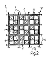
- - figure 2 is a front view, partial and in enlarged scale of a detail of figure 1.
- Referring in particular to figures 1 and 2, it is designated generally by 1 a regenerable filter for an internal-combustion engine, in particular of the compression-ignition type.
- The filter 1 comprises a cylindric
outer casing 2, schematically shown in dotted line in figure 1, and afiltering member 3 housed into saidcasing 2. - The filtering
member 3 comprises a plurality of honey-comb cells 4, suitably obtained from a porous and electrically conductive meal, for instance of the ceramic type. Each cell 4, having an elongated prismatic shape with square section, comprises fourside walls 5 and twoinner division walls 6, mutually orthogonal and located along the middle planes of the cell 4, so as to define foursquare section cavities 7.Cavities 7 are closed at one end by a front wall 8, and open at the opposite end; in particular, two diagonally opposedcavities 7 of each cell are open at one end 9, the other two cavities of the same cell 4 being open at anopposite end 10. - According to the present invention, each cell 4 is arranged into a
corresponding seat 11 of a reticulatedstructure 12, realized in an electrically and thermally insulating material, defined by two orders of flat, parallel andequidistant walls 13, perpendicularly intersecting one another. - Cells 4 are connected at one end 9 by means of respective
electric cables 14, to the positive pole of the vehicle battery; said connection is subject to the action of interruption means 15, for instance controlled diodes, controlled by aconventional control exchange 16. Theopposite ends 10 of cells 4 are connected to ametal plate 17 of thecasing 2, which is provided with apertures 18 facing corresponding apertures of the cells 4 themselves, and is in electric connection with a negative pole of the vehicle battery. - The operation of the filter is as follows.
- The exhaust gases emitted by the engine are conveyed in a known manner into the
casing 2 of the filter 1 and enter in thecavities 7 open on the side of the end 9. Since these cavities are closed at the opposite end by the front walls 8, gases are constrained to pass through thewalls 6, which intercept the residual combustion products, in order to go in theadjacent cavities 7 which are open on the side of theend 10 and allow the discharge of gases from filter 1 through the apertures 18 of theplate 17. The build-up of residues in thewalls 6 originates a gradual clogging of the filter, creating a back-pressure in the engine exhaust. Thecontrol exchange 16, as a result of a signal received, for instance, from a pressure sensor detecting the pressure difference of the exhaust gas between inlet and outlet from the filter 1, causes the closing of one of theswitches 15. Consequently one of the cells 4 is electrically supplied through the circuit formed by therespective cable 14, the cell 4 and theplate 17. The flow of electric current through thewalls - Subsequently, the
control exchange 16 disconnects the supply to the cell 4 and supplies the subsequent cell 4. All the cells are supplied in sequence, according to an order and for a time predetermined or governed from time to time by thecontrol exchange 16. For instance, theexchange 16 can control the intensity of current and the heating time of each cell 4 as a function of the revolutions of the engine and of the rate of flow of the air passing through the filter 1 by the action of an appropriate device, for instance a fan or a positive-displacement pump. - From an examination of the features of the filters realized according to the present invention, the advantages they allow to attain are obvious.
- First of all, the conductive portions 4 of the filtering
members 3 are mutually insulated. This enables to obtain a selective and cyclic heating of the portions, with the advantage of reducing the electric power used and keeping under control the temperature of thefiltering elements 3, without any risk of clogging or of destruction due to over-heating. Further, the heating of the residues takes place through conduction, that is through direct contact between the residues themselves and the conductive portions 4, which enables to exploit the most of the power supplied for the starting of the combustion, without great losses due to convection. - The
ceramic filtering members 3 can have a good resistance to thermal shocks, since they are subdivided in a plurality of cells 4 having reduced dimensions and being mutually thermally insulated. - In this connection, the fibers used are suitably subjected to pre-treatments apt to avoid the embrittlement and/or the possible breakage due to phase transformation or anyway to other phenomena produced by thermal shocks. The pre-treatments can be of chemical and/or physical nature, and depending on the type of fiber used said treatments consist in the introduction or extraction of ions through diffusion in the material of the fiber.
- It is then obvious that to the filter 1, described can be introduced changes or variations, without departing from the scope of the present invention. In particular, the shape, the arrangement and the composition of the conductive portions 4 and of the relative
insulating portions 12 can change. - The filtering member can be produced with a combination of ceramic fabrics, felts or boards. For instance, the filtering member can comprise a series of stratified felt members; in particular, the single layers of the filtering member can be provided with pores having a geometric distribution, different dimensions and shapes, and arranged according to a porosity gradient. The electrification of the various elements can be carried out introducing in such elements electrically conductive fibers or threads. This solution enables to reduce the effect of the thermal shocks, in that the thermal conductivity is increased.
- It can further be fixed upon a sliding element substantially arranged on a central plane of an inner chamber of the filter, in this case suitably formed with a quadrangular cross-section, and which can readily be introduced and extracted from the outer casing of the filter.
- It is possible to change the logic of the control of the
exchange 16, than can controlswitches 15 in response to signals received from the user and/or from process sensors (for instance temperature or pressure sensors) arranged inside or outside the filter; the electric current supplying the conductive portions 4 can be modulated according to the temperature levels established in the filter. - Means for the introduction of air into the filter can be provided, in order to assure a sufficient partial pressure of oxygen in the exhaust gases and so a complete combustion of the residues.
- At last catalysing additives can be provided suited to aid and optimize the combustion of the solid unburned particles. In particular said additives can suitably comprise a mixture of one or more metal-oxides, for instance CuO, Cu₂O, MnO₂, Mn₃O₄, PbO, CeO₂ or the respective oxygenated salts, for instance Cu(NO₃)₂, CuSO₄, and of one or more chlorides of an alkaline or alkaline-earth metal for instance NaCl, KCl, LiCl, CuCl, CuCl₂, MgCl₂, BaCl₂, possibly also in the hydrated form; preferably said mixture comprises CuO and NaCl. Said mixture can be in a solid form (powder) or in the form of a solution in water or other solvent, and is deposited on the filtering member in the more convenient manner, such as insufflation, spraying or immersion.
Claims (4)
Applications Claiming Priority (2)
| Application Number | Priority Date | Filing Date | Title |
|---|---|---|---|
| IT67909/86A IT1196822B (en) | 1986-12-05 | 1986-12-05 | SELF-REGENERATING FILTER FOR THE EXHAUST GASES OF AN INTERNAL COMBUSTION ENGINE |
| IT6790986 | 1986-12-05 |
Related Parent Applications (1)
| Application Number | Title | Priority Date | Filing Date |
|---|---|---|---|
| EP87117828.1 Division | 1987-12-02 |
Publications (3)
| Publication Number | Publication Date |
|---|---|
| EP0393729A2 true EP0393729A2 (en) | 1990-10-24 |
| EP0393729A3 EP0393729A3 (en) | 1990-11-28 |
| EP0393729B1 EP0393729B1 (en) | 1992-10-07 |
Family
ID=11306291
Family Applications (2)
| Application Number | Title | Priority Date | Filing Date |
|---|---|---|---|
| EP87117828A Expired - Lifetime EP0270990B1 (en) | 1986-12-05 | 1987-12-02 | Regenerable filter for exhaust gases of an internal-combustion engine |
| EP90110810A Expired - Lifetime EP0393729B1 (en) | 1986-12-05 | 1987-12-02 | Regenerable filter in exhaust gases of an internal-combustion engine |
Family Applications Before (1)
| Application Number | Title | Priority Date | Filing Date |
|---|---|---|---|
| EP87117828A Expired - Lifetime EP0270990B1 (en) | 1986-12-05 | 1987-12-02 | Regenerable filter for exhaust gases of an internal-combustion engine |
Country Status (5)
| Country | Link |
|---|---|
| EP (2) | EP0270990B1 (en) |
| JP (1) | JP2610147B2 (en) |
| DE (2) | DE3782176T2 (en) |
| ES (2) | ES2035681T3 (en) |
| IT (1) | IT1196822B (en) |
Cited By (6)
| Publication number | Priority date | Publication date | Assignee | Title |
|---|---|---|---|---|
| FR2667798A1 (en) * | 1990-10-15 | 1992-04-17 | Aerospatiale | SELF-HEATING AEROSOL COLLECTOR FILTER FOR PYROLYSIS. |
| EP0501733A1 (en) * | 1991-02-25 | 1992-09-02 | Ngk Insulators, Ltd. | Exhaust emission control device |
| WO1993013303A1 (en) * | 1991-12-20 | 1993-07-08 | Per Stobbe | A filter unit and a filter body for filtering exhaust gas from diesel engines |
| US5421847A (en) * | 1993-03-12 | 1995-06-06 | Ngk Insulators, Ltd. | Dust collecting apparatus for high-temperature gas |
| FR2808839A1 (en) * | 2000-05-15 | 2001-11-16 | Volkswagen Ag | PARTICLE FILTER AND METHOD FOR REGENERATING A PARTICLE FILTER |
| EP3695895A1 (en) | 2019-02-14 | 2020-08-19 | Carl Freudenberg KG | Filter element with honeycomb structure for air purification |
Families Citing this family (12)
| Publication number | Priority date | Publication date | Assignee | Title |
|---|---|---|---|---|
| AT405435B (en) * | 1988-11-30 | 1999-08-25 | Fleck Carl M Dr | Method for the separation and combustion of soot particles from diesel exhaust gases and diesel exhaust gas filter for carrying out the method |
| HU9204178D0 (en) * | 1990-07-02 | 1993-04-28 | Carl M Fleck | Method and apparatus for purifying exhaust gas |
| JP3000750B2 (en) * | 1991-09-20 | 2000-01-17 | 株式会社デンソー | Self-heating filter |
| IT1261725B (en) * | 1992-11-26 | 1996-05-30 | Iveco Fiat | REGENERABLE FILTER FOR THE EXHAUST GASES OF AN INTERNAL COMBUSTION ENGINE. |
| DK29093D0 (en) * | 1993-03-15 | 1993-03-15 | Per Stobbe | HEATED SILICON CARBIDE FILTER |
| ATA256293A (en) * | 1993-12-17 | 1998-10-15 | Fleck Carl M Dr | ELECTROFILTER FOR THE SEPARATION OF CARBON PARTICLES FROM THE EXHAUST GASES OF COMBUSTION ENGINES |
| JP3885973B2 (en) * | 1995-03-20 | 2007-02-28 | フランシス エー. エル. ジュリアン、 | Method and apparatus for removing particles contained in fluid flow |
| JPH09217618A (en) * | 1996-02-09 | 1997-08-19 | Isuzu Ceramics Kenkyusho:Kk | Exhaust gas purification device |
| FR2755623B1 (en) * | 1996-11-12 | 1998-12-04 | Inst Francais Du Petrole | EXHAUST GAS FILTERING METHOD AND UNIT HAVING MODULAR HEATING |
| CA2434282C (en) * | 2001-01-19 | 2009-11-17 | Institut Francais Du Petrole | Separator made of fibrous porous material, such as a felt |
| DE102018104140A1 (en) * | 2018-02-23 | 2019-08-29 | Volkswagen Aktiengesellschaft | Particle filter for an internal combustion engine and method for producing such a particle filter |
| DE102021213700A1 (en) | 2021-12-02 | 2023-06-07 | Mahle International Gmbh | Filter element in particular for a filter device of a fresh air system of an internal combustion engine |
Family Cites Families (15)
| Publication number | Priority date | Publication date | Assignee | Title |
|---|---|---|---|---|
| US3937015A (en) * | 1973-05-03 | 1976-02-10 | Nippondenso Co., Ltd. | Pleated filter in the exhaust manifold |
| DE2951316A1 (en) * | 1979-12-20 | 1981-07-02 | Degussa Ag, 6000 Frankfurt | CATALYTIC FILTER FOR DIESEL EXHAUST CLEANING |
| US4276066A (en) * | 1980-02-25 | 1981-06-30 | General Motors Corporation | Monolith diesel exhaust filter with self-regeneration |
| JPS6053165B2 (en) * | 1981-03-16 | 1985-11-25 | 株式会社豊田中央研究所 | Internal combustion engine exhaust smoke collection device |
| US4505107A (en) * | 1981-10-26 | 1985-03-19 | Nippondenso Co., Ltd. | Exhaust gas cleaning apparatus |
| JPS58119317A (en) * | 1981-12-29 | 1983-07-15 | Ngk Spark Plug Co Ltd | Filter device for removal of combustible fine particles |
| JPS58137423A (en) * | 1982-02-09 | 1983-08-15 | Ngk Spark Plug Co Ltd | Filter apparatus for exhaust gas |
| JPS58143817A (en) * | 1982-02-19 | 1983-08-26 | Ngk Spark Plug Co Ltd | Filter apparatus for removing combustible fine particle |
| JPS58174216A (en) * | 1982-04-03 | 1983-10-13 | Ngk Spark Plug Co Ltd | Filter for removing combustible fine particle |
| JPS58199018A (en) * | 1982-05-18 | 1983-11-19 | Nippon Denso Co Ltd | Purifying device equipped with electrically heating means for fine particle contained in waste gas |
| JPS58210310A (en) * | 1982-06-01 | 1983-12-07 | Nippon Denso Co Ltd | Device for removing carbon particles of internal combustion engine |
| US4455823A (en) * | 1982-10-20 | 1984-06-26 | General Motors Corporation | Diesel exhaust particulate trap with pleated filter |
| US4462812A (en) * | 1982-12-08 | 1984-07-31 | General Motors Corporation | Ceramic monolith particulate trap including filter support |
| US4503672A (en) * | 1983-11-25 | 1985-03-12 | General Motors Corporation | Diesel exhaust cleaner with glow plug igniters and flow limiting valve |
| GB8605058D0 (en) * | 1986-02-28 | 1986-04-09 | Porous Element Heating Ltd | Removal of particulate material from gas |
-
1986
- 1986-12-05 IT IT67909/86A patent/IT1196822B/en active
-
1987
- 1987-12-02 DE DE9090110810T patent/DE3782176T2/en not_active Expired - Fee Related
- 1987-12-02 DE DE8787117828T patent/DE3772013D1/en not_active Expired - Lifetime
- 1987-12-02 EP EP87117828A patent/EP0270990B1/en not_active Expired - Lifetime
- 1987-12-02 ES ES199090110810T patent/ES2035681T3/en not_active Expired - Lifetime
- 1987-12-02 EP EP90110810A patent/EP0393729B1/en not_active Expired - Lifetime
- 1987-12-02 ES ES87117828T patent/ES2023398B3/en not_active Expired - Lifetime
- 1987-12-05 JP JP30686887A patent/JP2610147B2/en not_active Expired - Fee Related
Cited By (11)
| Publication number | Priority date | Publication date | Assignee | Title |
|---|---|---|---|---|
| FR2667798A1 (en) * | 1990-10-15 | 1992-04-17 | Aerospatiale | SELF-HEATING AEROSOL COLLECTOR FILTER FOR PYROLYSIS. |
| EP0481858A1 (en) * | 1990-10-15 | 1992-04-22 | AEROSPATIALE Société Nationale Industrielle | Self-heating collecting aerosol filter for pyrolysis |
| EP0501733A1 (en) * | 1991-02-25 | 1992-09-02 | Ngk Insulators, Ltd. | Exhaust emission control device |
| US5228892A (en) * | 1991-02-25 | 1993-07-20 | Ngk Insulators, Ltd. | Exhaust emission control device |
| WO1993013303A1 (en) * | 1991-12-20 | 1993-07-08 | Per Stobbe | A filter unit and a filter body for filtering exhaust gas from diesel engines |
| US5421847A (en) * | 1993-03-12 | 1995-06-06 | Ngk Insulators, Ltd. | Dust collecting apparatus for high-temperature gas |
| FR2808839A1 (en) * | 2000-05-15 | 2001-11-16 | Volkswagen Ag | PARTICLE FILTER AND METHOD FOR REGENERATING A PARTICLE FILTER |
| DE10023787A1 (en) * | 2000-05-15 | 2001-11-22 | Volkswagen Ag | Particle filter for exhaust gas cleaning unit, comprises filter element made of electrically conducting ceramic, and electric heater |
| EP3695895A1 (en) | 2019-02-14 | 2020-08-19 | Carl Freudenberg KG | Filter element with honeycomb structure for air purification |
| CN111558269A (en) * | 2019-02-14 | 2020-08-21 | 卡尔·弗罗伊登伯格公司 | Filter element with a honeycomb body for air purification |
| CN111558269B (en) * | 2019-02-14 | 2022-03-04 | 卡尔·弗罗伊登伯格公司 | Filter element with a honeycomb body for air purification |
Also Published As
| Publication number | Publication date |
|---|---|
| EP0393729B1 (en) | 1992-10-07 |
| IT1196822B (en) | 1988-11-25 |
| EP0393729A3 (en) | 1990-11-28 |
| JPS63197511A (en) | 1988-08-16 |
| EP0270990A1 (en) | 1988-06-15 |
| EP0270990B1 (en) | 1991-08-07 |
| ES2023398B3 (en) | 1992-01-16 |
| DE3772013D1 (en) | 1991-09-12 |
| ES2035681T3 (en) | 1993-04-16 |
| DE3782176D1 (en) | 1992-11-12 |
| IT8667909A0 (en) | 1986-12-05 |
| JP2610147B2 (en) | 1997-05-14 |
| DE3782176T2 (en) | 1993-05-06 |
Similar Documents
| Publication | Publication Date | Title |
|---|---|---|
| US5207807A (en) | Regenerable filter for exhaust gases of an internal-combustion engine | |
| EP0393729B1 (en) | Regenerable filter in exhaust gases of an internal-combustion engine | |
| US4427418A (en) | Device for collecting particulates in exhaust gases | |
| US4283207A (en) | Diesel exhaust filter-incinerator | |
| US6736870B2 (en) | Filter device | |
| US4872889A (en) | Filter system for the removal of engine emission particulates | |
| EP0485974B1 (en) | Regenerative particulate trap system for emission control | |
| US5405422A (en) | Self-heating filter | |
| US3533753A (en) | Catalyst for engine exhaust-gas reformation | |
| CA1229556A (en) | Apparatus for periodically oxidizing particulates collected from exhaust gases | |
| US4813231A (en) | Engine exhaust after-treatment device | |
| US3785778A (en) | Smoke eliminating device | |
| EP0657631B1 (en) | Diesel particulate filter | |
| ATE154841T1 (en) | FLUE GAS FILTER WITH A HEATING ELEMENT MOUNTED IN AN AXIAL SPACE OF TWO FILTER SEGMENTS | |
| US20230201771A1 (en) | Composite structures, heater apparatus, fast light-off exhaust aftertreatment systems, and methods of manufacturing and using same | |
| EP0599323B1 (en) | A regenerable filter for the exhaust gas of an internal-combustion engine | |
| EP0446046A1 (en) | Filter for fine particulates from diesel engines | |
| JPH10272325A (en) | Particle processing equipment | |
| JP2002047915A (en) | Exhaust particulate removing device | |
| ES2218042T3 (en) | FILTER DEVICE. | |
| KR100628826B1 (en) | Exhaust gas treatment device | |
| JP3220119B2 (en) | Heater support structure | |
| CN117794665A (en) | Composite structures, heater devices, rapid ignition exhaust after-treatment systems and methods of making and using the same | |
| JPS5881421A (en) | Ceramic honeycomb filter | |
| EP0857280A1 (en) | Catalytic burner |
Legal Events
| Date | Code | Title | Description |
|---|---|---|---|
| PUAI | Public reference made under article 153(3) epc to a published international application that has entered the european phase |
Free format text: ORIGINAL CODE: 0009012 |
|
| PUAL | Search report despatched |
Free format text: ORIGINAL CODE: 0009013 |
|
| AC | Divisional application: reference to earlier application |
Ref document number: 270990 Country of ref document: EP |
|
| AK | Designated contracting states |
Kind code of ref document: A2 Designated state(s): BE DE ES FR GB IT NL SE |
|
| AK | Designated contracting states |
Kind code of ref document: A3 Designated state(s): BE DE ES FR GB IT NL SE |
|
| 17P | Request for examination filed |
Effective date: 19910522 |
|
| 17Q | First examination report despatched |
Effective date: 19911210 |
|
| GRAA | (expected) grant |
Free format text: ORIGINAL CODE: 0009210 |
|
| AC | Divisional application: reference to earlier application |
Ref document number: 270990 Country of ref document: EP |
|
| AK | Designated contracting states |
Kind code of ref document: B1 Designated state(s): BE DE ES FR GB IT NL SE |
|
| REF | Corresponds to: |
Ref document number: 3782176 Country of ref document: DE Date of ref document: 19921112 |
|
| ET | Fr: translation filed | ||
| ITF | It: translation for a ep patent filed | ||
| REG | Reference to a national code |
Ref country code: ES Ref legal event code: FG2A Ref document number: 2035681 Country of ref document: ES Kind code of ref document: T3 |
|
| PLBE | No opposition filed within time limit |
Free format text: ORIGINAL CODE: 0009261 |
|
| STAA | Information on the status of an ep patent application or granted ep patent |
Free format text: STATUS: NO OPPOSITION FILED WITHIN TIME LIMIT |
|
| 26N | No opposition filed | ||
| EAL | Se: european patent in force in sweden |
Ref document number: 90110810.0 |
|
| REG | Reference to a national code |
Ref country code: GB Ref legal event code: IF02 |
|
| PGFP | Annual fee paid to national office [announced via postgrant information from national office to epo] |
Ref country code: FR Payment date: 20021120 Year of fee payment: 16 |
|
| PGFP | Annual fee paid to national office [announced via postgrant information from national office to epo] |
Ref country code: ES Payment date: 20021216 Year of fee payment: 16 |
|
| PGFP | Annual fee paid to national office [announced via postgrant information from national office to epo] |
Ref country code: DE Payment date: 20021231 Year of fee payment: 16 |
|
| PGFP | Annual fee paid to national office [announced via postgrant information from national office to epo] |
Ref country code: GB Payment date: 20031125 Year of fee payment: 17 |
|
| PGFP | Annual fee paid to national office [announced via postgrant information from national office to epo] |
Ref country code: BE Payment date: 20031128 Year of fee payment: 17 |
|
| PGFP | Annual fee paid to national office [announced via postgrant information from national office to epo] |
Ref country code: NL Payment date: 20031202 Year of fee payment: 17 |
|
| PG25 | Lapsed in a contracting state [announced via postgrant information from national office to epo] |
Ref country code: ES Free format text: LAPSE BECAUSE OF NON-PAYMENT OF DUE FEES Effective date: 20031203 |
|
| PGFP | Annual fee paid to national office [announced via postgrant information from national office to epo] |
Ref country code: SE Payment date: 20031205 Year of fee payment: 17 |
|
| PG25 | Lapsed in a contracting state [announced via postgrant information from national office to epo] |
Ref country code: DE Free format text: LAPSE BECAUSE OF NON-PAYMENT OF DUE FEES Effective date: 20040701 |
|
| PG25 | Lapsed in a contracting state [announced via postgrant information from national office to epo] |
Ref country code: FR Free format text: LAPSE BECAUSE OF NON-PAYMENT OF DUE FEES Effective date: 20040831 |
|
| REG | Reference to a national code |
Ref country code: FR Ref legal event code: ST |
|
| PG25 | Lapsed in a contracting state [announced via postgrant information from national office to epo] |
Ref country code: GB Free format text: LAPSE BECAUSE OF NON-PAYMENT OF DUE FEES Effective date: 20041202 |
|
| PG25 | Lapsed in a contracting state [announced via postgrant information from national office to epo] |
Ref country code: SE Free format text: LAPSE BECAUSE OF NON-PAYMENT OF DUE FEES Effective date: 20041203 |
|
| PG25 | Lapsed in a contracting state [announced via postgrant information from national office to epo] |
Ref country code: BE Free format text: LAPSE BECAUSE OF NON-PAYMENT OF DUE FEES Effective date: 20041231 |
|
| REG | Reference to a national code |
Ref country code: ES Ref legal event code: FD2A Effective date: 20031203 |
|
| BERE | Be: lapsed |
Owner name: *IVECO FIAT S.P.A. Effective date: 20041231 |
|
| PG25 | Lapsed in a contracting state [announced via postgrant information from national office to epo] |
Ref country code: NL Free format text: LAPSE BECAUSE OF NON-PAYMENT OF DUE FEES Effective date: 20050701 |
|
| GBPC | Gb: european patent ceased through non-payment of renewal fee |
Effective date: 20041202 |
|
| EUG | Se: european patent has lapsed | ||
| NLV4 | Nl: lapsed or anulled due to non-payment of the annual fee |
Effective date: 20050701 |
|
| PG25 | Lapsed in a contracting state [announced via postgrant information from national office to epo] |
Ref country code: IT Free format text: LAPSE BECAUSE OF NON-PAYMENT OF DUE FEES;WARNING: LAPSES OF ITALIAN PATENTS WITH EFFECTIVE DATE BEFORE 2007 MAY HAVE OCCURRED AT ANY TIME BEFORE 2007. THE CORRECT EFFECTIVE DATE MAY BE DIFFERENT FROM THE ONE RECORDED. Effective date: 20051202 |
|
| BERE | Be: lapsed |
Owner name: *IVECO FIAT S.P.A. Effective date: 20041231 |