EP0393079B1 - Elektrische anordnung zur umwandlung molekularer gewichte - Google Patents
Elektrische anordnung zur umwandlung molekularer gewichte Download PDFInfo
- Publication number
- EP0393079B1 EP0393079B1 EP88909678A EP88909678A EP0393079B1 EP 0393079 B1 EP0393079 B1 EP 0393079B1 EP 88909678 A EP88909678 A EP 88909678A EP 88909678 A EP88909678 A EP 88909678A EP 0393079 B1 EP0393079 B1 EP 0393079B1
- Authority
- EP
- European Patent Office
- Prior art keywords
- electrode
- array
- molecules
- reaction tubes
- electric potential
- Prior art date
- Legal status (The legal status is an assumption and is not a legal conclusion. Google has not performed a legal analysis and makes no representation as to the accuracy of the status listed.)
- Expired - Lifetime
Links
- 238000006243 chemical reaction Methods 0.000 title claims abstract description 34
- 230000005684 electric field Effects 0.000 claims abstract description 19
- 239000000126 substance Substances 0.000 claims abstract description 11
- 238000000034 method Methods 0.000 claims description 28
- 229930195733 hydrocarbon Natural products 0.000 claims description 26
- 239000004215 Carbon black (E152) Substances 0.000 claims description 22
- 150000002430 hydrocarbons Chemical class 0.000 claims description 17
- 239000004065 semiconductor Substances 0.000 claims description 3
- 238000003491 array Methods 0.000 claims 7
- 230000003068 static effect Effects 0.000 claims 2
- 239000011810 insulating material Substances 0.000 claims 1
- 239000000463 material Substances 0.000 claims 1
- VNWKTOKETHGBQD-UHFFFAOYSA-N methane Chemical compound C VNWKTOKETHGBQD-UHFFFAOYSA-N 0.000 abstract description 36
- 239000001257 hydrogen Substances 0.000 abstract description 16
- 229910052739 hydrogen Inorganic materials 0.000 abstract description 16
- UFHFLCQGNIYNRP-UHFFFAOYSA-N Hydrogen Chemical compound [H][H] UFHFLCQGNIYNRP-UHFFFAOYSA-N 0.000 abstract description 7
- 239000003054 catalyst Substances 0.000 abstract description 3
- 150000002605 large molecules Chemical class 0.000 abstract description 3
- 229920002521 macromolecule Polymers 0.000 abstract description 3
- IMNFDUFMRHMDMM-UHFFFAOYSA-N N-Heptane Chemical compound CCCCCCC IMNFDUFMRHMDMM-UHFFFAOYSA-N 0.000 abstract 2
- TVMXDCGIABBOFY-UHFFFAOYSA-N octane Chemical compound CCCCCCCC TVMXDCGIABBOFY-UHFFFAOYSA-N 0.000 abstract 1
- 239000007789 gas Substances 0.000 description 25
- 230000008569 process Effects 0.000 description 24
- -1 flourine Chemical compound 0.000 description 16
- 239000007788 liquid Substances 0.000 description 10
- 150000002500 ions Chemical class 0.000 description 9
- 239000003502 gasoline Substances 0.000 description 7
- 239000002245 particle Substances 0.000 description 7
- GPRLSGONYQIRFK-UHFFFAOYSA-N hydron Chemical compound [H+] GPRLSGONYQIRFK-UHFFFAOYSA-N 0.000 description 6
- 239000003345 natural gas Substances 0.000 description 6
- 238000000926 separation method Methods 0.000 description 6
- 239000011521 glass Substances 0.000 description 5
- 230000003993 interaction Effects 0.000 description 5
- 239000000203 mixture Substances 0.000 description 5
- OTMSDBZUPAUEDD-UHFFFAOYSA-N Ethane Chemical compound CC OTMSDBZUPAUEDD-UHFFFAOYSA-N 0.000 description 4
- 230000015572 biosynthetic process Effects 0.000 description 4
- 239000011203 carbon fibre reinforced carbon Substances 0.000 description 4
- 239000000919 ceramic Substances 0.000 description 4
- 238000009792 diffusion process Methods 0.000 description 4
- 239000000446 fuel Substances 0.000 description 4
- 239000003208 petroleum Substances 0.000 description 4
- OKKJLVBELUTLKV-UHFFFAOYSA-N Methanol Chemical compound OC OKKJLVBELUTLKV-UHFFFAOYSA-N 0.000 description 3
- 230000008901 benefit Effects 0.000 description 3
- 238000009833 condensation Methods 0.000 description 3
- 230000005494 condensation Effects 0.000 description 3
- 230000000694 effects Effects 0.000 description 3
- 239000012634 fragment Substances 0.000 description 3
- 238000004519 manufacturing process Methods 0.000 description 3
- 229910052751 metal Inorganic materials 0.000 description 3
- 239000002184 metal Substances 0.000 description 3
- 239000010457 zeolite Substances 0.000 description 3
- IJGRMHOSHXDMSA-UHFFFAOYSA-N Atomic nitrogen Chemical compound N#N IJGRMHOSHXDMSA-UHFFFAOYSA-N 0.000 description 2
- OKTJSMMVPCPJKN-UHFFFAOYSA-N Carbon Chemical compound [C] OKTJSMMVPCPJKN-UHFFFAOYSA-N 0.000 description 2
- PXHVJJICTQNCMI-UHFFFAOYSA-N Nickel Chemical compound [Ni] PXHVJJICTQNCMI-UHFFFAOYSA-N 0.000 description 2
- VYPSYNLAJGMNEJ-UHFFFAOYSA-N Silicium dioxide Chemical compound O=[Si]=O VYPSYNLAJGMNEJ-UHFFFAOYSA-N 0.000 description 2
- 229910021536 Zeolite Inorganic materials 0.000 description 2
- 229910052799 carbon Inorganic materials 0.000 description 2
- 150000001875 compounds Chemical class 0.000 description 2
- 239000010779 crude oil Substances 0.000 description 2
- 230000008021 deposition Effects 0.000 description 2
- 239000002283 diesel fuel Substances 0.000 description 2
- HNPSIPDUKPIQMN-UHFFFAOYSA-N dioxosilane;oxo(oxoalumanyloxy)alumane Chemical compound O=[Si]=O.O=[Al]O[Al]=O HNPSIPDUKPIQMN-UHFFFAOYSA-N 0.000 description 2
- 239000007772 electrode material Substances 0.000 description 2
- 230000004907 flux Effects 0.000 description 2
- 239000000295 fuel oil Substances 0.000 description 2
- 150000002431 hydrogen Chemical class 0.000 description 2
- 230000006872 improvement Effects 0.000 description 2
- 239000010410 layer Substances 0.000 description 2
- 239000010687 lubricating oil Substances 0.000 description 2
- 230000007935 neutral effect Effects 0.000 description 2
- WKBOTKDWSSQWDR-UHFFFAOYSA-N Bromine atom Chemical compound [Br] WKBOTKDWSSQWDR-UHFFFAOYSA-N 0.000 description 1
- UGFAIRIUMAVXCW-UHFFFAOYSA-N Carbon monoxide Chemical compound [O+]#[C-] UGFAIRIUMAVXCW-UHFFFAOYSA-N 0.000 description 1
- ZAMOUSCENKQFHK-UHFFFAOYSA-N Chlorine atom Chemical compound [Cl] ZAMOUSCENKQFHK-UHFFFAOYSA-N 0.000 description 1
- XUIMIQQOPSSXEZ-UHFFFAOYSA-N Silicon Chemical compound [Si] XUIMIQQOPSSXEZ-UHFFFAOYSA-N 0.000 description 1
- NINIDFKCEFEMDL-UHFFFAOYSA-N Sulfur Chemical compound [S] NINIDFKCEFEMDL-UHFFFAOYSA-N 0.000 description 1
- 230000009471 action Effects 0.000 description 1
- 230000004913 activation Effects 0.000 description 1
- 150000001336 alkenes Chemical class 0.000 description 1
- 230000004075 alteration Effects 0.000 description 1
- 229910052782 aluminium Inorganic materials 0.000 description 1
- XAGFODPZIPBFFR-UHFFFAOYSA-N aluminium Chemical compound [Al] XAGFODPZIPBFFR-UHFFFAOYSA-N 0.000 description 1
- PNEYBMLMFCGWSK-UHFFFAOYSA-N aluminium oxide Inorganic materials [O-2].[O-2].[O-2].[Al+3].[Al+3] PNEYBMLMFCGWSK-UHFFFAOYSA-N 0.000 description 1
- 239000005354 aluminosilicate glass Substances 0.000 description 1
- QVGXLLKOCUKJST-UHFFFAOYSA-N atomic oxygen Chemical compound [O] QVGXLLKOCUKJST-UHFFFAOYSA-N 0.000 description 1
- 230000003190 augmentative effect Effects 0.000 description 1
- GDTBXPJZTBHREO-UHFFFAOYSA-N bromine Substances BrBr GDTBXPJZTBHREO-UHFFFAOYSA-N 0.000 description 1
- 229910052794 bromium Inorganic materials 0.000 description 1
- 229910002091 carbon monoxide Inorganic materials 0.000 description 1
- JJWKPURADFRFRB-UHFFFAOYSA-N carbonyl sulfide Chemical compound O=C=S JJWKPURADFRFRB-UHFFFAOYSA-N 0.000 description 1
- 230000003197 catalytic effect Effects 0.000 description 1
- 150000001793 charged compounds Chemical class 0.000 description 1
- 239000000460 chlorine Substances 0.000 description 1
- 229910052801 chlorine Inorganic materials 0.000 description 1
- 239000003245 coal Substances 0.000 description 1
- 239000011248 coating agent Substances 0.000 description 1
- 238000000576 coating method Methods 0.000 description 1
- 238000010276 construction Methods 0.000 description 1
- 238000005336 cracking Methods 0.000 description 1
- 230000001419 dependent effect Effects 0.000 description 1
- 238000001784 detoxification Methods 0.000 description 1
- 238000010494 dissociation reaction Methods 0.000 description 1
- 230000005593 dissociations Effects 0.000 description 1
- 238000005315 distribution function Methods 0.000 description 1
- 238000010291 electrical method Methods 0.000 description 1
- 230000002708 enhancing effect Effects 0.000 description 1
- 239000012530 fluid Substances 0.000 description 1
- 230000004927 fusion Effects 0.000 description 1
- 239000008246 gaseous mixture Substances 0.000 description 1
- 239000002241 glass-ceramic Substances 0.000 description 1
- PCHJSUWPFVWCPO-UHFFFAOYSA-N gold Chemical compound [Au] PCHJSUWPFVWCPO-UHFFFAOYSA-N 0.000 description 1
- 229910052737 gold Inorganic materials 0.000 description 1
- 239000010931 gold Substances 0.000 description 1
- 125000004435 hydrogen atom Chemical group [H]* 0.000 description 1
- 238000010348 incorporation Methods 0.000 description 1
- 229910000464 lead oxide Inorganic materials 0.000 description 1
- 230000007246 mechanism Effects 0.000 description 1
- 239000002052 molecular layer Substances 0.000 description 1
- 229910052759 nickel Inorganic materials 0.000 description 1
- 229910052757 nitrogen Inorganic materials 0.000 description 1
- YEXPOXQUZXUXJW-UHFFFAOYSA-N oxolead Chemical compound [Pb]=O YEXPOXQUZXUXJW-UHFFFAOYSA-N 0.000 description 1
- 239000001301 oxygen Substances 0.000 description 1
- 229910052760 oxygen Inorganic materials 0.000 description 1
- 238000009304 pastoral farming Methods 0.000 description 1
- 230000000149 penetrating effect Effects 0.000 description 1
- 238000005504 petroleum refining Methods 0.000 description 1
- 150000004291 polyenes Chemical class 0.000 description 1
- 230000005855 radiation Effects 0.000 description 1
- 238000005215 recombination Methods 0.000 description 1
- 230000006798 recombination Effects 0.000 description 1
- 230000009467 reduction Effects 0.000 description 1
- 239000010703 silicon Substances 0.000 description 1
- 229910052710 silicon Inorganic materials 0.000 description 1
- 239000000377 silicon dioxide Substances 0.000 description 1
- 239000002356 single layer Substances 0.000 description 1
- 150000003384 small molecules Chemical class 0.000 description 1
- 238000001228 spectrum Methods 0.000 description 1
- 239000000758 substrate Substances 0.000 description 1
- 239000011593 sulfur Substances 0.000 description 1
- 229910052717 sulfur Inorganic materials 0.000 description 1
- 230000000153 supplemental effect Effects 0.000 description 1
- 230000001988 toxicity Effects 0.000 description 1
- 231100000419 toxicity Toxicity 0.000 description 1
- 238000009834 vaporization Methods 0.000 description 1
- 230000008016 vaporization Effects 0.000 description 1
- 239000002699 waste material Substances 0.000 description 1
Images

Classifications
-
- C—CHEMISTRY; METALLURGY
- C01—INORGANIC CHEMISTRY
- C01B—NON-METALLIC ELEMENTS; COMPOUNDS THEREOF; METALLOIDS OR COMPOUNDS THEREOF NOT COVERED BY SUBCLASS C01C
- C01B13/00—Oxygen; Ozone; Oxides or hydroxides in general
- C01B13/10—Preparation of ozone
- C01B13/11—Preparation of ozone by electric discharge
-
- B—PERFORMING OPERATIONS; TRANSPORTING
- B01—PHYSICAL OR CHEMICAL PROCESSES OR APPARATUS IN GENERAL
- B01J—CHEMICAL OR PHYSICAL PROCESSES, e.g. CATALYSIS OR COLLOID CHEMISTRY; THEIR RELEVANT APPARATUS
- B01J19/00—Chemical, physical or physico-chemical processes in general; Their relevant apparatus
- B01J19/08—Processes employing the direct application of electric or wave energy, or particle radiation; Apparatus therefor
- B01J19/087—Processes employing the direct application of electric or wave energy, or particle radiation; Apparatus therefor employing electric or magnetic energy
- B01J19/088—Processes employing the direct application of electric or wave energy, or particle radiation; Apparatus therefor employing electric or magnetic energy giving rise to electric discharges
-
- B—PERFORMING OPERATIONS; TRANSPORTING
- B01—PHYSICAL OR CHEMICAL PROCESSES OR APPARATUS IN GENERAL
- B01J—CHEMICAL OR PHYSICAL PROCESSES, e.g. CATALYSIS OR COLLOID CHEMISTRY; THEIR RELEVANT APPARATUS
- B01J19/00—Chemical, physical or physico-chemical processes in general; Their relevant apparatus
- B01J19/08—Processes employing the direct application of electric or wave energy, or particle radiation; Apparatus therefor
Definitions
- the present invention relates to the conversion of the size of hydrocarbon molecules in a process stream, using an electrical method, and can be used either to combine small molecules into larger molecules or to separate larger molecules into smaller molecules.
- Natural gas is easily withdrawn from reservoirs, and, if converted into higher molecular weight species, could readily be transported from remote source locations to consumers via existing liquid petroleum pipelines or ships, whereas in it's natural gaseous form or refrigerated liquid form, special-purpose pipelines and ships must be constructed, and the use of natural gas as a vehicle fuel by the consumer would require substantial investment in new equipment on vehicles.
- a process has in fact been built and operated commercially by the New Zealand government which produces some 14,450 barrels of gasoline per day using natural gas as a feedstock.
- a further object of the invention is to provide an electrical device for separating molecules of higher molecular weight into other molecules of lower molecular weight.
- an additional object of the invention is to provide an electrical device for combining two or more different molecular species into new molecular species.
- the present invention consists of a plurality of tubes, made of glass or ceramic, which have electrically semi-conductive inner walls.
- an electric field is established which is parallel with the interior surfaces.
- a weak source of electrons is located at or just outside of the negatively-connected side of the array, and these electrons are accelerated along the interior regions of the tubes, eventually striking the walls with energies which may range from several electron volts to more than a hundred electron volts.
- gas pressures less than 133.3 Pa (1 Torr) are usually used, although operation at pressures several orders of magnitude higher is possible if volume electron/ion interaction effects are to be used as a supplemental improvement in operation.
- the gas which is to be converted is admitted into the chamber on the side of the tubular array which is opposite the electron source. Diffusion of the source gas into the tubular array takes place, with absorbtion of the gas molecules on the interior walls of the tube. Upon grazing impact of the electrons upon the interior walls of the tube, several processes take place, the most obvious of which is the disruption of molecular bonding of the absorbed gas. In the case of methane source gas, a hydrogen ion is created, H+, which immediately is separated from its parent molecule by the action of the electric field.
- Hydrogen ions thus created are accelerated along the tube towards the negative end, striking the walls along the way and, upon impact, disrupting the bonding of the methane molecules and, as well, serving as an additional electron source via ion-induced secondary electron emission.
- the impact of electrons also creates secondary electron emission, with a net gain in electron flux along the length of the tube.
- methane molecules once stripped of one or more hydrogen atoms, they have a net negative charge which, if they have been released from the wall surface by the energy associated with electron impact, causes them to be accelerated back towards the positive end of the tube. In such a state of activation, they will bond readily to other similar species upon collision with them, and the formation of carbon-carbon bonds is probable.
- the higher-order molecules are electrically moved to the region of higher inlet gas pressure, where they are carried by the inlet gas pressure gradient laterally to an outlet stream.
- a condensation stage then removes the higher-order species and the methane is recirculated through the device.
- the same device if operated in a high electron flux mode, could decompose higher-order hydrocarbon molecules deposited on the walls of the tube near the output end, and a separate collecting electrode held at a greater positive voltage would attract such fragments. In this mode, lower molecular weight species could be produced from large molecules. It is clear that the admission of gaseous mixtures into this apparatus would result in a variety of output compounds, with a very large number of possibilities which could be considered, among which the detoxification of certain gases or liquids could take place.
- the hydrogen ions emerging from the negative-polarity ends of the tubes could be used to fragment large-molecular-weight hydrocarbon molecules in either a surface interaction or a volume interaction, and could combine with the fragments so that molecules of medium weight (for example C3H x to C10H y ) would be formed. Even pure carbon (such as coal ) could be gasified in this way and the resulting hydrocarbons pumped away.
- medium weight for example C3H x to C10H y
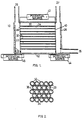
- Fig.1. is a section view of a simplified reaction chamber.
- Fig.2. is an end section view of part of the parallel array of tubes.
- Fig.3. is a section view of one such tube.
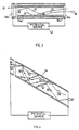
- Fig.4. is a section view of one such tube with an angle between electric field and tube axis.
- Fig.5. is a section view of an axial-flow reaction chamber with quad-symmetric tube mounting.
- Fig.6. is an end section view of part of the reaction chamber of Fig.5.
- an electrical device 10 for conversion of hydrocarbon molecular weights comprising a chamber 12 with walls constructed of glass, ceramic, or metal, with an inlet gas source 27, an outlet gas port 28, and a hydrogen outlet gas port 29.
- a chamber 12 with walls constructed of glass, ceramic, or metal, with an inlet gas source 27, an outlet gas port 28, and a hydrogen outlet gas port 29.
- an electrode 26 constructed of metal
- another electrode 22 constructed of metal or a suitable semiconducting material, which can serve as an electron source.
- a plurality 30 of tubular elements 32 which are joined together along their outer boundaries in an array so that the axis of each tubular element 32 is disposed parallel with each other.
- the tubular elements 32 are composed of appropriate glass, glass ceramic, or ceramic, and are bound together by direct fusion of their boundaries 36 as shown in Figure 2, or may also be bound together by means of a lower-softening-point glass applied at the boundaries 36.
- the interior of the tubes 32 are open cylinders 33 with interior surfaces 34 which have secondary-electron-emitting properties, and which have a zone of semiconducting material disposed just beneath the surfaces 34. Details of construction as described in U.S. Patent No. 3,260,876 (Manley et.al.) could be used, for example.
- the plurality 30 of tubular elements is coated with metallic electrode material 38 and 40 such as gold, nickel, or aluminum on the faces 38 and 40, with the open cylinders 33 penetrating the metallic electrode material.
- source 42 being connected between the faces 38 and 40 of the plurality 30 of tubular elements
- source 44 being connected from electrode 40 to electrode 26
- source 45 being connected from electrode 22 to electrode 38. Connection of these sources through a glass or ceramic chamber 12 is shown, whereas if a metallic chamber wall is used, separate insulative feed-through connections through the chamber wall would be required.
- the input gas such as methane CH4 or ethane C2H6 is admitted through port 27 into the chamber 10, with an ambient pressure of 133.3 x 10 ⁇ 6 to 133.3 Pa (10 ⁇ 6 to 1 Torr), for example.
- Diffusion of the gas into tubes 32 occurs, with some of the gas absorbing on the interior walls 34.
- Electrons originating either from the electron source 22, or from field emission from the edges of the metallic coating on face 38, or from cosmic rays, photoemission, or other natural sources, are accelerated along the length of the regions from source 22 to face 38, and onward towards face 40, striking the interior walls 34 enroute with substantial energies such as 10 to 100 electron volts.
- the range of energy values is adjustable with potential source 42.
- a sequence of cascading impacts takes place, which will be described below in detail, which removes hydrogen ions from the absorbed molecules, and allows hydrogen ions to move in the open cylinders 33 towards face 38, while at the same time allows negatively-charged hydrocarbon ions to move in the open cylinders 33 towards face 40.
- Subsequent impact of these hydrocarbon ions with other similar charged or neutral species causes combination into larger hydrocarbon molecules, which emerge from face 40 and are pumped away into outlet 28.
- the extracted hydrogen ions are carried by the electric field past face 38 where they combine with others of the same species and are pumped away into outlet 29.
- inlet methane will pass, by diffusion, directly into outlet port 28 and will be separated in subsequent condensation stages from the heavier hydrocarbon molecules formed by the device operation, after which the methane may be recirculated back into the inlet stream which feeds port 27.
- the methane molecules 55 may be considered to be absorbed upon the interior walls 34 in a strong, chemi-sorbed bond with silica or alumina, which pertains to a surface monolayer, and also in a weaker, multi-molecular-layer bond for additional molecules.
- an incident electron 51 with energy in the range 10 to 100 electron volts, a variety of processes are initiated. Some of the incident electron 51 energy goes to create secondary electrons 57 which are emitted from the wall 34 and which are accelerated in parabolic trajectories to perpetuate the process at the next impact with wall 34.
- Some of the incident electron 51 energy goes to separate a positive hydrogen ion 52 from an absorbed gas molecule 55, also creating a negatively-charged hydrocarbon ion 53, for example CH3 or CH2. Some of the incident electron 51 energy imparts sufficient kinetic energy to these ions 52 and 53 so that they depart from their surface creation site and are accelerated along the electric field direction, in parabolic paths. The hydrogen ion 52 will subsequently strike the wall 34 with sufficient energy to create secondary electrons which will contribute to the electron cascade required for the process; this is a positive ion feedback effect.
- the same impact of hydrogen ion 52 on wall 34 will also provide sufficient energy to disrupt the bonding of one or several gas molecules 55 absorbed at that site, thus creating more positive hydrogen ions and negative hydrocarbon ions which are released from that site and which are accelerated in opposite directions along the electric field direction, thus contributing to the process.
- the hydrocarbon ion 53 acquiring kinetic energy along it's parabolic path, strikes the wall 34 with energy sufficient to disrupt bonds of molecules 55 at the site of impact, permitting the formation of a carbon-carbon bond at that site, and thus the creation of a higher weight hydrocarbon molecule 56, which is shown in a negatively-charged ion state in Figure 3 as it emerges from face 40 of the tube.
- the higher-weight hydrocarbon may not leave the wall 34 immediately upon creation but will be dislodged by a subsequent electron or ion impact.
- the proper amount of charge required for electron current conservation at each impact site is provided by a small current flowing in a semiconducting layer just a few hundred Angstroms, or less, beneath the surface 34.
- a semiconducting layer just a few hundred Angstroms, or less, beneath the surface 34.
- Such a layer is easily formed by a prior high-temperature hydrogen reduction treatment of a lead-oxide aluminosilicate glass, for example.
- the parabolic paths of the electrons and of the ions, as described above, have a length which depends upon the electric field strength and also upon the initial kinetic energy of the particles and their direction of emission from the surface.
- the direction and initial kinetic energy of the particles will follow a statistical distribution function.
- Some of these particles will follow trajectories which are very long, enabling them to acquire hundreds of electron volts of kinetic energy. This may lead to complete removal of hydrogen upon impact, with deposition of elemental carbon. Although this may be removed by subsequent impacts, it would be useful to contrive both a lower and an upper limit upon the range of impact energies, and for this reason the geometry of inclined channel axes as shown in Fig. 4 will be discussed.
- an angle is introduced between the electric field and the tube axis, by preparing the bundle of tubes and then slicing the bundle at such an angle.
- Molecules 55 are not shown in Fig. 4 for purposes of reducing complexity, but are present along the wall 34.
- Impact of electron 51 creates hydrogen ion 52, hydrocarbon ion 53, and secondary electrons 58. Since there is an angle between electric field and tubular axis the length of the parabolic paths is sharply limited. For example, if the electric field is 10 volts per diameter, path lengths of three diameters or less, with resulting impact energies of 30 electron volts or less can be arranged. Many more impacts along the length are thus possible, creating larger molecular ions 57 and 56.
- the length of these tubes may extend from 10 diameters to 1000 diameters or more, and the combination of angle, electric field strength, length/diameter ratio, and total length can be chosen to optimize the conversion process in each particular case, depending upon input molecular species, flow rates, and desired spectrum of output molecular species,
- FIG. 5 One possible configuration is illustrated in Figure 5, where the plurality 30 of tubular elements 32 are disposed facing a central core region, with the most positive electrode 26 in the form of a rod at the center of the core region.
- the quad symmetry of this axial flow reactor is shown also in Figure 6, which illustrates that the electrode 26 provides the electric field to draw the larger negatively-charged molecules from the tubular elements exit surface electrodes 40.
- the potential sources 42, 44, 45 have deliberately been omitted from Figures 5 and 6 in the interest of drawing clarity, but are nonetheless essential to the operation and are connected as mentioned above.
- Inlet molecules from port 27 are converted in tubular elements 32 and higher-weight molecules are extracted at port 28, with hydrogen extracted at port 29.
- the flow of gas from inlet port 27 to outlet port 28 can be augmented by a magnetic field if desired to force converted charged molecules towards port 28.
- one configuration could be a magnetic field of cylindrical symmetry which would be produced by a large current in the rod 26, which would in such an instance penetrate the chamber wall 10 in two locations and which would be attached to a suitable current source.
- the magnetic force on the charged particles would be in the direction of the axial flow.
- Such a magnetic field would also extend into the tubular elements 32 where it would increase the number of collisions of charged particles with the walls and in certain circumstances improve the conversion efficiency.
Landscapes
- Chemical & Material Sciences (AREA)
- Organic Chemistry (AREA)
- Health & Medical Sciences (AREA)
- General Health & Medical Sciences (AREA)
- Toxicology (AREA)
- Chemical Kinetics & Catalysis (AREA)
- Inorganic Chemistry (AREA)
- Physical Or Chemical Processes And Apparatus (AREA)
- Production Of Liquid Hydrocarbon Mixture For Refining Petroleum (AREA)
- Hydrogen, Water And Hydrids (AREA)
Claims (16)
- Vorrichtung zur Umwandlung eines Moleküle mit einem ersten Molekulargewicht enthaltenden Gases in ein Moleküle mit einem zweiten Molekulargewicht enthaltendes Gas, welche eine Reaktionskammer (10) mit einem Gaseinlaß (27) und mindestens einem Gasauslaß (28, 29) aufweist, dadurch gekennzeichnet, daß die Reaktionskammer- mindestens eine Anordnung (30) von Reaktionsrohren aus Isoliermaterial (32) enthält, wobei jedes Rohrhat, wobei die Reaktionsrohre im wesentlichen parallel zu einander so angeordnet sind, daß das erste und das zweite Ende der Rohre eine erste bzw. eine zweite Fläche der Anordnung festlegen,(i) ein erstes und ein zweites offenes Ende,(ii) eine innere Oberfläche (34), die den Molekülen mit einem ersten Molekulargewicht ausgesetzt ist und Sekundärelektronen-abgebende Eigenschaften hat und eine Zone aus Halbleitermaterial direkt darunter aufweist, und(iii) eine Längsachse- eine auf der ersten Fläche der Anordnung angeordnete Elektrode (38), die mit den Halbleiterschichten an den ersten Enden der Reaktionsröhren verbunden ist;- eine auf der zweiten Fläche der Anordnung angeordnete zweite Elektrode (40), die mit den Halbleiterschichten an den zweiten Enden der Reaktionsröhren verbunden ist;und daß die Vorrichtung weiters- eine erste, äußere, elektrische Spannungsquelle (42) aufweist, welche(i) einen ersten, mit der ersten Elektrode (38) der Anordnung (30) verbundenen Pol und(ii) einen zweiten, mit der zweiten Elektrode (40) der Anordnung (30) verbundenen Pol und- eine Elektronenquelle, die sich an oder neben mindestens einer der Elektroden (38, 40) befindet,aufweist.
- Vorrichtung nach Anspruch 1, dadurch gekennzeichnet, daß die erste äußere elektrische Spannungsquelle (42) eine Gleichstromquelle ist, deren erster Pol negativ und deren zweiter Pol positiv ist, und daß die Vorrichtung weiters- eine dritte Elektrode (22), die neben der ersten Elektrode (38) der Anordnung (30) placiert ist und als Elektronenquelle fungiert, und- eine zweite äußere elektrische Spannungsquelle (45) aufweist, welcheaufweist, um eine Spannungsdifferenz zwischen der dritten und der ersten Elektrode zu gewährleisten, um Elektronen während ihres Durchgangs von der dritten zur ersten Elektrode zu beschleunigen.(i) einen ersten, mit der Elektrode (22) verbundenen Pol und(ii) einen zweiten, mit der ersten Elektrode (38) der Anordnung (30) verbundenen Pol
- Vorrichtung nach Anspruch 1, dadurch gekennzeichnet, daß die erste äußere elektrische Spannungsquelle (42) eine mit der Zeit. variierende Komponente und eine zusätzliche statische Komponente hat und daß die Vorrichtung weiters- eine dritte Elektrode (22), die neben der ersten Elektrode (38) der Anordnung (30) placiert ist und als Elektronenquelle fungiert, und- eine zweite äußere elektrische Spannungsquelle (45) aufweist, welcheum eine Spannungsdifferenz zwischen der dritten und der ersten Elektrode zu gewährleisten, um Elektronen während ihres Durchgangs von der dritten zur ersten Elektrode zu beschleunigen.(i) einen ersten, mit der Elektrode (22) verbundenen Pol und(ii) einen zweiten, mit der ersten Elektrode (38) der Anordnung (30) verbundenen Polaufweist,
- Vorrichtung nach den Ansprüchen 1-3, dadurch gekennzeichnet, daß sie weiters- eine vierte Elektrode (26), die neben der zweiten Elektrode (40) der Anordnung (30) placiert ist, und- eine dritte äußere elektrische Spannungsquelle (44) aufweist. welche(i) einen ersten, mit der vierten Elektrode (26) verbundenen Pol und(ii) einen zweiten, mit der zweiten Elektrode (40) der Anordnung (30) verbundenen Polaufweist.
- Vorrichtung nach den Ansprüchen 1-4, dadurch gekennzeichnet, daß die erste und die zweite Fläche der Anordnung im wesentlichen eben sind.
- Vorrichtung nach Anspruch 5, dadurch gekennzeichnet, daß die dritte Elektrode im wesentlichen parallel zur ersten Elektrode angeordnet ist.
- Vorrichtung nach Anspruch 5, dadurch gekennzeichnet, daß die vierte Elektrode im wesentlichen parallel zur zweiten Elektrode angeordnet ist.
- Vorrichtung nach den Ansprüchen 2-7, dadurch gekennzeichnet, daß die zweite äußere elektrische Spannungsquelle (45) eine Gleichstromquelle ist, deren erster Pol negativ und deren zweiter Pol positiv ist.
- Vorrichtung nach den Ansprüchen 1-8, dadurch gekennzeichnet, daß sie eine Anordnung von Reaktionsrohren und einen ersten und einen zweiten Gasauslaß (28, 29) hat; wobei der Gaseinlaß (27) und der erste Gasauslaß (28) neben der zweiten Fläche der Anordnung angeordnet sind; und der zweite Gasauslaß (29) sich neben der ersten Fläche der Anordnung befindet.
- Vorrichtung nach den Ansprüchen 1-8, dadurch gekennzeichnet, daß sie mindestens zwei Anordnungen von Reaktionsrohren hat, daß jede der Anordnungen eine Längsachse hat und daß diese Anordnungen um eine Mittelachse so angeordnet sind, daß die Längsachsen dieser Anordnungen orthogonal zur zentralen Achse hin gerichtet sind.
- Vorrichtung nach Anspruch 10, dadurch gekennzeichnet, daß sie eine lineare Elektrode (26 b, c) in der Nähe der Mittelachse und eine dritte äußere elektrische Spannungsquelle mit einem ersten Pol, der mit der linearen Elektrode verbunden ist, und einem zweiten Pol, der mit den zweiten Elektroden der Anordnungen verbunden ist, beinhaltet.
- Vorrichtung nach den Ansprüchen 1-11, dadurch gekennzeichnet, daß die dritte Elektrode (22) ein Material mit Elektronenemissionseigenschaften aufweist.
- Vorrichtung nach Anspruch 1, dadurch gekennzeichnet, daß die erste äußere elektrische Spannungsquelle eine mit der Zeit variierende Komponente und eine statische Komponente hat.
- Vorrichtung nach den Ansprüchen 1-13, dadurch gekennzeichnet, daß die erste und die zweite Fläche der Anordnung(en) im wesentlichen parallele Ebenen festlegen, die sich in einem Winkel befinden, der in bezug auf die Längsachsen der Reaktionsröhren in dieser Anordnung (diesen Anordnungen) nicht 90° ist.
- Verfahren zur Umwandlung einer ersten Substanz mit einem ersten Molekulargewicht in eine zweite Substanz mit einem zweiten Molekulargewicht in einer Reaktionszone, welche mindestens eine Anordnung von Reaktionsrohren mit im wesentlichen parallelen Längsachsen aufweist, die eine der ersten Substanz ausgesetzte innere Oberfläche haben, wobei diese innere Oberfläche eine Halbleiterschicht hat, und welches die folgenden Schritte aufweist:
Anlegen eines elektrischen Feldes mit einer signifikanten Komponente parallel zu den Längsachsen der Reaktionsrohre;
Einbringen der ersten Substanz in diese Reaktionsrohre, wobei die erste Substanz auf Elektronen, die durch das angelegte elektrische Feld beschleunigt sind, reagiert, um die zweite Substanz zu bilden; und
Sammeln der zweiten Substanz. - Verfahren nach Anspruch 15, dadurch gekennzeichnet, daß die erste Substanz einen Kohlenwasserstoff enthält.
Priority Applications (1)
| Application Number | Priority Date | Filing Date | Title |
|---|---|---|---|
| AT88909678T ATE104249T1 (de) | 1987-09-28 | 1988-09-17 | Elektrische anordnung zur umwandlung molekularer gewichte. |
Applications Claiming Priority (3)
| Application Number | Priority Date | Filing Date | Title |
|---|---|---|---|
| US10236187A | 1987-09-28 | 1987-09-28 | |
| US102361 | 1987-09-28 | ||
| PCT/US1988/003228 WO1989002868A1 (en) | 1987-09-28 | 1988-09-17 | Electrical device for conversion of molecular weights |
Publications (3)
| Publication Number | Publication Date |
|---|---|
| EP0393079A1 EP0393079A1 (de) | 1990-10-24 |
| EP0393079A4 EP0393079A4 (en) | 1990-12-05 |
| EP0393079B1 true EP0393079B1 (de) | 1994-04-13 |
Family
ID=22289444
Family Applications (1)
| Application Number | Title | Priority Date | Filing Date |
|---|---|---|---|
| EP88909678A Expired - Lifetime EP0393079B1 (de) | 1987-09-28 | 1988-09-17 | Elektrische anordnung zur umwandlung molekularer gewichte |
Country Status (10)
| Country | Link |
|---|---|
| EP (1) | EP0393079B1 (de) |
| JP (1) | JPH07108373B2 (de) |
| KR (1) | KR890701466A (de) |
| AU (2) | AU614796B2 (de) |
| CA (1) | CA1326647C (de) |
| DE (1) | DE3889124T2 (de) |
| DK (1) | DK78190A (de) |
| FI (1) | FI94842C (de) |
| LV (1) | LV10419B (de) |
| WO (1) | WO1989002868A1 (de) |
Families Citing this family (2)
| Publication number | Priority date | Publication date | Assignee | Title |
|---|---|---|---|---|
| US5141715A (en) * | 1991-04-09 | 1992-08-25 | University Of Alaska | Electrical device for conversion of molecular weights using dynodes |
| GB9317256D0 (en) * | 1993-08-19 | 1993-10-06 | Boc Group Plc | Molecular processes and apparatus therefore |
Family Cites Families (13)
| Publication number | Priority date | Publication date | Assignee | Title |
|---|---|---|---|---|
| US919445A (en) * | 1909-01-20 | 1909-04-27 | W W Gibbs | Ozonizer. |
| US1010777A (en) * | 1911-01-21 | 1911-12-05 | Ross Mortimer Leggett | Ozonizer. |
| US1037500A (en) * | 1911-11-23 | 1912-09-03 | Michael John Fritz | Ozonizer. |
| US2093619A (en) * | 1935-09-19 | 1937-09-21 | Electroaire Corp | Ozone producing apparatus |
| US2710835A (en) * | 1952-11-25 | 1955-06-14 | William A Pardey | Ozone making machine |
| GB1064074A (en) * | 1963-04-03 | 1967-04-05 | Mullard Ltd | Improvements in or relating to image intensifiers |
| US3565776A (en) * | 1968-09-26 | 1971-02-23 | John H Arff | Generator for producing allotropic oxygen |
| US3677931A (en) * | 1970-03-30 | 1972-07-18 | Louis Richard O Hare | Corona cell for nitrogen and other reactions |
| DE2165249C2 (de) * | 1971-12-29 | 1973-10-04 | Pavel Dr. 3213 Eldagsen Imris | Vorrichtung zur Herstellung von Ozon |
| US3942020A (en) * | 1974-12-09 | 1976-03-02 | Cubic Corporation | Corona discharge ozone generator |
| US4214995A (en) * | 1976-11-01 | 1980-07-29 | Saylor Laurence M | Ozone generator |
| CH660474A5 (de) * | 1984-06-27 | 1987-04-30 | Bbc Brown Boveri & Cie | Roehrenozonisator mit gekuehlter innenelektrode. |
| DE3521985A1 (de) * | 1985-05-21 | 1986-11-27 | BBC Aktiengesellschaft Brown, Boveri & Cie., Baden, Aargau | Ozonerzeuger |
-
1988
- 1988-09-17 EP EP88909678A patent/EP0393079B1/de not_active Expired - Lifetime
- 1988-09-17 AU AU26158/88A patent/AU614796B2/en not_active Ceased
- 1988-09-17 JP JP63508920A patent/JPH07108373B2/ja not_active Expired - Lifetime
- 1988-09-17 DE DE3889124T patent/DE3889124T2/de not_active Expired - Fee Related
- 1988-09-17 WO PCT/US1988/003228 patent/WO1989002868A1/en not_active Ceased
- 1988-09-26 CA CA000578388A patent/CA1326647C/en not_active Expired - Fee Related
-
1989
- 1989-05-27 KR KR1019890700939A patent/KR890701466A/ko active Granted
-
1990
- 1990-03-27 DK DK078190A patent/DK78190A/da not_active Application Discontinuation
- 1990-03-27 FI FI901522A patent/FI94842C/fi not_active IP Right Cessation
-
1991
- 1991-11-18 AU AU87957/91A patent/AU8795791A/en not_active Abandoned
-
1992
- 1992-12-23 LV LVP-92-414A patent/LV10419B/en unknown
Also Published As
| Publication number | Publication date |
|---|---|
| DK78190D0 (da) | 1990-03-27 |
| LV10419B (en) | 1995-10-20 |
| AU614796B2 (en) | 1991-09-12 |
| EP0393079A4 (en) | 1990-12-05 |
| FI94842B (fi) | 1995-07-31 |
| LV10419A (lv) | 1995-02-20 |
| DK78190A (da) | 1990-03-27 |
| JPH03501357A (ja) | 1991-03-28 |
| CA1326647C (en) | 1994-02-01 |
| DE3889124D1 (de) | 1994-05-19 |
| DE3889124T2 (de) | 1994-09-08 |
| WO1989002868A1 (en) | 1989-04-06 |
| KR890701466A (ko) | 1989-12-20 |
| FI94842C (fi) | 1995-11-10 |
| AU2615888A (en) | 1989-04-18 |
| FI901522A0 (fi) | 1990-03-27 |
| JPH07108373B2 (ja) | 1995-11-22 |
| AU8795791A (en) | 1992-02-06 |
| EP0393079A1 (de) | 1990-10-24 |
Similar Documents
| Publication | Publication Date | Title |
|---|---|---|
| KR950013066B1 (ko) | 분자량 전환 전기장치 | |
| EP0533907B1 (de) | Elektrische Anordnung zur Umwandlung molekularer Gewichte unter Verwendung von Dynoden | |
| US5019355A (en) | Electrical device for conversion of molecular weights | |
| Liu et al. | Photodetachment and photofragmentation studies of semiconductor cluster anions | |
| CN1195671C (zh) | 生产氢气的方法和装置 | |
| US7384619B2 (en) | Method for generating hydrogen from water or steam in a plasma | |
| Hosseinzadeh et al. | Upgrading of lignin-derived bio-oil in non-catalytic plasma reactor: effects of operating parameters on 4-methylanisole conversion | |
| Mitchell et al. | The recombination of electrons with complex molecular ions | |
| EP0393079B1 (de) | Elektrische anordnung zur umwandlung molekularer gewichte | |
| Kaldor et al. | The chemistry and physics of molecular surfaces | |
| Tanaka et al. | State selected ion–molecule reactions by a TESICO technique. X. O+ 2 (v)+ CH4 | |
| RU2040331C1 (ru) | Устройство для превращения молекул с одной молекулярной массой в молекулы с другой молекулярной массой | |
| Zarvin et al. | Jet plasma-chemical reactor for the conversion of methane: The use of clustering | |
| Behera et al. | Photo-induced molecular growth of benzonitrile in the gas phase | |
| WO2024009192A2 (en) | Method of homolytic and heterolytic cleavage in molecules of gases and liquids | |
| US20110011727A1 (en) | System and method for conversion of molecular weights of fluids | |
| Higgins | The Interactions of Small Molecules on Astrochemically Relevant Surfaces | |
| Sackinger et al. | Natural gas conversion to higher hydrocarbons using plasma interactions with surfaces. Final report | |
| Bernard | Unimolecular reactions of highly reactive species | |
| Jarrold et al. | Studies of the reactivity and collision induced dissociation of metal clusters: aluminum cluster ions, Aln+ (n= 3–26), with oxygen | |
| Curdes | A model for cluster formation from the inner track in the PDMS-process | |
| Kim | Mechanistic Studies of the Pyrolysis of Methylated Furans | |
| Kouprine | Thin film coating of nano-particles in a capacitively coupled RF discharge. |
Legal Events
| Date | Code | Title | Description |
|---|---|---|---|
| PUAI | Public reference made under article 153(3) epc to a published international application that has entered the european phase |
Free format text: ORIGINAL CODE: 0009012 |
|
| 17P | Request for examination filed |
Effective date: 19900328 |
|
| AK | Designated contracting states |
Kind code of ref document: A1 Designated state(s): AT BE CH DE FR GB IT LI LU NL SE |
|
| A4 | Supplementary search report drawn up and despatched |
Effective date: 19901018 |
|
| AK | Designated contracting states |
Kind code of ref document: A4 Designated state(s): AT BE CH DE FR GB IT LI LU NL SE |
|
| 17Q | First examination report despatched |
Effective date: 19910708 |
|
| RAP1 | Party data changed (applicant data changed or rights of an application transferred) |
Owner name: UNIVERSITY OF ALASKA |
|
| GRAA | (expected) grant |
Free format text: ORIGINAL CODE: 0009210 |
|
| AK | Designated contracting states |
Kind code of ref document: B1 Designated state(s): AT BE CH DE FR GB IT LI LU NL SE |
|
| REF | Corresponds to: |
Ref document number: 104249 Country of ref document: AT Date of ref document: 19940415 Kind code of ref document: T |
|
| REF | Corresponds to: |
Ref document number: 3889124 Country of ref document: DE Date of ref document: 19940519 |
|
| ITF | It: translation for a ep patent filed | ||
| ET | Fr: translation filed | ||
| EAL | Se: european patent in force in sweden |
Ref document number: 88909678.0 |
|
| PLBE | No opposition filed within time limit |
Free format text: ORIGINAL CODE: 0009261 |
|
| STAA | Information on the status of an ep patent application or granted ep patent |
Free format text: STATUS: NO OPPOSITION FILED WITHIN TIME LIMIT |
|
| 26N | No opposition filed | ||
| PGFP | Annual fee paid to national office [announced via postgrant information from national office to epo] |
Ref country code: LU Payment date: 19961001 Year of fee payment: 10 |
|
| PGFP | Annual fee paid to national office [announced via postgrant information from national office to epo] |
Ref country code: AT Payment date: 19961024 Year of fee payment: 9 |
|
| REG | Reference to a national code |
Ref country code: GB Ref legal event code: 732E |
|
| PGFP | Annual fee paid to national office [announced via postgrant information from national office to epo] |
Ref country code: FR Payment date: 19970820 Year of fee payment: 10 |
|
| PGFP | Annual fee paid to national office [announced via postgrant information from national office to epo] |
Ref country code: SE Payment date: 19970821 Year of fee payment: 10 Ref country code: NL Payment date: 19970821 Year of fee payment: 10 |
|
| PGFP | Annual fee paid to national office [announced via postgrant information from national office to epo] |
Ref country code: DE Payment date: 19970822 Year of fee payment: 10 |
|
| PGFP | Annual fee paid to national office [announced via postgrant information from national office to epo] |
Ref country code: CH Payment date: 19970828 Year of fee payment: 10 |
|
| PGFP | Annual fee paid to national office [announced via postgrant information from national office to epo] |
Ref country code: BE Payment date: 19970909 Year of fee payment: 10 |
|
| PG25 | Lapsed in a contracting state [announced via postgrant information from national office to epo] |
Ref country code: LU Free format text: LAPSE BECAUSE OF NON-PAYMENT OF DUE FEES Effective date: 19970917 Ref country code: AT Free format text: LAPSE BECAUSE OF NON-PAYMENT OF DUE FEES Effective date: 19970917 |
|
| PG25 | Lapsed in a contracting state [announced via postgrant information from national office to epo] |
Ref country code: SE Free format text: LAPSE BECAUSE OF NON-PAYMENT OF DUE FEES Effective date: 19980918 |
|
| PG25 | Lapsed in a contracting state [announced via postgrant information from national office to epo] |
Ref country code: LI Free format text: LAPSE BECAUSE OF NON-PAYMENT OF DUE FEES Effective date: 19980930 Ref country code: CH Free format text: LAPSE BECAUSE OF NON-PAYMENT OF DUE FEES Effective date: 19980930 Ref country code: BE Free format text: LAPSE BECAUSE OF NON-PAYMENT OF DUE FEES Effective date: 19980930 |
|
| BERE | Be: lapsed |
Owner name: DR. WILLIAM M. SACKINGER Effective date: 19980930 |
|
| PG25 | Lapsed in a contracting state [announced via postgrant information from national office to epo] |
Ref country code: NL Free format text: LAPSE BECAUSE OF NON-PAYMENT OF DUE FEES Effective date: 19990401 |
|
| REG | Reference to a national code |
Ref country code: CH Ref legal event code: PL |
|
| EUG | Se: european patent has lapsed |
Ref document number: 88909678.0 |
|
| PG25 | Lapsed in a contracting state [announced via postgrant information from national office to epo] |
Ref country code: FR Free format text: LAPSE BECAUSE OF NON-PAYMENT OF DUE FEES Effective date: 19990531 |
|
| NLV4 | Nl: lapsed or anulled due to non-payment of the annual fee |
Effective date: 19990401 |
|
| PG25 | Lapsed in a contracting state [announced via postgrant information from national office to epo] |
Ref country code: DE Free format text: LAPSE BECAUSE OF NON-PAYMENT OF DUE FEES Effective date: 19990701 |
|
| REG | Reference to a national code |
Ref country code: FR Ref legal event code: ST |
|
| PGFP | Annual fee paid to national office [announced via postgrant information from national office to epo] |
Ref country code: GB Payment date: 19990902 Year of fee payment: 12 |
|
| PG25 | Lapsed in a contracting state [announced via postgrant information from national office to epo] |
Ref country code: GB Free format text: LAPSE BECAUSE OF NON-PAYMENT OF DUE FEES Effective date: 20000917 |
|
| GBPC | Gb: european patent ceased through non-payment of renewal fee |
Effective date: 20000917 |
|
| PG25 | Lapsed in a contracting state [announced via postgrant information from national office to epo] |
Ref country code: IT Free format text: LAPSE BECAUSE OF NON-PAYMENT OF DUE FEES Effective date: 20050917 |