EP0392460A2 - Balayeur d'image en relief - Google Patents
Balayeur d'image en relief Download PDFInfo
- Publication number
- EP0392460A2 EP0392460A2 EP90106849A EP90106849A EP0392460A2 EP 0392460 A2 EP0392460 A2 EP 0392460A2 EP 90106849 A EP90106849 A EP 90106849A EP 90106849 A EP90106849 A EP 90106849A EP 0392460 A2 EP0392460 A2 EP 0392460A2
- Authority
- EP
- European Patent Office
- Prior art keywords
- gray
- level data
- edge signal
- edge
- linear
- Prior art date
- Legal status (The legal status is an assumption and is not a legal conclusion. Google has not performed a legal analysis and makes no representation as to the accuracy of the status listed.)
- Granted
Links
Images


Classifications
-
- G—PHYSICS
- G06—COMPUTING; CALCULATING OR COUNTING
- G06K—GRAPHICAL DATA READING; PRESENTATION OF DATA; RECORD CARRIERS; HANDLING RECORD CARRIERS
- G06K7/00—Methods or arrangements for sensing record carriers, e.g. for reading patterns
- G06K7/10—Methods or arrangements for sensing record carriers, e.g. for reading patterns by electromagnetic radiation, e.g. optical sensing; by corpuscular radiation
- G06K7/14—Methods or arrangements for sensing record carriers, e.g. for reading patterns by electromagnetic radiation, e.g. optical sensing; by corpuscular radiation using light without selection of wavelength, e.g. sensing reflected white light
- G06K7/1404—Methods for optical code recognition
- G06K7/146—Methods for optical code recognition the method including quality enhancement steps
- G06K7/1465—Methods for optical code recognition the method including quality enhancement steps using several successive scans of the optical code
-
- G—PHYSICS
- G06—COMPUTING; CALCULATING OR COUNTING
- G06K—GRAPHICAL DATA READING; PRESENTATION OF DATA; RECORD CARRIERS; HANDLING RECORD CARRIERS
- G06K7/00—Methods or arrangements for sensing record carriers, e.g. for reading patterns
- G06K7/10—Methods or arrangements for sensing record carriers, e.g. for reading patterns by electromagnetic radiation, e.g. optical sensing; by corpuscular radiation
- G06K7/14—Methods or arrangements for sensing record carriers, e.g. for reading patterns by electromagnetic radiation, e.g. optical sensing; by corpuscular radiation using light without selection of wavelength, e.g. sensing reflected white light
-
- G—PHYSICS
- G06—COMPUTING; CALCULATING OR COUNTING
- G06V—IMAGE OR VIDEO RECOGNITION OR UNDERSTANDING
- G06V10/00—Arrangements for image or video recognition or understanding
- G06V10/10—Image acquisition
- G06V10/12—Details of acquisition arrangements; Constructional details thereof
- G06V10/14—Optical characteristics of the device performing the acquisition or on the illumination arrangements
- G06V10/147—Details of sensors, e.g. sensor lenses
Definitions
- This invention relates to a relief image scanner for reading or capturing a relief image from the surface of an information-carrying medium such as a plastic card or metal plate.
- Plastic cards such as credit cards, bank cards, and hospital patient cards are often embossed with raised letters and numbers giving a name, identification number, account number, or other information. Alternatively, such information may be stamped into the card, the letters and numbers being formed as depressions in the surface of the card. It is often desirable to transfer the information to an electronic data-processing system, for which purpose the surface of the card must be scanned by a device capable of detecting embossed or stamped patterns. (Such patterns will be referred to generally as relief patterns below.) At the same time it may be desirable to capture information printed or otherwise provided on flat portions of the card, such as the card owner's signature and photograph. (Such information will generally be referred to as printed information below.)
- Prior-art apparatus for capturing images of relief patterns comprises a television camera and four light sources.
- the four light sources which are disposed around the four sides of the card, illuminate the card from four directions in succession.
- each light source is turned on, the relief casts shadows which are detected by the television camera and stored in a memory.
- the four shadow images are then combined by OR logic, yielding a total image of the relief.
- This apparatus is unsatisfactory due to its large size, since it requires four separate light sources.
- the television camera is also large and expensive.
- a further problem is that since the angles of illumination vary at different positions on the card, the shadows are of different lengths, which distorts the image.
- the captured image shows only the outlines of the relief. If the relief comprises depressions, outline images are formed when the depressions are so wide that they are not entirely filled by the shadows. If the relief comprises raised characters, then outline images are always formed, and there is a tendency for the outlines of adjacent characters to run together. Such outline images look unnatural to the eye, and are difficult for computer-based character recognition systems to identify accurately.
- the card also contains printed information or a printed background pattern, which may be mistaken by the television camera for part of the relief pattern.
- An object of the present invention is accordingly to provide a compact, low-cost relief image scanner.
- Another object is to capture relief images without distortion.
- Still another object is to capture both relief images and printed images.
- Yet another object is to distinguish relief images from printed images.
- a relief image scanner has an optical scanning means for illuminating each of a succession of linear areas on the surface of an information-carrying medium from a first direction and from a second direction, and converting the reflected light to an analog electrical signal.
- An A/D converter converts the analog electrical signal to first gray-level data during illumination from the first direction and to second gray-level data during illumination from the second direction.
- a ternarizing means compares first gray-level data with second gray-level data, produces a first edge signal if the first gray-level data exceeds the second gray-level data by a certain threshold, and produces a second edge signal if the second gray-level data exceeds the first gray-level data by this threshold.
- a connecting means sets binary output data to a first state when a first edge signal is produced and to a second state when a second edge signal is produced, the binary output data not being changed when neither the first edge signal nor the second edge signal is produced.
- the relief image scanner may also have a skeletonizing means, disposed between the ternarizing means and the connecting means, for selecting one of a series of consecutive first edge signals or consecutive second edge signals and furnishing only the selected edge signals to the connecting means.
- the relief image scanner may furthermore have a binarizing means for converting gray-level data to binary output data, and a switch for directing gray-level data from the A/D converter either to the ternarizing means or to the binarizing means.
- a novel relief image scanner for capturing images of both relief and printed information from the surface of an information-carrying medium will be described below with reference to the drawings.
- the information-carrying medium will be shown as a plastic card embossed with raised letters, but it will be apparent that the invention is equally applicable to media with stamped relief patterns formed by depressions.
- the relief image scanner has an optical scanning means 2 which illuminates a plastic card 4 from two directions and converts the reflected light to an analog electrical signal A.
- the optical scanning means 2 comprises a first linear light source 6, which illuminates a linear area on the plastic card 4 from a first direction, and a second linear light source 8, which illuminates the same linear area from a second direction.
- the first linear light source 6 and the second linear light source 8 are disposed parallel to each other and parallel to the surface of the plastic card 4, the linear light sources and the linear area they illuminate extending perpendicular to the page in the drawing.
- a line sensor 10 disposed parallel to the two light sources, at a position substantially midway between the two light sources as seen from the surface of the plastic card 4.
- the line sensor 10 comprises a row of transducers 11, the row extending perpendicular to the page in the drawing, each transducer 11 converting optical input to electrical output.
- the line sensor 10 may be a semiconductor charge-coupled device in which incident light generates electrical charges that accumulate in the transducers 11 in amounts proportional to the brightness level. After accumulation, the charges can be sequentially read out from the transducers 11 as a voltage signal.
- a rod lens 12 comprising a row of parallel lens elements, the row again extending perpendicular to the page in the drawing, is disposed between the line sensor 10 and the surface of the plastic card 4 to convey light reflected from the linear area to the transducers 11.
- a linear area on the surface of the plastic card 4 can be considered to comprise a row of mutually adjacent pixels, corresponding to the lens elements in the rod lens 12 and the transducers 11 in the line sensor 10. Light reflected from a single pixel is received at a single transducer 11 and converted to a single electrical output.
- the word pixel will also be used below to refer to an arbitrary position in the row, i.e. to a specific transducer 11 and the part of the image seen by this transducer 11.
- the optical scanning means 2 is electrically coupled to an analog-to-digital (A/D) converter 16 which receives the analog electrical signal A and converts it to gray-level data B.
- the A/D converter 16 may be, for example, an eight-bit A/D converter producing eight-bit data B representing voltage levels of the analog electrical signal A. Gray-level data produced when the first linear light source 6 is on and the second linear light source 8 is off will be referred to as first gray-level data B1. Gray-level data produced when the first linear light source 6 is off and the second linear light source 8 is on will be referred to as second gray-level data B2.
- the gray-level data B are sent from the A/D converter 16 to a switch 18, which directs the gray-level data to a binarizing means 20 or a ternarizing means 22.
- the binarizing means 20, which is used in capturing images of printed information, comprises a gamma correction means 24 and a dithering means 26.
- the gamma correction means 24 receives the gray-level data B, modifies the gray-level data B according to a gamma curve which will be shown later, and produces gamma-corrected gray-level data G.
- the ternarizing means 22 which is used in capturing relief images, receives gray-level data B comprising first gray-level data B1 and second gray-level data B2 from the A/D converter 16 via the switch 18.
- the ternarizing means 22 has a first line memory 28 for storing first gray-level data B1 from a single linear area on the surface of the plastic card 4, and a second line memory 30 for storing second gray-level data B2 from the same linear area.
- a subtraction means 32 subtracts data stored in a location in the second line memory 30 from data stored at the corresponding location in the first line memory 28 to produce a difference value D.
- a comparison means 34 compares the difference D and its additive inverse -D with a threshold S. If D > S, the comparison means 34 produces a first edge signal E. If -D > S, the comparison means 34 produces a second edge signal F.
- the plastic card 4 moves in the direction of the arrow in Fig. 1, so that a succession of mutually adjacent linear areas on the surface of the plastic card 4 are illuminated. An image of the entire surface of the plastic card 4 can thus be captured.
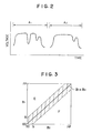
- the operation performed by the ternarizing means 22 is illustrated graphically in Fig. 3.
- the vertical axis represents the first gray-level data B1 for an arbitrary pixel, and the horizontal axis represents the second gray-level data B2 for the same pixel, these two data being stored at corresponding locations in the first and second line memories 28 and 30 and subtracted to obtain the difference D.
- B1 - B2 D > S and a first edge signal E is produced.
- B2 - B1 -D > S and a second edge signal F is produced.
- the skeletonizing means 36 performs the above operation twice separately for each pixel: once to test the N bits stored for that pixel in the first N-line memory 38, to decide whether to produce the signal E′, and once to test the N bits stored for that pixel in the second N-line memory 40, to decide whether to produce the signal F′.
- the ternarizing means 22 operates on the difference between the first and second gray-level data B1 and B2, the image represented by the binary output data Y represents only the relief pattern on the plastic card 4. It does not include printed information, which reflects the light from the first and second light sources 6 and 8 equally. Since all areas on the plastic card 4 are illuminated from the same angles by the first linear light source 6 and the second linear light source 8, the image is free of distortion. Moreover, both embossed and stamped relief patterns are captured accurately; in either case the image fills areas between substantially the midlines of complementary pairs of edges. False outline images are not produced as in the prior art.
- both the first linear light source 6 and the second linear light source 8 can be switched on to reduce shadows cast by relief.
- Each linear area on the plastic card 4 is scanned just once, producing one line of gray-level data B.
- the switch 18 is set to the lower position in Fig. 1 to direct the gray-level data B to the gamma correction means 24.
- the operation of the gamma correction means 24 is illustrated in Fig. 7.
- the input gray-level data B shown as eight-bit data, are converted to six-bit gamma-corrected gray-level data G according to a gamma curve 52.
- the purpose of this correction is to compensate for non-linearity in the response of the line sensor 10.
- the dithering means 26 converts the gamma-corrected gray-level data G to binary output data H in which "1" and "0" bits represent black and white dots, different gray levels being represented by different densities of black dots. More specifically, the dithering means 26 compares the gamma-corrected gray-level data G with a dither matrix comprising a plurality of different threshold values. Further details of the dithering process will be omitted since they are well known. Dithering enables the binary output data H to represent not only printed lines, letters and numerals but also halftone pictorial information such as a photograph of the card owner.
- the binary output data Y and/or H can be printed directly as bit-mapped images, or supplied to a character-recognition system that recognizes characters such as the letter B at (d) in Fig. 6 and converts such characters to computer codes. Relief and printed information can thus be conveniently transferred from a card to a printed receipt, or to a computerized data-processing system.
- the novel relief image scanner is smaller in size and lower in cost, since it requires only two light sources instead of four and only a simple line sensor instead of a large, expensive television camera.
- the image is free of distortion because the angles of illumination are the same for all areas.
- the image is also free of outline distortion, and relief can be accurately distinguished from printed patterns.
- the dithering means 26 can be omitted and the output of the gamma correction means 24 used directly. If it is only necessary to capture relief images, the switch 18 and the binarizing means 20 can be omitted, the A/D converter 16 then being coupled directly to the ternarizing means 22. It is also possible to omit the skeletonizing means 36 and couple the ternarizing means 22 directly to the connecting means 44, although the captured relief image will then be shifted to one side by an amount equivalent to half the height of the relief. It is furthermore possible to scan the information-carrying medium by moving the optical scanning means past the medium, instead of moving the medium past the optical scanning means as shown in Fig. 1.
Landscapes
- Engineering & Computer Science (AREA)
- Physics & Mathematics (AREA)
- Theoretical Computer Science (AREA)
- General Health & Medical Sciences (AREA)
- General Physics & Mathematics (AREA)
- Health & Medical Sciences (AREA)
- Toxicology (AREA)
- Electromagnetism (AREA)
- Artificial Intelligence (AREA)
- Computer Vision & Pattern Recognition (AREA)
- Quality & Reliability (AREA)
- Vascular Medicine (AREA)
- Multimedia (AREA)
- Image Input (AREA)
- Character Input (AREA)
Applications Claiming Priority (4)
| Application Number | Priority Date | Filing Date | Title |
|---|---|---|---|
| JP92373/89 | 1989-04-12 | ||
| JP1092373A JPH0816919B2 (ja) | 1989-04-12 | 1989-04-12 | 凹凸パターン読取装置 |
| JP1181910A JPH0346079A (ja) | 1989-07-13 | 1989-07-13 | イメージ情報読取装置 |
| JP181910/89 | 1989-07-13 |
Publications (3)
| Publication Number | Publication Date |
|---|---|
| EP0392460A2 true EP0392460A2 (fr) | 1990-10-17 |
| EP0392460A3 EP0392460A3 (fr) | 1992-05-20 |
| EP0392460B1 EP0392460B1 (fr) | 1994-12-21 |
Family
ID=26433809
Family Applications (1)
| Application Number | Title | Priority Date | Filing Date |
|---|---|---|---|
| EP90106849A Expired - Lifetime EP0392460B1 (fr) | 1989-04-12 | 1990-04-10 | Balayeur d'image en relief |
Country Status (3)
| Country | Link |
|---|---|
| US (1) | US5050231A (fr) |
| EP (1) | EP0392460B1 (fr) |
| DE (1) | DE69015238T2 (fr) |
Cited By (1)
| Publication number | Priority date | Publication date | Assignee | Title |
|---|---|---|---|---|
| EP1543990A3 (fr) * | 2003-12-17 | 2006-04-26 | Stralfors Ab | Méthode et moyens de contrôle d'un procédé de production de cartes. |
Families Citing this family (11)
| Publication number | Priority date | Publication date | Assignee | Title |
|---|---|---|---|---|
| US5299268A (en) * | 1991-11-27 | 1994-03-29 | At&T Bell Laboratories | Method for detecting the locations of light-reflective metallization on a substrate |
| US5428210A (en) * | 1992-01-10 | 1995-06-27 | National Bancard Corporation | Data card terminal with embossed character reader and signature capture |
| JP2910534B2 (ja) * | 1993-11-18 | 1999-06-23 | ノーリツ鋼機株式会社 | 写真フィルム用コード情報読取装置 |
| US5771107A (en) * | 1995-01-11 | 1998-06-23 | Mita Industrial Co., Ltd. | Image processor with image edge emphasizing capability |
| US7028899B2 (en) * | 1999-06-07 | 2006-04-18 | Metrologic Instruments, Inc. | Method of speckle-noise pattern reduction and apparatus therefore based on reducing the temporal-coherence of the planar laser illumination beam before it illuminates the target object by applying temporal phase modulation techniques during the transmission of the plib towards the target |
| US6628808B1 (en) | 1999-07-28 | 2003-09-30 | Datacard Corporation | Apparatus and method for verifying a scanned image |
| AU2003223406A1 (en) * | 2002-07-08 | 2004-01-23 | Veritec, Inc. | Method for reading a symbol having encoded information |
| TW200407030A (en) * | 2002-10-30 | 2004-05-01 | Umax Data Systems Inc | Image compensation method |
| EP1439517A1 (fr) * | 2003-01-10 | 2004-07-21 | Deutsche Thomson-Brandt Gmbh | Appareil et procédé de traitement de données vidéo destinées à être visualisées sur écran |
| US7593591B2 (en) * | 2005-08-05 | 2009-09-22 | Seiko Epson Corporation | Method and apparatus for increasing contrast in a digital image |
| US20070108288A1 (en) * | 2005-11-16 | 2007-05-17 | Caskey Gregory T | Method and apparatus for novel reading of surface structure bar codes |
Citations (6)
| Publication number | Priority date | Publication date | Assignee | Title |
|---|---|---|---|---|
| US3619569A (en) * | 1970-07-15 | 1971-11-09 | Rca Corp | Optical card-reading apparatus |
| DE2160179A1 (de) * | 1970-12-03 | 1972-06-08 | Tno | Verfahren und Vorrichtung zur Erkennung von mit Reliefzeichen versehenen Dokumenten |
| US3838347A (en) * | 1971-03-24 | 1974-09-24 | Zellweger Uster Ag | Apparatus for transforming a deteriorated input signal into a binary signal |
| FR2470999A1 (fr) * | 1979-11-28 | 1981-06-12 | Despres Robert | Dispositif pour la lecture d'informations mises en memoire sur un support |
| DE3630202A1 (de) * | 1986-09-04 | 1988-03-10 | Karl F Zimmer Kg | Elektro-optische abtasteinrichtung fuer einen strichcode, bei welchem die striche als erhabene stege ausgebildet sind |
| FR2607288A1 (fr) * | 1986-11-20 | 1988-05-27 | Oki Electric Ind Co Ltd | Procede et dispositif pour le traitement de cartes imprimees en relief |
Family Cites Families (4)
| Publication number | Priority date | Publication date | Assignee | Title |
|---|---|---|---|---|
| US3774015A (en) * | 1971-05-18 | 1973-11-20 | Amp Inc | Optical reader for an embossed card |
| JPS60144884A (ja) * | 1983-12-31 | 1985-07-31 | Nippon Steel Corp | 打刻印字の検出方法 |
| US4628195A (en) * | 1984-03-09 | 1986-12-09 | American Magnetics Corporation | Credit card security system |
| US4878125A (en) * | 1987-01-08 | 1989-10-31 | Canon Kabushiki Kaisha | Method and apparatus for image processing with fed-back error correction |
-
1990
- 1990-04-10 DE DE69015238T patent/DE69015238T2/de not_active Expired - Lifetime
- 1990-04-10 EP EP90106849A patent/EP0392460B1/fr not_active Expired - Lifetime
- 1990-04-11 US US07/507,468 patent/US5050231A/en not_active Expired - Lifetime
Patent Citations (6)
| Publication number | Priority date | Publication date | Assignee | Title |
|---|---|---|---|---|
| US3619569A (en) * | 1970-07-15 | 1971-11-09 | Rca Corp | Optical card-reading apparatus |
| DE2160179A1 (de) * | 1970-12-03 | 1972-06-08 | Tno | Verfahren und Vorrichtung zur Erkennung von mit Reliefzeichen versehenen Dokumenten |
| US3838347A (en) * | 1971-03-24 | 1974-09-24 | Zellweger Uster Ag | Apparatus for transforming a deteriorated input signal into a binary signal |
| FR2470999A1 (fr) * | 1979-11-28 | 1981-06-12 | Despres Robert | Dispositif pour la lecture d'informations mises en memoire sur un support |
| DE3630202A1 (de) * | 1986-09-04 | 1988-03-10 | Karl F Zimmer Kg | Elektro-optische abtasteinrichtung fuer einen strichcode, bei welchem die striche als erhabene stege ausgebildet sind |
| FR2607288A1 (fr) * | 1986-11-20 | 1988-05-27 | Oki Electric Ind Co Ltd | Procede et dispositif pour le traitement de cartes imprimees en relief |
Non-Patent Citations (1)
| Title |
|---|
| PROCEEDINGS OF THE 8TH INTERNATIONAL CONFERENCE ON PATTERN RECOGNITION, Paris, 27th - 31st October 1986, pages 995-997, IEEE Computer Society; YUN XIA: "A new thinning algorithm for binary images" * |
Cited By (1)
| Publication number | Priority date | Publication date | Assignee | Title |
|---|---|---|---|---|
| EP1543990A3 (fr) * | 2003-12-17 | 2006-04-26 | Stralfors Ab | Méthode et moyens de contrôle d'un procédé de production de cartes. |
Also Published As
| Publication number | Publication date |
|---|---|
| DE69015238T2 (de) | 1995-05-04 |
| DE69015238D1 (de) | 1995-02-02 |
| EP0392460A3 (fr) | 1992-05-20 |
| US5050231A (en) | 1991-09-17 |
| EP0392460B1 (fr) | 1994-12-21 |
Similar Documents
| Publication | Publication Date | Title |
|---|---|---|
| US6264105B1 (en) | Bar code reader configured to read fine print barcode symbols | |
| KR960008379B1 (ko) | 다수의 휘도준위를 갖는 화상의 이진화 처리방법 | |
| US5050231A (en) | Relief image scanner | |
| US5617484A (en) | Image binarizing apparatus | |
| US4345314A (en) | Dynamic threshold device | |
| US6058225A (en) | Information reproduction system which feedback controls a pulse width of light source pulses during manual scanning of an optically readable dot code | |
| JPS62200488A (ja) | 光学的文字読取装置 | |
| US5563713A (en) | Image processing method and apparatus with adding of a white outline to an outline of a character image | |
| US4408343A (en) | Image enhancement for optical character readers | |
| US5034825A (en) | High quality image scanner | |
| EP0504576A2 (fr) | Lecteur de documents | |
| JP3358133B2 (ja) | 画像処理装置 | |
| JPH06203206A (ja) | カードのイメージ読み取り装置 | |
| US7050621B2 (en) | Specified pattern detecting apparatus | |
| CA2215555A1 (fr) | Dispositif de traitement d'images | |
| JP3303990B2 (ja) | 画像信号処理装置 | |
| JP3210378B2 (ja) | 画像入力装置 | |
| JPH08227455A (ja) | 点字読取装置 | |
| JPH0346079A (ja) | イメージ情報読取装置 | |
| JP2000003441A (ja) | 指紋画像処理方法および指紋画像処理装置 | |
| JPH0341869B2 (fr) | ||
| JPH0119192B2 (fr) | ||
| JPS63211480A (ja) | 光学文字読取装置 | |
| JPH10143632A (ja) | エンボス読み取り装置 | |
| JPH0816919B2 (ja) | 凹凸パターン読取装置 |
Legal Events
| Date | Code | Title | Description |
|---|---|---|---|
| PUAI | Public reference made under article 153(3) epc to a published international application that has entered the european phase |
Free format text: ORIGINAL CODE: 0009012 |
|
| AK | Designated contracting states |
Kind code of ref document: A2 Designated state(s): DE FR GB |
|
| PUAL | Search report despatched |
Free format text: ORIGINAL CODE: 0009013 |
|
| AK | Designated contracting states |
Kind code of ref document: A3 Designated state(s): DE FR GB |
|
| 17P | Request for examination filed |
Effective date: 19920924 |
|
| 17Q | First examination report despatched |
Effective date: 19940505 |
|
| GRAA | (expected) grant |
Free format text: ORIGINAL CODE: 0009210 |
|
| AK | Designated contracting states |
Kind code of ref document: B1 Designated state(s): DE FR GB |
|
| ET | Fr: translation filed | ||
| REF | Corresponds to: |
Ref document number: 69015238 Country of ref document: DE Date of ref document: 19950202 |
|
| PLBE | No opposition filed within time limit |
Free format text: ORIGINAL CODE: 0009261 |
|
| STAA | Information on the status of an ep patent application or granted ep patent |
Free format text: STATUS: NO OPPOSITION FILED WITHIN TIME LIMIT |
|
| 26N | No opposition filed | ||
| REG | Reference to a national code |
Ref country code: GB Ref legal event code: IF02 |
|
| PGFP | Annual fee paid to national office [announced via postgrant information from national office to epo] |
Ref country code: DE Payment date: 20090402 Year of fee payment: 20 Ref country code: FR Payment date: 20090417 Year of fee payment: 20 |
|
| PGFP | Annual fee paid to national office [announced via postgrant information from national office to epo] |
Ref country code: GB Payment date: 20090408 Year of fee payment: 20 |
|
| REG | Reference to a national code |
Ref country code: GB Ref legal event code: PE20 Expiry date: 20100409 |
|
| PG25 | Lapsed in a contracting state [announced via postgrant information from national office to epo] |
Ref country code: GB Free format text: LAPSE BECAUSE OF EXPIRATION OF PROTECTION Effective date: 20100409 |
|
| PG25 | Lapsed in a contracting state [announced via postgrant information from national office to epo] |
Ref country code: DE Free format text: LAPSE BECAUSE OF EXPIRATION OF PROTECTION Effective date: 20100410 |