EP0392153B1 - Dishwashing machine - Google Patents
Dishwashing machine Download PDFInfo
- Publication number
- EP0392153B1 EP0392153B1 EP90102677A EP90102677A EP0392153B1 EP 0392153 B1 EP0392153 B1 EP 0392153B1 EP 90102677 A EP90102677 A EP 90102677A EP 90102677 A EP90102677 A EP 90102677A EP 0392153 B1 EP0392153 B1 EP 0392153B1
- Authority
- EP
- European Patent Office
- Prior art keywords
- spraying
- arm
- dishwashing machine
- washing
- crockery
- Prior art date
- Legal status (The legal status is an assumption and is not a legal conclusion. Google has not performed a legal analysis and makes no representation as to the accuracy of the status listed.)
- Expired - Lifetime
Links
- 238000004851 dishwashing Methods 0.000 title claims description 19
- 238000005406 washing Methods 0.000 claims description 36
- 238000005507 spraying Methods 0.000 claims description 33
- 239000012530 fluid Substances 0.000 claims description 8
- 238000004519 manufacturing process Methods 0.000 description 3
- 238000010276 construction Methods 0.000 description 2
- 238000004140 cleaning Methods 0.000 description 1
- 235000019646 color tone Nutrition 0.000 description 1
- 239000003599 detergent Substances 0.000 description 1
- XLYOFNOQVPJJNP-UHFFFAOYSA-N water Substances O XLYOFNOQVPJJNP-UHFFFAOYSA-N 0.000 description 1
Images

Classifications
-
- A—HUMAN NECESSITIES
- A47—FURNITURE; DOMESTIC ARTICLES OR APPLIANCES; COFFEE MILLS; SPICE MILLS; SUCTION CLEANERS IN GENERAL
- A47L—DOMESTIC WASHING OR CLEANING; SUCTION CLEANERS IN GENERAL
- A47L15/00—Washing or rinsing machines for crockery or tableware
- A47L15/14—Washing or rinsing machines for crockery or tableware with stationary crockery baskets and spraying devices within the cleaning chamber
- A47L15/18—Washing or rinsing machines for crockery or tableware with stationary crockery baskets and spraying devices within the cleaning chamber with movably-mounted spraying devices
- A47L15/22—Rotary spraying devices
- A47L15/23—Rotary spraying devices moved by means of the sprays
Definitions
- the present invention relates to a dishwashing machine having a rectangular base, with one dimension of the washing chamber substantially bigger than the other, comprising all the elements as known for its operation.
- the present invention relates to a dishwashing machine with one dimension of the washing chamber substantially bigger than the other, eg. with its depth bigger than its width.
- the problem characterizing the machines of this type is that the rectangular shape of the washing chamber, seen in plan view, does not let the spraying arms to reach evenly each part of the chamber internal space, thus affecting the washing results of the crockery.
- the document EP-A-0 278 371 describes a dishwashing machine having a rectangular base, which in its front view shows a convex line along the washing chamber sides near the lower arm.
- a dishwashing machine with a washing chamber and means for spraying a washing fluid within said chamber, comprising an element showing at least one spraying hole, said element being mounted in a way to present combined movements of rotation and revolution, so that said hole is moved along a continuous epicyclical path meandering within internal and external limits.
- the described machine requires a complicated mechanical arrangement.
- the purpose of the present invention is to provide an improved dishwashing machine, relatively simple and reasonable in cost, which nevertheless allows an even washing result all over the washing chamber without any of the inconveniences mentioned above.
- a dishwashing machine having a rectangular base and comprising all elements as known for its operation, including a washing chamber, upper and lower spraying arms, and upper and lower baskets, to hold the crockery, characterised in that one dimension of the rectangular base is substantially bigger than the other, the spraying arms rotate around fixed axes which are located in the washing chamber in a non-coaxial manner, and are out of alignment at least with respect to the bigger dimension of the chamber, so that one of the two spraying arms cooperates with the other arm by spraying also the basket associated to said other arm.
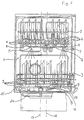
- Fig. 1 where a side sectional view of the dishwashing machine achieved according to the invention is shown, number 1 indicates the washing chamber of the dishwasher containing two baskets to hold the crockery, namely an upper one 2 and a lower one 3. Beneath said baskets 2 and 3 there are two spraying arms, 4 and 5 respectively, provided with outlet holes for the washing fluid; said holes are obtained on the upper surface 6, on the lower surface 7 and on the ends 8 of the upper spraying arm 4, and likewise on 9, 10, 11 of the lower spraying arm 5.
- spraying arms 4 and 5 are located on two different axes 12 and 13, respectively.
- Fig. 2 showing a top view of the dishwasher without the baskets 2 and 3, gives a better vie of how axes 12 and 13 of the upper arm 4 and lower arm 5 are differing; moreover, the circumferences 14 and 15 generated by the vertices of said arms 4 and 5 are clearly visible.
- Fig. 2 reporting the reference numbers of Fig. 1, brings to evidence the rectangular base of the washing chamber 1, where numbers 16a and 16b indicate the side walls, 17 the front door and 18 the back wall; an arm 19 on the side wall is foreseen to support the spraying arm 4.
- the spraying arms 4 and 5 can achieve a good washing result of the crockery placed on the baskets 2 and 3 through the jets of the washing fluid coming out of the holes 6, 7, 8, 9, 11. This result is obtained by the non-coaxial arrangement of said spraying arms, which covers the spaces of the washing chamber 1 otherwise difficult to reach. Washing action is also increased by the special presence of the holes 7, through which the detergent fluid coming from the upper spraying arm 4 is spraying onto the crockery placed on the lower basket 3, whereas the holes 10 are intended for the cleaning of the filter located in the base 20 of the dishwashing machine through the action of the spraying jets coming from the lower spraying arm 5.
- a further version may consist of a different arrangement of the crockery supports in the baskets.
- a part of the lower basket 3 could have its supports arranged with a different orientation form the one described in Fig. 1, selecting an inclination angle that allows an excellent spraying on the crockery from both spraying arms.
- orientation of the crockery supports in the lower basket 3 be selected in such a way that on the crockery touched by the jets of washing fluid no shaded areas are left in respect to the upper arm 4 and the lower one 5.
Landscapes
- Washing And Drying Of Tableware (AREA)
Description
- The present invention relates to a dishwashing machine having a rectangular base, with one dimension of the washing chamber substantially bigger than the other, comprising all the elements as known for its operation.
- To uniform the style of composable kitchen elements, the manufacturers of household appliances endeavour to introduce such products on the market that may comply more and more with the users' requirements. This is why at retailer shops it is possible to see more and more household appliances of different size, different colour tones, featuring details of undoubtful esthetic taste or bearing glamorous fashion names that increase the value of appliances.
- The present invention relates to a dishwashing machine with one dimension of the washing chamber substantially bigger than the other, eg. with its depth bigger than its width. The problem characterizing the machines of this type is that the rectangular shape of the washing chamber, seen in plan view, does not let the spraying arms to reach evenly each part of the chamber internal space, thus affecting the washing results of the crockery.
- As known, the document EP-A-0 278 371 describes a dishwashing machine having a rectangular base, which in its front view shows a convex line along the washing chamber sides near the lower arm.
- This achievement has the purpose of providing a lower arm that is longer than the upper one, which would not be achievable should the chamber sides be perpendicular all over their length, as in this case the motion of the lower arm would be hindered by said chamber walls. Therefore, it is the aim of said European Patent application to have the lower arm increasing, through its diameter, the washing capacity in the washing chamber depth, since an arm with a diameter slightly smaller than the width of said washing chamber would not achieve it.
- However, said Patent application entails considerable problems both of constructive and cost-effect nature, among which the most significant and obvious ones are as follows:
- construction of the washing chamber causes considerable manufacturing difficulties due to its special configuration;
- the manufacturing costs for the washing chamber are higher if compared to standard machines;
- the small space increase achievable through a convex configuration is not such yet to allow construction of a very deep washing chamber without falling back into the known inconveniences for this type of dishwashing machines.
- There is also known from FR-A- 2 243 671 a dishwashing machine with a washing chamber and means for spraying a washing fluid within said chamber, comprising an element showing at least one spraying hole, said element being mounted in a way to present combined movements of rotation and revolution, so that said hole is moved along a continuous epicyclical path meandering within internal and external limits. The described machine requires a complicated mechanical arrangement.
- Therefore the purpose of the present invention is to provide an improved dishwashing machine, relatively simple and reasonable in cost, which nevertheless allows an even washing result all over the washing chamber without any of the inconveniences mentioned above.
- To achieve said purpose it is the aim of the present invention to realize a dishwashing machine having a rectangular base and comprising all elements as known for its operation, including a washing chamber, upper and lower spraying arms, and upper and lower baskets, to hold the crockery, characterised in that one dimension of the rectangular base is substantially bigger than the other, the spraying arms rotate around fixed axes which are located in the washing chamber in a non-coaxial manner, and are out of alignment at least with respect to the bigger dimension of the chamber, so that one of the two spraying arms cooperates with the other arm by spraying also the basket associated to said other arm.
- Further aims and advantages of the present invention are clearly described in the following detailed description and annexed drawings, where:
- Fig. 1 is a side sectional view of a dishwasher achieved according to the present invention;
- Fig. 2 is a top view of the dishwasher according to the present invention, showing specifically the spraying arms.
- In Fig. 1, where a side sectional view of the dishwashing machine achieved according to the invention is shown, number 1 indicates the washing chamber of the dishwasher containing two baskets to hold the crockery, namely an upper one 2 and a lower one 3. Beneath said
baskets 2 and 3 there are two spraying arms, 4 and 5 respectively, provided with outlet holes for the washing fluid; said holes are obtained on theupper surface 6, on thelower surface 7 and on theends 8 of theupper spraying arm 4, and likewise on 9, 10, 11 of thelower spraying arm 5. - As shown in the figure, spraying
arms different axes - Fig. 2, showing a top view of the dishwasher without the
baskets 2 and 3, gives a better vie of howaxes upper arm 4 andlower arm 5 are differing; moreover, thecircumferences said arms - It will be noted that the two rotating
axes arms circumferences arms - Fig. 2, reporting the reference numbers of Fig. 1, brings to evidence the rectangular base of the washing chamber 1, where
numbers arm 19 on the side wall is foreseen to support the sprayingarm 4. - According to the present invention, the spraying
arms baskets 2 and 3 through the jets of the washing fluid coming out of theholes holes 7, through which the detergent fluid coming from the upper sprayingarm 4 is spraying onto the crockery placed on the lower basket 3, whereas theholes 10 are intended for the cleaning of the filter located in thebase 20 of the dishwashing machine through the action of the spraying jets coming from thelower spraying arm 5. - The characteristics of the dishwashing machine described above are clearly illustrated in the description and annexed drawings.
- Likewise also the advantages of the improved dishwashing maschine according to the present invention are clear.
- Specifically, they are represented by:
- the possibility of increasing the depth of the washing chamber 1, however without detriment for the washing results;
- its simple achievement in view of the manufacturing procedures;
- its low cost as the standard shape of the washing chamber does not need to be changed.
- It is obvious that for the man skilled in the art many other changes to the dishwashing machine described by way of example are possible, however without departing from the scope of the innovating criteria inherent to the present invention as defined in the appended claims.
- By way of example it is suggested the possibility of a different arrangement of the upper spraying
arm 4 instead of locating it on anarm 19, eg. to receive the washing fluid from above though keeping its non-coaxial position against thelower spraying arm 5. - A further version may consist of a different arrangement of the crockery supports in the baskets. For instance, a part of the lower basket 3 could have its supports arranged with a different orientation form the one described in Fig. 1, selecting an inclination angle that allows an excellent spraying on the crockery from both spraying arms. To this purpose it is suggested that orientation of the crockery supports in the lower basket 3 be selected in such a way that on the crockery touched by the jets of washing fluid no shaded areas are left in respect to the
upper arm 4 and the lower one 5.
Claims (6)
- Dishwashing machine having a rectangular base and comprising all elements as known for its operation, including a washing chamber (1), upper and lower spraying arms (4, 5), and upper and lower baskets (2, 3), to hold the crockery, characterised in that one dimension of the rectangular base is substantially bigger than the other, the spraying arms (4, 5) rotate around fixed axes (12, 13) which are located in the washing chamber (1) in a non-coaxial manner, and are out of alignment at least with respect to the bigger dimension of the chamber (1), so that one (4) of the two spraying arms cooperates with the other arm (5) by spraying also the basket (3) associated to said other arm (5).
- Dishwashing machine according to claim 1, characterised in that the two rotating axes (12, 13) are out of alignment also with respect to the smaller dimension of the chamber (1).
- Dishwashing machine according to claim 1 or 2, characterised in that said spraying arms (4, 5) are provided with a set of holes (6, 7, 8, 9, 10, 11) for the spraying of the crockery placed in the baskets (2, 3), said holes being so arranged to cover the space of the washing chamber (1) in a substantially even manner with the jets of washing fluid.
- Dishwashing machine according to any of the preceding claims, characterised in that some holes (7) are provided in the lower surface of the upper spraying arm (4) so as to cooperate in the washing of the crockery arranged in the lower basket (3).
- Dishwashing machine according to any of the preceding claims, characterised in that said lower spraying arm (5) is provided with some holes (10) in its lower surface.
- Dishwashing machine according to any of the preceding claims, characterised in that the crockery supports in the lower basket (3) are oriented in such a way that on the crockery reached by the jets of the washing fluid no shaded areas are left in respect to the upper arm (4) and the lower arm. (5).
Applications Claiming Priority (2)
| Application Number | Priority Date | Filing Date | Title |
|---|---|---|---|
| IT8967077A IT1232575B (en) | 1989-02-13 | 1989-02-13 | DISHWASHER MACHINE PERFECTED |
| IT6707789 | 1989-02-13 |
Publications (2)
| Publication Number | Publication Date |
|---|---|
| EP0392153A1 EP0392153A1 (en) | 1990-10-17 |
| EP0392153B1 true EP0392153B1 (en) | 1994-10-05 |
Family
ID=11299385
Family Applications (1)
| Application Number | Title | Priority Date | Filing Date |
|---|---|---|---|
| EP90102677A Expired - Lifetime EP0392153B1 (en) | 1989-02-13 | 1990-02-12 | Dishwashing machine |
Country Status (4)
| Country | Link |
|---|---|
| EP (1) | EP0392153B1 (en) |
| DE (1) | DE69013040T2 (en) |
| ES (1) | ES2062122T3 (en) |
| IT (1) | IT1232575B (en) |
Family Cites Families (8)
| Publication number | Priority date | Publication date | Assignee | Title |
|---|---|---|---|---|
| US2960990A (en) * | 1956-01-26 | 1960-11-22 | Whirlpool Co | One level dishwasher |
| GB858151A (en) * | 1958-09-09 | 1961-01-11 | Insulex Ltd | Improvements in or relating to apparatus for washing dishes and other utensils |
| DE1183214B (en) * | 1961-12-13 | 1964-12-10 | Siemens Elektrogeraete Gmbh | Dishwasher |
| US3285779A (en) * | 1964-11-17 | 1966-11-15 | King Fifth Wheel Company | Dishwashing apparatus |
| GB1286820A (en) * | 1968-12-12 | 1972-08-23 | Hoover Ltd | Improvements relating to dish washing machines |
| US3876148A (en) * | 1973-09-13 | 1975-04-08 | Gen Electric | Dishwasher having epicyclic spray system |
| FR2508304B1 (en) * | 1981-06-30 | 1986-02-07 | Esswein Sa | DISHWASHER WITH AUTOMATICALLY CLEANED RECYCLING FILTER |
| IT211716Z2 (en) * | 1987-02-02 | 1989-04-07 | Zanussi Elettrodomestici | WASHING TANK FOR DISHWASHER. |
-
1989
- 1989-02-13 IT IT8967077A patent/IT1232575B/en active
-
1990
- 1990-02-12 DE DE69013040T patent/DE69013040T2/en not_active Expired - Lifetime
- 1990-02-12 EP EP90102677A patent/EP0392153B1/en not_active Expired - Lifetime
- 1990-02-12 ES ES90102677T patent/ES2062122T3/en not_active Expired - Lifetime
Also Published As
| Publication number | Publication date |
|---|---|
| ES2062122T3 (en) | 1994-12-16 |
| DE69013040D1 (en) | 1994-11-10 |
| DE69013040T2 (en) | 1995-01-26 |
| IT8967077A0 (en) | 1989-02-13 |
| EP0392153A1 (en) | 1990-10-17 |
| IT1232575B (en) | 1992-02-26 |
Similar Documents
| Publication | Publication Date | Title |
|---|---|---|
| US5351837A (en) | Dishwasher rack assembly with fold down combs | |
| US3496949A (en) | Dishwasher with multiple spray arm | |
| USD424257S (en) | Combined dish washing machine and drying machine | |
| US20020148494A1 (en) | Dishwasher with auxiliary basket | |
| US20210393108A1 (en) | Configurable lower rack for dishwasher | |
| WO2000049935A1 (en) | Dishwashing machine basket with foldable dish holder racks | |
| US3451557A (en) | Removable article supporting device for automatic dishwasher rack | |
| EP0143754A1 (en) | Dishwasher basket | |
| KR20220059163A (en) | Rack assembly and dish washer comprising the same | |
| EP0392153A1 (en) | Dishwashing machine | |
| KR20230063760A (en) | Dish washer | |
| EP0448531B1 (en) | Device for a dishwasher | |
| US7426933B2 (en) | Dishwasher with kinetic energy water distribution system | |
| DE59404797D1 (en) | Household appliance, such as a dishwasher or washing machine | |
| EP4397228A1 (en) | Dishwasher | |
| JPH11332809A (en) | Dish washer | |
| US4815487A (en) | Wash tub for a dishwasher | |
| GB2238234A (en) | Domestic dishwasher with cutlery support means | |
| EP0400467B1 (en) | Tank for household appliance, particularly for washing machine | |
| KR200271812Y1 (en) | A table having a roast machine for skewered stuff | |
| KR200332899Y1 (en) | The ceiling plate of an electric steamer | |
| KR960008432Y1 (en) | Washing structure in washing machines for crockery | |
| KR20230133660A (en) | Dish washer | |
| JPH0418524Y2 (en) | ||
| JP3043630U (en) | Combination rack |
Legal Events
| Date | Code | Title | Description |
|---|---|---|---|
| PUAI | Public reference made under article 153(3) epc to a published international application that has entered the european phase |
Free format text: ORIGINAL CODE: 0009012 |
|
| AK | Designated contracting states |
Kind code of ref document: A1 Designated state(s): DE ES FR GB |
|
| 17P | Request for examination filed |
Effective date: 19910416 |
|
| 17Q | First examination report despatched |
Effective date: 19930503 |
|
| GRAA | (expected) grant |
Free format text: ORIGINAL CODE: 0009210 |
|
| AK | Designated contracting states |
Kind code of ref document: B1 Designated state(s): DE ES FR GB |
|
| REF | Corresponds to: |
Ref document number: 69013040 Country of ref document: DE Date of ref document: 19941110 |
|
| REG | Reference to a national code |
Ref country code: ES Ref legal event code: FG2A Ref document number: 2062122 Country of ref document: ES Kind code of ref document: T3 |
|
| ET | Fr: translation filed | ||
| PLBE | No opposition filed within time limit |
Free format text: ORIGINAL CODE: 0009261 |
|
| STAA | Information on the status of an ep patent application or granted ep patent |
Free format text: STATUS: NO OPPOSITION FILED WITHIN TIME LIMIT |
|
| 26N | No opposition filed | ||
| REG | Reference to a national code |
Ref country code: GB Ref legal event code: IF02 |
|
| PGFP | Annual fee paid to national office [announced via postgrant information from national office to epo] |
Ref country code: ES Payment date: 20090205 Year of fee payment: 20 |
|
| PGFP | Annual fee paid to national office [announced via postgrant information from national office to epo] |
Ref country code: DE Payment date: 20090227 Year of fee payment: 20 |
|
| PGFP | Annual fee paid to national office [announced via postgrant information from national office to epo] |
Ref country code: GB Payment date: 20090223 Year of fee payment: 20 |
|
| PGFP | Annual fee paid to national office [announced via postgrant information from national office to epo] |
Ref country code: FR Payment date: 20090219 Year of fee payment: 20 |
|
| REG | Reference to a national code |
Ref country code: GB Ref legal event code: PE20 Expiry date: 20100211 |
|
| REG | Reference to a national code |
Ref country code: ES Ref legal event code: FD2A Effective date: 20100213 |
|
| PG25 | Lapsed in a contracting state [announced via postgrant information from national office to epo] |
Ref country code: GB Free format text: LAPSE BECAUSE OF EXPIRATION OF PROTECTION Effective date: 20100211 |
|
| PG25 | Lapsed in a contracting state [announced via postgrant information from national office to epo] |
Ref country code: ES Free format text: LAPSE BECAUSE OF EXPIRATION OF PROTECTION Effective date: 20100213 |
|
| PG25 | Lapsed in a contracting state [announced via postgrant information from national office to epo] |
Ref country code: DE Free format text: LAPSE BECAUSE OF EXPIRATION OF PROTECTION Effective date: 20100212 |