EP0390988A1 - Air extractor arrangements - Google Patents
Air extractor arrangements Download PDFInfo
- Publication number
- EP0390988A1 EP0390988A1 EP89303344A EP89303344A EP0390988A1 EP 0390988 A1 EP0390988 A1 EP 0390988A1 EP 89303344 A EP89303344 A EP 89303344A EP 89303344 A EP89303344 A EP 89303344A EP 0390988 A1 EP0390988 A1 EP 0390988A1
- Authority
- EP
- European Patent Office
- Prior art keywords
- pop
- out section
- arrangement
- housing
- fixed housing
- Prior art date
- Legal status (The legal status is an assumption and is not a legal conclusion. Google has not performed a legal analysis and makes no representation as to the accuracy of the status listed.)
- Granted
Links
- 238000001125 extrusion Methods 0.000 description 7
- 229910052782 aluminium Inorganic materials 0.000 description 6
- 239000004411 aluminium Substances 0.000 description 6
- XAGFODPZIPBFFR-UHFFFAOYSA-N aluminium Chemical compound [Al] XAGFODPZIPBFFR-UHFFFAOYSA-N 0.000 description 4
- 238000010411 cooking Methods 0.000 description 4
- 230000000694 effects Effects 0.000 description 4
- 238000009423 ventilation Methods 0.000 description 4
- 229910001209 Low-carbon steel Inorganic materials 0.000 description 2
- 150000001398 aluminium Chemical class 0.000 description 2
- 238000010586 diagram Methods 0.000 description 2
- 238000013022 venting Methods 0.000 description 2
- 229920006074 Nylatron® Polymers 0.000 description 1
- 238000010276 construction Methods 0.000 description 1
- 230000001419 dependent effect Effects 0.000 description 1
- 238000001914 filtration Methods 0.000 description 1
- 238000009434 installation Methods 0.000 description 1
- 238000000034 method Methods 0.000 description 1
- 230000000737 periodic effect Effects 0.000 description 1
- 230000002093 peripheral effect Effects 0.000 description 1
- 230000000717 retained effect Effects 0.000 description 1
- 238000005096 rolling process Methods 0.000 description 1
Images


Classifications
-
- F—MECHANICAL ENGINEERING; LIGHTING; HEATING; WEAPONS; BLASTING
- F24—HEATING; RANGES; VENTILATING
- F24C—DOMESTIC STOVES OR RANGES ; DETAILS OF DOMESTIC STOVES OR RANGES, OF GENERAL APPLICATION
- F24C15/00—Details
- F24C15/20—Removing cooking fumes
- F24C15/2042—Devices for removing cooking fumes structurally associated with a cooking range e.g. downdraft
-
- F—MECHANICAL ENGINEERING; LIGHTING; HEATING; WEAPONS; BLASTING
- F24—HEATING; RANGES; VENTILATING
- F24C—DOMESTIC STOVES OR RANGES ; DETAILS OF DOMESTIC STOVES OR RANGES, OF GENERAL APPLICATION
- F24C15/00—Details
- F24C15/20—Removing cooking fumes
- F24C15/2078—Removing cooking fumes movable
Definitions
- This invention relates to air extractor arrangements and is especially applicable to such arrangements for use in domestic kitchens.
- U.S. Patent No. 4,501,260 there is disclosed a cooktop ventilation system in which a motor driven vent intake element is provided which can be raised above the level of the cooktop to a venting position and which can be retracted within the cooktop when not in use.
- a motor driven vent intake element is provided which can be raised above the level of the cooktop to a venting position and which can be retracted within the cooktop when not in use.
- the system disclosed in this patent has advantages over previously known ventilation systems, it requires the vent intake element to be mounted on a mechanically complex scissor mechanism with guide rails, and also requires a mechanically complex motor driven crank wheel arrangement for raising and lowering the vent intake element.
- the system disclosed requires a blower to be mounted at the exhaust end of a venting duct which extends out of the unit e.g. at a wall or roof outlet, which means that the unit is not wholly self-contained.
- an air extractor arrangement comprising a fixed housing, an extractor fan coupled to said fixed housing, a pop-out section having an air-intake, said fixed housing and said pop-out section being telescopically disposed one within the other, and a linear bearing provided between said fixed housing and said pop-out section by means of which said pop-out section is slidingly attached to said housing.
- the pop-out section will be disposed within the fixed housing.
- the fixed housing and the pop-out section are each of generally rectangular form, the pop-out section being movable from a first position in which it is substantially contained within said housing to a second position in which it projects from said housing.
- said pop-out section is movable vertically between said first position and said second position.
- means conveniently in the form of a tensator spring, will be provided for causing said pop-out section to be moved automatically from said first position to said second position, and it will also be arranged that said pop-out section is moved manually between said second position and said first position.
- latch means will be provided for retaining said pop-out section in said first position, it being arranged that when said latch means is operated, said pop-out section is caused to be moved automatically from said first position to said second position.
- motor drive means conveniently in the form of a motor and worm drive cable arrangement, will be provided for causing said pop-out section to be moved automatically between said first position and said second position.
- said extractor fan is coupled to said fixed housing via a plenum chamber, in which case the linear bearing may be arranged to extend into said plenum chamber.
- the air extractor arrangement will be adapted to be substantially flush fitted in a kitchen work-top.
- FIGs. 1 and 2 there is shown an air extractor arrangement which is designed to be flush fitted in a kitchen work-top, typically either behind a cooking hob or perhaps to one side of a cooking hob.
- the air extractor arrangement could be fitted as an integral part of a cooking hob.
- the air extractor arrangement shown in Figs. 1 and 2 comprises a fixed housing 1 which is of generally rectangular form and may typically be made of mild steel.
- the housing 1 is of open top construction with an outwardly extending peripheral flange 2 by means of which it is supported in a suitable slot 3 provided in a work-top 4 (Fig. 2).
- the bottom of the housing 1 is partially closed off and is provided with a rectangular hole 5 having outwardly extending flanges 6.
- To the bottom of the housing 1 and to the flanges 6 is secured a plenum chamber 7, and to the plenum chamber 7 is secured an extractor fan 8 by means of which air is sucked out of the housing 1 to be fed to a suitable outlet (not shown) via output duct 9.
- a pop-out section 10 also of generally rectangular form and also typically made of mild steel.
- the pop-out section 10 is made a reasonably close sliding fit in housing 1 to minimise the flow of air between them. This air flow may be further minimised using conventional "draught-excluding" techniques.
- the pop-out section 10 is provided with a centrally located vertical channel 11 in which is disposed a linear bearing in the form of a ball-bearing type slide bar assembly by means of which the pop-out section 10 is slidingly attached to the housing 1.
- one bar 12 of the slide bar assembly is affixed to the inside of the housing 1 and the other bar 13 is affixed in the channel 11 to the pop-out section 10.
- the pop-out section 10 is vertically movable between a first position in which the pop-out section 10 is fully contained within the housing 1 as depicted in full lines in Fig. 2, and a second position in which it projects from the housing 1 as depicted in dashed lines in Fig. 2. It will be noted that the bottom end of the slide bar assembly 12,13 extends into the plenum chamber 7 in order to reduce the overall height of the arrangement.
- the pop-out section 10 is open at the bottom and is provided with a cut-away top and upper-front part over which fits an air intake grille 14 (shown in side section in Fig. 2).
- the front part 15 of the grille 14 is provided with a plurality of horizontally disposed slots 16 through which, when the pop-out section 10 is in its upper (second) position as shown in dashed lines in Fig. 2, air is drawn under the influence of extractor fan 8.
- filter elements 17 which are disposed in the pop-out section 10.
- the grille 14 is removable from the top of the pop-out section 10 thereby providing access to the filter element(s) 17.
- the pop-out section 10 In its normal out-of-use position, the pop-out section 10 is contained within the housing 1 and it is retained in this position by means of a spring biassed solenoid operated latch 18 which extends through the housing 1 and into a slot 19 in the pop-out section 10.
- a tensator spring 20 consisting of a tightly coiled spring strip 21 is provided carried on a bracket 22 mounted on the outside of the housing 1, the end of the spring strip 21 passing through a slot 23 in the housing 1 and extending downwards between the housing 1 and the pop-out section 10 and being fixed to the underside of the pop-out section 10 by means of screw 24.
- the tensator spring 20 provides an upward bias on the pop-out section 10 so that when the latch 18 is operated, it is withdrawn from the slot 19 in the pop-out section 10 so allowing the pop-out section 10 to be raised under the action of the tensator spring 20. Movement of the pop-out section 10 back to its out-of-use (first) position, is effected by manually pressing the pop-out section 10 downwards, against the action of the tensator spring 20 until the latch 18 engages the slot 19 in the pop-out section 10.
- FIGs. 4 to 7 of the accompanying drawings there is shown an air extractor arrangement which is similar to that which has been described with reference to Figs. 1 to 3, but which has been modified to provide for fully automatic operation of the pop-out section 10.
- parts of the air extractor arrangement which correspond to like parts in the embodiment of Figs. 1 to 3 have been accorded the same reference numerals.
- the arrangement shown in Fig. 4 comprises a fixed housing 1 of generally rectangular form, to the bottom of which is fixed a plenum chamber 7.
- a fan 8 is secured to the plenum chamber 7, the fan being provided with an output duct 9.
- a pop-out section 10 which is slidingly supported in the housing 1 by means of a linear bearing in the form of a slide bar assembly comprising a slide bar 12 secured to the inside of the housing 1 and a slide bar 13 secured to the pop-out section 10.
- a motor driven cable arrangement is provided.
- This comprises a motor and worm drive unit 30 which is attached to the outside of the plenum chamber 7 from which extends a cable 31, typically a Bowden cable, contained within a cable guide tube 32.
- the other end of cable 31 and cable guide tube 32 is coupled to the slide bar 12 which is secured to the inside of the housing 1 and is used to effect movement of the slide bar 13 which is secured to the pop-out section 10.
- Fig. 5 of the drawings there is shown a cross-sectional view on the lines B-B of the motor and worm drive unit 30 of Fig. 1.
- the cable 31 has secured to it a helically wound wire 34 which forms a worm gear which co-operates with a gear wheel 35 such that when the gear wheel 35 is rotated by a motor (not shown), the cable 31 is moved axially within the cable guide tube 32. This axial movement of the cable 31 is used to effect raising and lowering of the pop-out section 10.
- Fig. 6 of the drawings there is shown a cross-sectional view on the lines A-A of Fig. 1 showing how the axial movement of the cable 31 is used to raise and lower the pop-out section 10.
- part of the side of the housing 1 is shown to which the slide bar 12 in the form of an aluminium extrusion is secured.
- the channel 11 in the side of the pop-out section 10 is also shown, in which is secured the other slide bar 13 of the slide bar assembly.
- Between the slide bars 12 and 13 are disposed a plurality of ball bearing type rolling elements 36 by means of which the slide bar 13 is slidingly supported on the slide bar 12.
- the aluminium extrusion slide bar 12 is provided with a vertical bore 37 in which the free end of the cable 31 is disposed, and in the lower part of the bore 37 is secured the free end of the cable guide tube 32.
- a driving spiggot 38 which extends outwards laterally through a vertical channel 39 in the side of the aluminium extrusion 12, the channel 39 extending from the bore 37 to the outer edge of the extrusion 12.
- the driving spiggot 38 extends into a slot (not shown) in the slide bar 13 and in the pop-out section 10 so that vertical movement of the cable 31 causes the driving spiggot 38 and thus the pop-out section 10 to be moved vertically.
- Control of the upwards and downwards movement of the pop-out section 10 may be achieved by respective "UP” and “DOWN” push buttons which control the operation and direction of the motor of the motor and worm drive unit 30.
- the pop-out section 10 is power driven, the sliding friction between the slide bars 12 and 13 is no longer critical and it may be possible to use a sliding block arrangement in order to reduce costs.
- a sliding block arrangement in order to reduce costs.
- the slide bar 12 in the form of an aluminium extrusion is secured to the side of the housing 1.
- the aluminium extrusion is provided with a vertical channel 40, of generally "T" shaped cross-section in which is slidingly disposed a sliding block 41, typically of NYLATRON, the sliding block 41 extending out of the channel 40 and being secured to the pop-out section 10.
- the aluminium extrusion 12 is also provided with a vertical bore 42 in which the cable 31 is disposed, and the cable 31 is provided with a driving spiggot 43, similar to the driving spiggot 38 of Fig. 6, which extends into a slot in the sliding block 42.
- a driving spiggot 43 similar to the driving spiggot 38 of Fig. 6, which extends into a slot in the sliding block 42.
- the air extractor arrangements described with reference to the accompanying drawings when used in conjunction with an associated cooking hob, may be effected in a number of different ways. For example, it may be arranged that whenever a hob hot plate or burner is energised, the air extractor arrangement is automatically brought into use. In this case the speed of the extractor fan 8 may be fixed or may be varied by means of a separate "speed" control. Alternatively, a separate control may be provided to activate the air extractor arrangement, possibly in conjunction with an extractor fan speed control.
Landscapes
- Engineering & Computer Science (AREA)
- Chemical & Material Sciences (AREA)
- Combustion & Propulsion (AREA)
- Mechanical Engineering (AREA)
- General Engineering & Computer Science (AREA)
- Structures Of Non-Positive Displacement Pumps (AREA)
- Ventilation (AREA)
- Air-Flow Control Members (AREA)
Abstract
Description
- This invention relates to air extractor arrangements and is especially applicable to such arrangements for use in domestic kitchens.
- In U.S. Patent No. 4,501,260 there is disclosed a cooktop ventilation system in which a motor driven vent intake element is provided which can be raised above the level of the cooktop to a venting position and which can be retracted within the cooktop when not in use. Whilst the system disclosed in this patent has advantages over previously known ventilation systems, it is relatively expensive to implement in that it requires the vent intake element to be mounted on a mechanically complex scissor mechanism with guide rails, and also requires a mechanically complex motor driven crank wheel arrangement for raising and lowering the vent intake element. In addition, the system disclosed requires a blower to be mounted at the exhaust end of a venting duct which extends out of the unit e.g. at a wall or roof outlet, which means that the unit is not wholly self-contained.
- Whilst the fully automatic system which is disclosed in U.S. Patent No. 4,501,260 may be suitable for use with relatively expensive cooktop installations, it is felt that there is a need for an alternative, less expensive, self-contained, cooktop ventilation system which is not necessarily fully automatic e.g. the system may be semi-automatic in that the vent intake element may be raised automatically but lowered manually. The fact that the vent intake element may be lowered manually places severe constraints on the way it is slidably supported in the unit in that it must respond to pressure applied at the extreme ends of the element without jamming the element, and it is unlikely that the scissor mechanism disclosed in the aforesaid U.S. Patent would be suitable.
- It is an object of the present invention to provide an air extractor arrangement especially in the form of a cooktop ventilation system which is provided with an improved arrangement for supporting and driving the vent intake element, enabling either semi-automatic or fully automatic operation to be achieved.
- According to the present invention there is provided an air extractor arrangement comprising a fixed housing, an extractor fan coupled to said fixed housing, a pop-out section having an air-intake, said fixed housing and said pop-out section being telescopically disposed one within the other, and a linear bearing provided between said fixed housing and said pop-out section by means of which said pop-out section is slidingly attached to said housing.
- In a preferred arrangement the pop-out section will be disposed within the fixed housing.
- In carrying out the invention it may be arranged that the fixed housing and the pop-out section are each of generally rectangular form, the pop-out section being movable from a first position in which it is substantially contained within said housing to a second position in which it projects from said housing.
- Preferably, said pop-out section is movable vertically between said first position and said second position.
- In one arrangement according to the invention, means, conveniently in the form of a tensator spring, will be provided for causing said pop-out section to be moved automatically from said first position to said second position, and it will also be arranged that said pop-out section is moved manually between said second position and said first position.
- Conveniently, latch means will be provided for retaining said pop-out section in said first position, it being arranged that when said latch means is operated, said pop-out section is caused to be moved automatically from said first position to said second position.
- In another arrangement according to the invention, motor drive means, conveniently in the form of a motor and worm drive cable arrangement, will be provided for causing said pop-out section to be moved automatically between said first position and said second position.
- Preferably it may be arranged that said extractor fan is coupled to said fixed housing via a plenum chamber, in which case the linear bearing may be arranged to extend into said plenum chamber.
- In an especially preferred form of the invention the air extractor arrangement will be adapted to be substantially flush fitted in a kitchen work-top.
- Some exemplary embodiments of the invention will now be described reference being made to the accompanying drawings, in which:
- Fig. 1, is an exploded view depicting the main parts of a first air extractor arrangement in accordance with the present invention designed for semi-automatic operation;
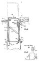
- Fig. 2, is a partial side view of the air extractor arrangement of Fig. 1 fitted in a kitchen work-top;
- Fig. 3, is a circuit diagram relevant to the electrical operation of the arrangement of Fig. 2;
- Fig. 4, is a partially cut-away front view of a second air extractor arrangement in accordance with the present invention designed for fully automatic operation;
- Fig. 5, is a cross-sectional view on the lines B-B of Fig. 4;
- Fig. 6, is a cross-sectional view on the lines A-A of Fig.4; and
- Fig. 7, is a cross-sectional view on the lines A-A of Fig. 4 of an alternative form of linear bearing.
- In Figs. 1 and 2 there is shown an air extractor arrangement which is designed to be flush fitted in a kitchen work-top, typically either behind a cooking hob or perhaps to one side of a cooking hob. Alternatively, the air extractor arrangement could be fitted as an integral part of a cooking hob.
- The air extractor arrangement shown in Figs. 1 and 2 comprises a
fixed housing 1 which is of generally rectangular form and may typically be made of mild steel. Thehousing 1 is of open top construction with an outwardly extendingperipheral flange 2 by means of which it is supported in asuitable slot 3 provided in a work-top 4 (Fig. 2). The bottom of thehousing 1 is partially closed off and is provided with arectangular hole 5 having outwardly extendingflanges 6. To the bottom of thehousing 1 and to theflanges 6 is secured aplenum chamber 7, and to theplenum chamber 7 is secured anextractor fan 8 by means of which air is sucked out of thehousing 1 to be fed to a suitable outlet (not shown) viaoutput duct 9. - Within
housing 1 is telescopically disposed a pop-outsection 10 also of generally rectangular form and also typically made of mild steel. The pop-outsection 10 is made a reasonably close sliding fit inhousing 1 to minimise the flow of air between them. This air flow may be further minimised using conventional "draught-excluding" techniques. The pop-outsection 10 is provided with a centrally locatedvertical channel 11 in which is disposed a linear bearing in the form of a ball-bearing type slide bar assembly by means of which the pop-outsection 10 is slidingly attached to thehousing 1. As depicted in Fig. 1, onebar 12 of the slide bar assembly is affixed to the inside of thehousing 1 and theother bar 13 is affixed in thechannel 11 to the pop-outsection 10. In this way the pop-outsection 10 is vertically movable between a first position in which the pop-outsection 10 is fully contained within thehousing 1 as depicted in full lines in Fig. 2, and a second position in which it projects from thehousing 1 as depicted in dashed lines in Fig. 2. It will be noted that the bottom end of theslide bar assembly plenum chamber 7 in order to reduce the overall height of the arrangement. - The pop-out
section 10 is open at the bottom and is provided with a cut-away top and upper-front part over which fits an air intake grille 14 (shown in side section in Fig. 2). Thefront part 15 of thegrille 14 is provided with a plurality of horizontally disposedslots 16 through which, when the pop-outsection 10 is in its upper (second) position as shown in dashed lines in Fig. 2, air is drawn under the influence ofextractor fan 8. In order to provide for filtering of the air drawn into the pop-outsection 10, it is provided with one ormore filter elements 17 which are disposed in the pop-outsection 10. In order to provide for the periodic replacing of the filter element(s) 17, it may be arranged that thegrille 14 is removable from the top of the pop-outsection 10 thereby providing access to the filter element(s) 17. - In its normal out-of-use position, the pop-out
section 10 is contained within thehousing 1 and it is retained in this position by means of a spring biassed solenoid operatedlatch 18 which extends through thehousing 1 and into aslot 19 in the pop-outsection 10. In order to arrange for the pop-outsection 10 to be automatically moved to its raised (second) position when thelatch 18 is operated, atensator spring 20 consisting of a tightly coiledspring strip 21 is provided carried on abracket 22 mounted on the outside of thehousing 1, the end of thespring strip 21 passing through aslot 23 in thehousing 1 and extending downwards between thehousing 1 and the pop-outsection 10 and being fixed to the underside of the pop-outsection 10 by means ofscrew 24. Thetensator spring 20 provides an upward bias on the pop-outsection 10 so that when thelatch 18 is operated, it is withdrawn from theslot 19 in the pop-outsection 10 so allowing the pop-outsection 10 to be raised under the action of thetensator spring 20. Movement of the pop-outsection 10 back to its out-of-use (first) position, is effected by manually pressing the pop-outsection 10 downwards, against the action of thetensator spring 20 until thelatch 18 engages theslot 19 in the pop-outsection 10. - In operation of the air extractor arrangement thus far described, it is important to ensure that the
extractor fan 8 cannot operate when the pop-outsection 10 is in its lowered position. This is achieved, as indicated in the circuit diagram of Fig. 3, by providing a micro-switch 25 which is used to detect when the pop-outsection 10 is in its lowered position. In this position themicro-switch 25 is used to energise the solenoid operatedlatch 18 under the control of an ON/OFF switch 26. Thus, when the ON/OFF switch 26 is set to "ON", thelatch 18 operates to release the pop-outsection 10 allowing it to be automatically raised under the action of thetensator spring 20. When the pop-outsection 10 is raised, this is detected by the micro-switch 25 which then operates to remove the energisation of thelatch 18 and energises theextractor fan 8. When the pop-outsection 10 is again moved to its out-of-use position, this is detected by the micro-switch 25 which removes the energisation of theextractor fan 8 and once again energises thelatch 18. However, in order for thelatch 18 to engage the pop-outsection 10, it is necessary for it to be de-energised, and this can only be effected by setting the ON/OFF switch 26 to "OFF". - In Figs. 4 to 7 of the accompanying drawings there is shown an air extractor arrangement which is similar to that which has been described with reference to Figs. 1 to 3, but which has been modified to provide for fully automatic operation of the pop-out
section 10. In Fig. 4, parts of the air extractor arrangement which correspond to like parts in the embodiment of Figs. 1 to 3 have been accorded the same reference numerals. The arrangement shown in Fig. 4 comprises afixed housing 1 of generally rectangular form, to the bottom of which is fixed aplenum chamber 7. Afan 8 is secured to theplenum chamber 7, the fan being provided with anoutput duct 9. - Within
housing 1 is telescopically disposed a pop-outsection 10 which is slidingly supported in thehousing 1 by means of a linear bearing in the form of a slide bar assembly comprising aslide bar 12 secured to the inside of thehousing 1 and aslide bar 13 secured to the pop-outsection 10. - In order to effect fully automatic lowering and raising of the pop-out section 10 a motor driven cable arrangement is provided. This comprises a motor and
worm drive unit 30 which is attached to the outside of theplenum chamber 7 from which extends acable 31, typically a Bowden cable, contained within acable guide tube 32. The other end ofcable 31 andcable guide tube 32 is coupled to theslide bar 12 which is secured to the inside of thehousing 1 and is used to effect movement of theslide bar 13 which is secured to the pop-outsection 10. - In Fig. 5 of the drawings there is shown a cross-sectional view on the lines B-B of the motor and
worm drive unit 30 of Fig. 1. This depicts thecable 31 extending through a part of thehousing 33 of the motor andworm drive unit 30, thecable 31 where it enters and exits thehousing 33 being contained within thecable guide tube 32. Thecable 31 has secured to it a helicallywound wire 34 which forms a worm gear which co-operates with agear wheel 35 such that when thegear wheel 35 is rotated by a motor (not shown), thecable 31 is moved axially within thecable guide tube 32. This axial movement of thecable 31 is used to effect raising and lowering of the pop-outsection 10. - In Fig. 6 of the drawings there is shown a cross-sectional view on the lines A-A of Fig. 1 showing how the axial movement of the
cable 31 is used to raise and lower the pop-outsection 10. In Fig. 2, part of the side of thehousing 1 is shown to which theslide bar 12 in the form of an aluminium extrusion is secured. Thechannel 11 in the side of the pop-outsection 10 is also shown, in which is secured theother slide bar 13 of the slide bar assembly. Between the slide bars 12 and 13 are disposed a plurality of ball bearingtype rolling elements 36 by means of which theslide bar 13 is slidingly supported on theslide bar 12. The aluminiumextrusion slide bar 12 is provided with avertical bore 37 in which the free end of thecable 31 is disposed, and in the lower part of thebore 37 is secured the free end of thecable guide tube 32. Thus, when the motor of the motor andworm drive unit 30 is operated, the end of thecable 31 within thebore 37 is moved vertically upwards and downwards dependent upon the direction of the motor. - To the end of the
cable 31 is secured a drivingspiggot 38 which extends outwards laterally through avertical channel 39 in the side of thealuminium extrusion 12, thechannel 39 extending from thebore 37 to the outer edge of theextrusion 12. The drivingspiggot 38 extends into a slot (not shown) in theslide bar 13 and in the pop-outsection 10 so that vertical movement of thecable 31 causes the drivingspiggot 38 and thus the pop-outsection 10 to be moved vertically. - Control of the upwards and downwards movement of the pop-out
section 10 may be achieved by respective "UP" and "DOWN" push buttons which control the operation and direction of the motor of the motor andworm drive unit 30. - Because in Fig. 4, the pop-out
section 10 is power driven, the sliding friction between the slide bars 12 and 13 is no longer critical and it may be possible to use a sliding block arrangement in order to reduce costs. Such an arrangement is shown in Fig. 7 of the drawings. In this arrangement theslide bar 12 in the form of an aluminium extrusion is secured to the side of thehousing 1. The aluminium extrusion is provided with avertical channel 40, of generally "T" shaped cross-section in which is slidingly disposed a sliding block 41, typically of NYLATRON, the sliding block 41 extending out of thechannel 40 and being secured to the pop-outsection 10. - The
aluminium extrusion 12 is also provided with avertical bore 42 in which thecable 31 is disposed, and thecable 31 is provided with a drivingspiggot 43, similar to the drivingspiggot 38 of Fig. 6, which extends into a slot in the slidingblock 42. Thus, vertical movement of thecable 31 effects vertical movement of the slidingblock 42 and thus the pop-outsection 10.
Although in the embodiment of Fig. 4 one particular motor and cable drive arrangement has been described, it should be appreciated that other arrangements may also be used. - The operation of the air extractor arrangements described with reference to the accompanying drawings, when used in conjunction with an associated cooking hob, may be effected in a number of different ways. For example, it may be arranged that whenever a hob hot plate or burner is energised, the air extractor arrangement is automatically brought into use. In this case the speed of the
extractor fan 8 may be fixed or may be varied by means of a separate "speed" control. Alternatively, a separate control may be provided to activate the air extractor arrangement, possibly in conjunction with an extractor fan speed control.
Claims (14)
Applications Claiming Priority (2)
| Application Number | Priority Date | Filing Date | Title |
|---|---|---|---|
| GB878727170A GB8727170D0 (en) | 1987-11-20 | 1987-11-20 | Air extractor arrangements |
| GB888812704A GB8812704D0 (en) | 1988-05-27 | 1988-05-27 | Air extractor arrangements |
Publications (2)
| Publication Number | Publication Date |
|---|---|
| EP0390988A1 true EP0390988A1 (en) | 1990-10-10 |
| EP0390988B1 EP0390988B1 (en) | 1992-10-21 |
Family
ID=26293074
Family Applications (1)
| Application Number | Title | Priority Date | Filing Date |
|---|---|---|---|
| EP89303344A Expired EP0390988B1 (en) | 1987-11-20 | 1989-04-05 | Air extractor arrangements |
Country Status (5)
| Country | Link |
|---|---|
| US (1) | US4889104A (en) |
| EP (1) | EP0390988B1 (en) |
| DE (1) | DE68903272T2 (en) |
| ES (1) | ES2035552T3 (en) |
| GB (1) | GB2212608B (en) |
Cited By (4)
| Publication number | Priority date | Publication date | Assignee | Title |
|---|---|---|---|---|
| EP2233842A2 (en) | 2009-03-25 | 2010-09-29 | BSH Bosch und Siemens Hausgeräte GmbH | Drive assembly for a screen of a vapour extracting device |
| IT201700048340A1 (en) * | 2017-05-04 | 2018-11-04 | Elica Spa | Concealed cooker hood with safety device. |
| EP3557141A1 (en) * | 2018-04-17 | 2019-10-23 | Steel S.R.L. | Cooker of the freestanding type with a integrated fume extraction and filtration system |
| EP4170243A1 (en) * | 2021-10-25 | 2023-04-26 | BSH Hausgeräte GmbH | Extractor hood |
Families Citing this family (16)
| Publication number | Priority date | Publication date | Assignee | Title |
|---|---|---|---|---|
| GB2212608B (en) * | 1987-11-20 | 1992-03-25 | New World Domestic Appliances | Air extractor arrangements |
| US4945891A (en) * | 1989-03-30 | 1990-08-07 | General Electric Company | Drive mechanism for retractable down draft vent |
| US4934337A (en) * | 1989-10-02 | 1990-06-19 | General Electric Company | Retractable vent and cover arrangement for down draft cooking appliance |
| US5062410A (en) * | 1990-07-23 | 1991-11-05 | Broan Mfg. Co., Inc. | Downdraft range ventilator |
| US5975075A (en) * | 1997-10-07 | 1999-11-02 | Haiki Co., Ltd. | Exhauster for cooking |
| US6455818B1 (en) * | 2001-08-23 | 2002-09-24 | Maytag Corporation | Downdraft filter assembly for a cooking appliance |
| US7699051B2 (en) * | 2005-06-08 | 2010-04-20 | Westen Industries, Inc. | Range hood |
| US8312873B2 (en) * | 2005-08-01 | 2012-11-20 | Western Industries, Inc. | Low depth telescoping downdraft ventilator |
| DE102005044692A1 (en) * | 2005-09-19 | 2007-03-22 | BSH Bosch und Siemens Hausgeräte GmbH | Cooking appliance |
| US20070221199A1 (en) * | 2006-03-24 | 2007-09-27 | Duke Manufacturing Co. | Vent system for cooking appliance |
| CN101451742B (en) * | 2007-12-07 | 2012-01-04 | 浙江美大实业股份有限公司 | Air inlet closing device for fume exhausting device kitchen range integration machine |
| US20100059040A1 (en) * | 2008-09-09 | 2010-03-11 | Timothy Scott Shaffer | Vent system for a cooking appliance |
| DE202011005698U1 (en) * | 2011-04-28 | 2011-11-17 | Wilhelm Bruckbauer | Hob with central suction of cooking fumes down |
| US20130281003A1 (en) * | 2012-04-18 | 2013-10-24 | Douglas A. Newcomer | Extendable vent system |
| US9175861B2 (en) | 2012-06-25 | 2015-11-03 | Western Industries, Inc. | Cook top with a ventilation system and a blower mount therefor |
| ITPN20130047A1 (en) * | 2013-08-19 | 2015-02-20 | Concept Swiss Ag Kitchen Systems | SUCTION HOOD INTEGRATED IN A COOKING PLAN |
Citations (5)
| Publication number | Priority date | Publication date | Assignee | Title |
|---|---|---|---|---|
| US3011492A (en) * | 1958-06-13 | 1961-12-05 | Reuben J Humbert | Ventilators for cooking ranges |
| US3409005A (en) * | 1966-12-19 | 1968-11-05 | Jenn Air Corp | Cooking range with retractable ventilating flue |
| US4501260A (en) * | 1979-07-17 | 1985-02-26 | Norris Industries Inc. | Cooktop ventilation system |
| JPS63150530A (en) * | 1986-12-16 | 1988-06-23 | Fukuba Dentaru Kk | Exhaust device for range |
| GB2212608A (en) * | 1987-11-20 | 1989-07-26 | New World Domestic Appliances | Air extractors |
Family Cites Families (4)
| Publication number | Priority date | Publication date | Assignee | Title |
|---|---|---|---|---|
| GB818784A (en) * | 1957-01-24 | 1959-08-26 | Jack Donald Depledge | Appliance for admitting air to buildings |
| US3031946A (en) * | 1959-09-18 | 1962-05-01 | Emerson Pryne Company | Ventilating device having retractable hood |
| US4446849A (en) * | 1981-08-24 | 1984-05-08 | The Tappan Company | Vent apparatus for a surface cooking appliance |
| JPS6030916A (en) * | 1983-07-30 | 1985-02-16 | Taada:Kk | Cooking device |
-
1988
- 1988-11-08 GB GB8826137A patent/GB2212608B/en not_active Expired - Fee Related
- 1988-11-18 US US07/273,080 patent/US4889104A/en not_active Expired - Lifetime
-
1989
- 1989-04-05 DE DE8989303344T patent/DE68903272T2/en not_active Expired - Fee Related
- 1989-04-05 EP EP89303344A patent/EP0390988B1/en not_active Expired
- 1989-04-05 ES ES198989303344T patent/ES2035552T3/en not_active Expired - Lifetime
Patent Citations (5)
| Publication number | Priority date | Publication date | Assignee | Title |
|---|---|---|---|---|
| US3011492A (en) * | 1958-06-13 | 1961-12-05 | Reuben J Humbert | Ventilators for cooking ranges |
| US3409005A (en) * | 1966-12-19 | 1968-11-05 | Jenn Air Corp | Cooking range with retractable ventilating flue |
| US4501260A (en) * | 1979-07-17 | 1985-02-26 | Norris Industries Inc. | Cooktop ventilation system |
| JPS63150530A (en) * | 1986-12-16 | 1988-06-23 | Fukuba Dentaru Kk | Exhaust device for range |
| GB2212608A (en) * | 1987-11-20 | 1989-07-26 | New World Domestic Appliances | Air extractors |
Non-Patent Citations (1)
| Title |
|---|
| PATENT ABSTRACTS OF JAPAN vol. 012, no. 409 (M - 758)<3256> 28 October 1988 (1988-10-28) * |
Cited By (6)
| Publication number | Priority date | Publication date | Assignee | Title |
|---|---|---|---|---|
| EP2233842A2 (en) | 2009-03-25 | 2010-09-29 | BSH Bosch und Siemens Hausgeräte GmbH | Drive assembly for a screen of a vapour extracting device |
| DE102009001852A1 (en) | 2009-03-25 | 2010-09-30 | BSH Bosch und Siemens Hausgeräte GmbH | Drive arrangement for a viewing screen of a fume extraction device |
| IT201700048340A1 (en) * | 2017-05-04 | 2018-11-04 | Elica Spa | Concealed cooker hood with safety device. |
| EP3399242A1 (en) * | 2017-05-04 | 2018-11-07 | ELICA S.p.A. | Intergrated range hood with safety device |
| EP3557141A1 (en) * | 2018-04-17 | 2019-10-23 | Steel S.R.L. | Cooker of the freestanding type with a integrated fume extraction and filtration system |
| EP4170243A1 (en) * | 2021-10-25 | 2023-04-26 | BSH Hausgeräte GmbH | Extractor hood |
Also Published As
| Publication number | Publication date |
|---|---|
| EP0390988B1 (en) | 1992-10-21 |
| DE68903272D1 (en) | 1992-11-26 |
| GB2212608A (en) | 1989-07-26 |
| GB8826137D0 (en) | 1988-12-14 |
| DE68903272T2 (en) | 1993-05-13 |
| US4889104A (en) | 1989-12-26 |
| GB2212608B (en) | 1992-03-25 |
| ES2035552T3 (en) | 1993-04-16 |
Similar Documents
| Publication | Publication Date | Title |
|---|---|---|
| EP0390988B1 (en) | Air extractor arrangements | |
| US4446849A (en) | Vent apparatus for a surface cooking appliance | |
| US3496704A (en) | Convertible hood for console range | |
| US4313043A (en) | Combination microwave oven and exhaust vent and installation mounting method therefor | |
| EP0241494B1 (en) | Device for heating rooms uniformly | |
| CN104412042A (en) | Downdraft system | |
| GB2097526A (en) | Countertop range with proximity ventilation and electronic air cleaner | |
| EP3045822A1 (en) | Device for extracting waste air | |
| EP4030104A1 (en) | Extraction device | |
| DE2705395A1 (en) | Oven hot gas recirculation system - has hot gas collector channels connected to fan unit and return channels to cooking compartment | |
| EP0115838B1 (en) | Gas-operated multi-function baking oven | |
| EP0633433B1 (en) | Built in kitchen-range | |
| DE69505018T2 (en) | Ventilation system for hot plates and the like | |
| DE19817197C2 (en) | Arrangement with oven and hob | |
| RU2387929C2 (en) | Food product heat treatment method | |
| US3387434A (en) | Flow control for ventilating hood | |
| DE102019220266A1 (en) | Fan device for conveying air | |
| US3859901A (en) | Recirculating ventilating hood | |
| US20250327583A1 (en) | Microwave hood combination with air clean function | |
| USRE27225E (en) | Flow control for ventilating hood | |
| DE102005044626A1 (en) | Cooking device e.g. high-level built-in cooking device, for preparing food, has light fixture attached at muffle upper side and ventilatable with cooling air from outside of muffle by fan, where fixture includes lamp and lamp housing | |
| CN221444308U (en) | Cigarette kitchen all-in-one convenient to maintain | |
| DE102023104137B4 (en) | Household appliance, preferably kitchen appliance | |
| GB2170903A (en) | Cooker, particularly built-under cooker | |
| JP2630172B2 (en) | Range Hood Juan |
Legal Events
| Date | Code | Title | Description |
|---|---|---|---|
| PUAI | Public reference made under article 153(3) epc to a published international application that has entered the european phase |
Free format text: ORIGINAL CODE: 0009012 |
|
| 17P | Request for examination filed |
Effective date: 19900214 |
|
| AK | Designated contracting states |
Kind code of ref document: A1 Designated state(s): DE ES FR IT |
|
| 17Q | First examination report despatched |
Effective date: 19910418 |
|
| GRAA | (expected) grant |
Free format text: ORIGINAL CODE: 0009210 |
|
| AK | Designated contracting states |
Kind code of ref document: B1 Designated state(s): DE ES FR IT |
|
| ET | Fr: translation filed | ||
| REF | Corresponds to: |
Ref document number: 68903272 Country of ref document: DE Date of ref document: 19921126 |
|
| ITF | It: translation for a ep patent filed | ||
| PGFP | Annual fee paid to national office [announced via postgrant information from national office to epo] |
Ref country code: FR Payment date: 19930304 Year of fee payment: 5 |
|
| PGFP | Annual fee paid to national office [announced via postgrant information from national office to epo] |
Ref country code: ES Payment date: 19930405 Year of fee payment: 5 |
|
| REG | Reference to a national code |
Ref country code: ES Ref legal event code: FG2A Ref document number: 2035552 Country of ref document: ES Kind code of ref document: T3 |
|
| PGFP | Annual fee paid to national office [announced via postgrant information from national office to epo] |
Ref country code: DE Payment date: 19930528 Year of fee payment: 5 |
|
| PLBE | No opposition filed within time limit |
Free format text: ORIGINAL CODE: 0009261 |
|
| STAA | Information on the status of an ep patent application or granted ep patent |
Free format text: STATUS: NO OPPOSITION FILED WITHIN TIME LIMIT |
|
| 26N | No opposition filed | ||
| PG25 | Lapsed in a contracting state [announced via postgrant information from national office to epo] |
Ref country code: ES Free format text: LAPSE BECAUSE OF NON-PAYMENT OF DUE FEES Effective date: 19940406 |
|
| PG25 | Lapsed in a contracting state [announced via postgrant information from national office to epo] |
Ref country code: FR Effective date: 19941229 |
|
| PG25 | Lapsed in a contracting state [announced via postgrant information from national office to epo] |
Ref country code: DE Effective date: 19950103 |
|
| REG | Reference to a national code |
Ref country code: FR Ref legal event code: ST |
|
| REG | Reference to a national code |
Ref country code: ES Ref legal event code: FD2A Effective date: 19990405 |
|
| PG25 | Lapsed in a contracting state [announced via postgrant information from national office to epo] |
Ref country code: IT Free format text: LAPSE BECAUSE OF NON-PAYMENT OF DUE FEES;WARNING: LAPSES OF ITALIAN PATENTS WITH EFFECTIVE DATE BEFORE 2007 MAY HAVE OCCURRED AT ANY TIME BEFORE 2007. THE CORRECT EFFECTIVE DATE MAY BE DIFFERENT FROM THE ONE RECORDED. Effective date: 20050405 |