EP0388380B1 - Bed arrangement in the rear area of a vehicle compartment - Google Patents
Bed arrangement in the rear area of a vehicle compartment Download PDFInfo
- Publication number
- EP0388380B1 EP0388380B1 EP90850059A EP90850059A EP0388380B1 EP 0388380 B1 EP0388380 B1 EP 0388380B1 EP 90850059 A EP90850059 A EP 90850059A EP 90850059 A EP90850059 A EP 90850059A EP 0388380 B1 EP0388380 B1 EP 0388380B1
- Authority
- EP
- European Patent Office
- Prior art keywords
- bed
- backrest
- vehicle
- arrangement according
- backrest part
- Prior art date
- Legal status (The legal status is an assumption and is not a legal conclusion. Google has not performed a legal analysis and makes no representation as to the accuracy of the status listed.)
- Expired - Lifetime
Links
- 229910000831 Steel Inorganic materials 0.000 description 3
- 230000006835 compression Effects 0.000 description 3
- 238000007906 compression Methods 0.000 description 3
- 239000010959 steel Substances 0.000 description 3
- 238000011161 development Methods 0.000 description 1
- 230000018109 developmental process Effects 0.000 description 1
Images

Classifications
-
- B—PERFORMING OPERATIONS; TRANSPORTING
- B60—VEHICLES IN GENERAL
- B60N—SEATS SPECIALLY ADAPTED FOR VEHICLES; VEHICLE PASSENGER ACCOMMODATION NOT OTHERWISE PROVIDED FOR
- B60N2/00—Seats specially adapted for vehicles; Arrangement or mounting of seats in vehicles
- B60N2/02—Seats specially adapted for vehicles; Arrangement or mounting of seats in vehicles the seat or part thereof being movable, e.g. adjustable
- B60N2/22—Seats specially adapted for vehicles; Arrangement or mounting of seats in vehicles the seat or part thereof being movable, e.g. adjustable the back-rest being adjustable
- B60N2/235—Seats specially adapted for vehicles; Arrangement or mounting of seats in vehicles the seat or part thereof being movable, e.g. adjustable the back-rest being adjustable by gear-pawl type mechanisms
- B60N2/2352—Seats specially adapted for vehicles; Arrangement or mounting of seats in vehicles the seat or part thereof being movable, e.g. adjustable the back-rest being adjustable by gear-pawl type mechanisms with external pawls
-
- B—PERFORMING OPERATIONS; TRANSPORTING
- B60—VEHICLES IN GENERAL
- B60N—SEATS SPECIALLY ADAPTED FOR VEHICLES; VEHICLE PASSENGER ACCOMMODATION NOT OTHERWISE PROVIDED FOR
- B60N2/00—Seats specially adapted for vehicles; Arrangement or mounting of seats in vehicles
- B60N2/24—Seats specially adapted for vehicles; Arrangement or mounting of seats in vehicles for particular purposes or particular vehicles
- B60N2/32—Seats specially adapted for vehicles; Arrangement or mounting of seats in vehicles for particular purposes or particular vehicles convertible for other use
- B60N2/34—Seats specially adapted for vehicles; Arrangement or mounting of seats in vehicles for particular purposes or particular vehicles convertible for other use into a bed
-
- B—PERFORMING OPERATIONS; TRANSPORTING
- B62—LAND VEHICLES FOR TRAVELLING OTHERWISE THAN ON RAILS
- B62D—MOTOR VEHICLES; TRAILERS
- B62D33/00—Superstructures for load-carrying vehicles
- B62D33/06—Drivers' cabs
- B62D33/0612—Cabins with living accommodation, especially for long distance road vehicles, i.e. sleeping, cooking, or other facilities
Definitions
- the present invention relates to a bed arrangement in the coupé area of a vehicle, comprising vehicle seats which can be converted into a bed and which each comprise a seat part and a backrest connected to the latter.
- European Patent Application EP-A-0 36758 discloses a relatively compact bed arrangement according to the preamble of claim 1.
- the arrangement comprises three bed cushions, of which one bed cushion is pivotably arranged between an upper and a lower position on the rear wall of the cab, while the two other bed cushions are arranged on the rear side of the backrests of the driver's seat and the passenger seat respectively.
- the bed cushions are arranged so that they form an integral bed when the backrests of the seats are folded forwards towards the instrument panel of the vehicle and at the same time the bed cushion arranged on the rear wall of the cab is in its lowered position.
- the bed arrangement is certainly relatively compact and saves space, but it has a number of disadvantages.
- the bed cushions on the backrests limit the adjustment range of the seats.
- the limitation of the adjustment range is particularly noticeable in the case of the passenger seat since, for reasons of comfort, the latter should be displaceable in the longitudinal direction over a greater distance than the driver's seat is displaceable, and since its backrest, again for reasons of comfort, should be pivotable backwards to a greater degree than the backrest of the driver's seat.
- the backrest comprises an upper and a lower backrest part, in which respect the lower backrest part is connected in an articulated manner to the seat part via a first articulation member, and is connected in an articulated manner to the upper backrest part via a second articulation member, in that the second articulation member is designed to permit pivoting of the upper backrest part relative to the lower backrest part between a first position, in which the backrest parts are essentially in line with each other and form an integral backrest, and a second essentially horizontal position, in which the upper backrest part constitutes part of the bed, and in that the second articulation member comprises at least one locking member for securing the position of the backrest parts relative to each other in at least the first position.
- the arrangement according to the invention allows the driver to take up a comfortable rest position and is designed in such a way that it does not limit the driver's freedom of movement during his work shift.
- the articulation member between the two backrest parts is situated relatively high in the backrest, it is also possible to convert the vehicle seats into a bed without changing a previously adjusted position, suitable from a driving and comfort point of view, in order to ensure that the bed extends over the engine cowl covering the engine in cab-over-engine vehicles.
- the lower backrest part when the vehicle seats are converted to a bed, the lower backrest part is swung forwards in the longitudinal direction of the vehicle by means of the first articulation member, and at the same time the upper backrest part is swung backwards in the longitudinal direction of the vehicle by means of the second articulation member.
- the coupé area 1 of a vehicle cab is shown diagrammatically.
- the vehicle cab is arranged on top of a conventional framework (not shown) which constitutes part of a vehicle chassis.
- the cab is provided with a cab floor 2 which separates the coupé area 1 from the vehicle chassis.
- the cab floor 2 which is designed with an engine cowl 3 projecting into the coupé area 1 and covering a drive unit (not shown) attached to the framework, is connected at its rear to a vertical cab wall 4 which delimits the coupé area 1 to the rear.
- a board-shaped member which will be referred to hereinafter as the bed cushion 6, is arranged transversely in the coupé area 1.
- the bed cushion 6 is pivotably arranged on the cab wall 4 between a vertical stowing position and an essentially horizontal position in which it constitutes part of a bed. In the horizontal position, the bed cushion 6 passes in between the backrests 7 of two vehicle seats 8 situated close to each other.
- the bed cushion 6 is shown by full lines in the vertical position, whereas in Figure 2 it is shown with dot-and-dash lines in the horizontal position.
- each vehicle seat 8 there is arranged at least one support part 5 whose function will be described further below.
- the two vehicle seats 8 are identical from the standpoint of the invention. Therefore, only the one vehicle seat is described below, it being understood that the description also applies to the other vehicle seat.
- the vehicle seat 8 also comprises, in addition to the backrest 7, a seat part 9.
- the seat part 9 is connected to a seat support 10 which bears displaceably on two elongate parallel rails 11 in the cab floor 2.
- a conventional, and therefore not shown, locking mechanism is designed to releasably lock the position of the vehicle seat 8 along the rails 11.
- the backrest 7 comprises an upper and a lower backrest part 14,15.
- the lower backrest part 15 is connected in an articulated manner to the seat part 9, via a first articulation member 16 extending in the transverse direction of the vehicle, in order to make it possible to fold the backrest 7 forwards or backwards in the longitudinal direction of the vehicle once an actuable locking member has been activated.
- the first articulation member 16 and its locking member do not constitute part of the present invention and are therefore not described in greater detail.
- the lower backrest part 15 is connected in an articulated manner to the upper backrest part 14 via a second articulation member 20.
- the articulation member 20, which is arranged essentially parallel to the first articulation member 16, is designed to permit pivoting of the upper backrest part 14 relative to the lower backrest part 15 between a first position, in which the backrest parts 14, 15 are essentially in line with each other and form an integral backrest 7, and a second essentially horizontal position in which the upper backrest part constitutes part of the bed.
- FIGS 3 to 5 show diagrammatically the supporting parts of the backrest parts 14,15 and the second articulation member 20 after the cushions of the backrest 7 have been removed. In the figures, only those details are shown which are of importance for an understanding of the invention.
- the upper and lower backrest parts 14, 15 each comprise a U-shaped steel framework.
- the legs 21 of the steel framework of the upper backrest part partially overlap with the legs 22 of the steel framework of the lower backrest part and are, at their lower part 23, essentially of semicircular form.
- teeth 25 are arranged to co-operate with locking members 26 in order to secure the angular position between the backrest parts 14,15 whose common point of rotation consists of a shaft 27 passing transversely through the vehicle seat 8.
- the two locking members 26 are identical from the standpoint of the invention, for which reason only the one locking member 26 is described below.
- the locking member 26 consists of a housing 29 designed with flanges 30 through which screws (not shown) extend in order to attach the housing 29 to the leg 22 of the lower backrest part 15.
- the housing 29 is designed with an internal channel 31 which, at one end, is designed with a gable wall 32 with a continuous hole 33, which constitutes a support surface for an elongate actuating member 34 which is connected (in a manner not shown) to a pin 35 arranged displaceably in the channel 31.
- the pin 35 is designed at one end with teeth 36, while its other end bears against a compression spring 37 which surrounds the elongate member 34 and bears against the gable wall 32 of the housing.
- the compression spring 37 exerts a force on the pin 35, which force tends to displace the pin 35 out of the housing 29, in which respect the teeth 36 of the pin 35 are caused to co-operate with the teeth 25 on the semicircular periphery 24, in order to thereby secure the position of the backrest parts 14,15 relative to each other.
- the teeth 36 of the pin 35 are released from co-operation with the teeth 25 of the semicircular periphery 24 by means of manual actuation of a release mechanism 39 which comprises the previously mentioned elongate member 34, whose one end is connected to the pin 35 and whose other end is designed with a ball head 41 or the like and is accessible in the area of the join 42 between the lower backrest part 15 and the seat part 9.
- the lower parts of the actuation members 34 are connected to each other via a shaft 44 passing transversely through the vehicle seat 8.
- the solution according to the invention has the following function.
- each vehicle seat from being a seating place to part of a bed is initiated by the locking member of the first articulation member 16 being actuated with one hand, and the backrest 7 then being folded forwards in the longitudinal direction of the vehicle. Thereafter, with the aid of the ball head 41, the elongate actuation member 34 is driven downwards in the longitudinal direction of the backrest 7.
- the pin 35 movable in the axial direction is displaced in such a way that co-operation between the teeth 36 of the pin 35 and the teeth 25 of the semicircular periphery 24 ceases.
- the upper backrest part 14 When the locking co-operation between the teeth 36,25 has ceased, the upper backrest part 14 is folded backwards in the longitudinal direction of the vehicle and takes up an essentially horizontal position, in which it bears against the support parts on the cab wall 4. When the upper backrest part 14 has taken up a horizontal position, the ball head 41 is released and the compression spring 37 displaces the pin 35 towards the semicircular periphery 24 and, thereafter, the teeth 36,25 are brought back into locking co-operation with each other.
- the bed cushion 6 pivotably arranged on the cab wall 4 is pivoted from the vertical stowing position to an essentially horizontal position between the vehicle seats 8 and forms, together with the upper backrest parts 14, an integral bed.
- a relatively short bed cushion 12 is pivotably arranged on the cab wall between a vertical stowing position and an essentially horizontal position. In the horizontal position, the bed cushion passes in between the one vehicle seat and the side wall of the cab and constitutes an extension of the bed. It is of course possible to arrange a corresponding bed cushion for the other vehicle seat.
- bed cushions are used in combination with vehicle seats in order to obtain a sufficiently long bed. It is of course possible to position sufficiently wide vehicle seats close to each other so that these themselves form a sufficiently long bed.
- two separate members are actuated in order to make it possible to swing the lower backrest part forwards in the longitudinal direction of the vehicle and the upper backrest part backwards in the longitudinal direction. It is of course possible to integrate the members with each other so that a single member is actuated in a first direction in order to swing the lower backrest part forwards, but is actuated in another direction in order to swing the lower backrest part backwards.
Landscapes
- Engineering & Computer Science (AREA)
- Transportation (AREA)
- Mechanical Engineering (AREA)
- Aviation & Aerospace Engineering (AREA)
- Chemical & Material Sciences (AREA)
- Combustion & Propulsion (AREA)
- Seats For Vehicles (AREA)
- Special Chairs (AREA)
Description
- The present invention relates to a bed arrangement in the coupé area of a vehicle, comprising vehicle seats which can be converted into a bed and which each comprise a seat part and a backrest connected to the latter.
- The maximum length of a lorry with trailer is limited by law. In order to obtain as great a loading length as possible within the limited length, developments are moving in the direction of ever shorter cabs. However, as the cabs are being made shorter, the space in the cab which can be used for a bed, on which the lorry driver can rest between his work shifts, is also reduced.
- Since there is less and less space for a bed in the cab, greater requirements are placed on the designing of the bed, since the latter must, on the one hand, be sufficiently wide to allow the driver to take up a comfortable rest position and must, on the other hand, be designed in such a way that it does not limit the driver's freedom of movement during his work shift.
- European Patent Application EP-A-0 36758 discloses a relatively compact bed arrangement according to the preamble of
claim 1. The arrangement comprises three bed cushions, of which one bed cushion is pivotably arranged between an upper and a lower position on the rear wall of the cab, while the two other bed cushions are arranged on the rear side of the backrests of the driver's seat and the passenger seat respectively. The bed cushions are arranged so that they form an integral bed when the backrests of the seats are folded forwards towards the instrument panel of the vehicle and at the same time the bed cushion arranged on the rear wall of the cab is in its lowered position. - The bed arrangement is certainly relatively compact and saves space, but it has a number of disadvantages. First, the bed cushions on the backrests limit the adjustment range of the seats. The limitation of the adjustment range is particularly noticeable in the case of the passenger seat since, for reasons of comfort, the latter should be displaceable in the longitudinal direction over a greater distance than the driver's seat is displaceable, and since its backrest, again for reasons of comfort, should be pivotable backwards to a greater degree than the backrest of the driver's seat.
- Second, it is difficult to use the bed arrangement in so-called cab-over-engine vehicles. Indeed, in these, an engine cowl covering the engine protrudes into the coupé area. Therefore, in order to use the bed arrangement, it is necessary for the seat parts of the seats to be raised, each time the bed arrangement is used, from a previously adjusted position, suitable from a driving and comfort point of view, to a relatively high position in which the integral bed is able to extend over the engine cowl. Thereafter, when the bed is converted into vehicle seats, it is once again necessary to find the suitable vertical position for the seats.
- The aim of the present invention is to eliminate the abovementioned disadvantages. To this end, the invention is characterized in that the backrest comprises an upper and a lower backrest part, in which respect the lower backrest part is connected in an articulated manner to the seat part via a first articulation member, and is connected in an articulated manner to the upper backrest part via a second articulation member, in that the second articulation member is designed to permit pivoting of the upper backrest part relative to the lower backrest part between a first position, in which the backrest parts are essentially in line with each other and form an integral backrest, and a second essentially horizontal position, in which the upper backrest part constitutes part of the bed, and in that the second articulation member comprises at least one locking member for securing the position of the backrest parts relative to each other in at least the first position.
- The arrangement according to the invention allows the driver to take up a comfortable rest position and is designed in such a way that it does not limit the driver's freedom of movement during his work shift. When using the arrangement, there is no need for bed cushions or the like, which limit the adjustment range of the vehicle seats. In addition, since the articulation member between the two backrest parts is situated relatively high in the backrest, it is also possible to convert the vehicle seats into a bed without changing a previously adjusted position, suitable from a driving and comfort point of view, in order to ensure that the bed extends over the engine cowl covering the engine in cab-over-engine vehicles.
- In an advantageous embodiment of the invention, when the vehicle seats are converted to a bed, the lower backrest part is swung forwards in the longitudinal direction of the vehicle by means of the first articulation member, and at the same time the upper backrest part is swung backwards in the longitudinal direction of the vehicle by means of the second articulation member.
- Since the lower backrest part is folded forwards when the upper backrest part is folded backwards, on account of the resulting bed of Z-shaped profile, an extremely stable bed arrangement is obtained. In addition, again on account of the Z-shape, it is possible to move the vehicle seats relatively far backwards in the coupé area before they are converted into a bed. This results in a relatively large space in front of the bed, which increases comfort in the coupé area when the bed is being used.
- Other features characterizing the invention will emerge from the subsequent patent claims. The following description of an embodiment illustrates the invention. In the description, reference is made to the attached figures, of which
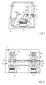
- Figure 1 shows a diagrammatic side view of a vehicle cab equipped with a bed arrangement according to the invention,
- Figure 2 shows a front view of the arrangement according to the invention,
- Figure 3 shows a diagrammatic view I of the backrest shown in Figure 1 when its cushions are removed,
- Figure 4 shows a diagrammatic view II of the arrangement according to the invention shown in Figures 2 and 3, when the upper backrest part is in the vertical position, and
- Figure 5 shows a diagrammatic view II of the arrangement according to the invention shown in Figures 2 and 3, when the upper backrest part is in the horizontal position.
- In Figures 1 and 2, the
coupé area 1 of a vehicle cab is shown diagrammatically. The vehicle cab is arranged on top of a conventional framework (not shown) which constitutes part of a vehicle chassis. The cab is provided with acab floor 2 which separates thecoupé area 1 from the vehicle chassis. Thecab floor 2, which is designed with anengine cowl 3 projecting into thecoupé area 1 and covering a drive unit (not shown) attached to the framework, is connected at its rear to avertical cab wall 4 which delimits thecoupé area 1 to the rear. - A board-shaped member, which will be referred to hereinafter as the
bed cushion 6, is arranged transversely in thecoupé area 1. Thebed cushion 6 is pivotably arranged on thecab wall 4 between a vertical stowing position and an essentially horizontal position in which it constitutes part of a bed. In the horizontal position, thebed cushion 6 passes in between thebackrests 7 of twovehicle seats 8 situated close to each other. In Figures 1 and 2, thebed cushion 6 is shown by full lines in the vertical position, whereas in Figure 2 it is shown with dot-and-dash lines in the horizontal position. - Furthermore, on the
cab wall 4 behind eachvehicle seat 8, there is arranged at least onesupport part 5 whose function will be described further below. - The two
vehicle seats 8 are identical from the standpoint of the invention. Therefore, only the one vehicle seat is described below, it being understood that the description also applies to the other vehicle seat. - The
vehicle seat 8 also comprises, in addition to thebackrest 7, aseat part 9. Theseat part 9 is connected to aseat support 10 which bears displaceably on two elongateparallel rails 11 in thecab floor 2. Between the seat support 10 and therails 11, a conventional, and therefore not shown, locking mechanism is designed to releasably lock the position of thevehicle seat 8 along therails 11. - The
backrest 7 comprises an upper and alower backrest part lower backrest part 15 is connected in an articulated manner to theseat part 9, via afirst articulation member 16 extending in the transverse direction of the vehicle, in order to make it possible to fold thebackrest 7 forwards or backwards in the longitudinal direction of the vehicle once an actuable locking member has been activated. Thefirst articulation member 16 and its locking member do not constitute part of the present invention and are therefore not described in greater detail. - The
lower backrest part 15 is connected in an articulated manner to theupper backrest part 14 via asecond articulation member 20. Thearticulation member 20, which is arranged essentially parallel to thefirst articulation member 16, is designed to permit pivoting of theupper backrest part 14 relative to thelower backrest part 15 between a first position, in which thebackrest parts integral backrest 7, and a second essentially horizontal position in which the upper backrest part constitutes part of the bed. - Figures 3 to 5 show diagrammatically the supporting parts of the
backrest parts second articulation member 20 after the cushions of thebackrest 7 have been removed. In the figures, only those details are shown which are of importance for an understanding of the invention. - The upper and
lower backrest parts legs 21 of the steel framework of the upper backrest part partially overlap with thelegs 22 of the steel framework of the lower backrest part and are, at theirlower part 23, essentially of semicircular form. Along theperiphery 24 of the semicircle,teeth 25 are arranged to co-operate withlocking members 26 in order to secure the angular position between thebackrest parts shaft 27 passing transversely through thevehicle seat 8. The twolocking members 26 are identical from the standpoint of the invention, for which reason only the onelocking member 26 is described below. - The
locking member 26 consists of ahousing 29 designed withflanges 30 through which screws (not shown) extend in order to attach thehousing 29 to theleg 22 of thelower backrest part 15. Thehousing 29 is designed with aninternal channel 31 which, at one end, is designed with agable wall 32 with acontinuous hole 33, which constitutes a support surface for an elongate actuatingmember 34 which is connected (in a manner not shown) to apin 35 arranged displaceably in thechannel 31. Thepin 35 is designed at one end withteeth 36, while its other end bears against acompression spring 37 which surrounds theelongate member 34 and bears against thegable wall 32 of the housing. - The
compression spring 37 exerts a force on thepin 35, which force tends to displace thepin 35 out of thehousing 29, in which respect theteeth 36 of thepin 35 are caused to co-operate with theteeth 25 on thesemicircular periphery 24, in order to thereby secure the position of thebackrest parts - The
teeth 36 of thepin 35 are released from co-operation with theteeth 25 of thesemicircular periphery 24 by means of manual actuation of arelease mechanism 39 which comprises the previously mentionedelongate member 34, whose one end is connected to thepin 35 and whose other end is designed with aball head 41 or the like and is accessible in the area of thejoin 42 between thelower backrest part 15 and theseat part 9. - In order to make it possible to actuate both locking
members 26 with one single control, i.e. theball head 41, the lower parts of theactuation members 34 are connected to each other via ashaft 44 passing transversely through thevehicle seat 8. - The solution according to the invention has the following function.
- The adjustment of each vehicle seat from being a seating place to part of a bed is initiated by the locking member of the
first articulation member 16 being actuated with one hand, and thebackrest 7 then being folded forwards in the longitudinal direction of the vehicle. Thereafter, with the aid of theball head 41, theelongate actuation member 34 is driven downwards in the longitudinal direction of thebackrest 7. When theactuation member 34 is driven downwards, thepin 35 movable in the axial direction is displaced in such a way that co-operation between theteeth 36 of thepin 35 and theteeth 25 of thesemicircular periphery 24 ceases. - When the locking co-operation between the
teeth upper backrest part 14 is folded backwards in the longitudinal direction of the vehicle and takes up an essentially horizontal position, in which it bears against the support parts on thecab wall 4. When theupper backrest part 14 has taken up a horizontal position, theball head 41 is released and thecompression spring 37 displaces thepin 35 towards thesemicircular periphery 24 and, thereafter, theteeth - After the
backrests 7 of the vehicle seats 8 have been converted to parts of a bed, thebed cushion 6 pivotably arranged on thecab wall 4 is pivoted from the vertical stowing position to an essentially horizontal position between the vehicle seats 8 and forms, together with theupper backrest parts 14, an integral bed. - The invention should not be regarded as being limited by the described embodiment, but can be modified within the scope of the subsequent patent claims in a number of alternative embodiments.
- With the exemplary embodiment described, it is possible to secure the backrest parts in any arbitrary angular position relative to each other. However, it is also possible, without departing from the inventive concept, to design the locking member in such a way that it only secures the angular position between the parts when these are essentially in line with each other and form an integral backrest.
- In order to obtain a bed which is essentially as long as the cab is wide, it is possible to complete the described bed arrangement with one or more board-shaped bed cushions. An example of this is shown in Figure 2. A relatively
short bed cushion 12 is pivotably arranged on the cab wall between a vertical stowing position and an essentially horizontal position. In the horizontal position, the bed cushion passes in between the one vehicle seat and the side wall of the cab and constitutes an extension of the bed. It is of course possible to arrange a corresponding bed cushion for the other vehicle seat. - In the exemplary embodiment, bed cushions are used in combination with vehicle seats in order to obtain a sufficiently long bed. It is of course possible to position sufficiently wide vehicle seats close to each other so that these themselves form a sufficiently long bed.
- In the exemplary embodiment described, two separate members are actuated in order to make it possible to swing the lower backrest part forwards in the longitudinal direction of the vehicle and the upper backrest part backwards in the longitudinal direction. It is of course possible to integrate the members with each other so that a single member is actuated in a first direction in order to swing the lower backrest part forwards, but is actuated in another direction in order to swing the lower backrest part backwards.
Claims (9)
- Bed arrangement in the coupé area of a vehicle, comprising vehicle seats (8) which can be converted into at least a part of a bed and which each comprise a seat part (9) and a backrest (7) connected to the latter, characterized in that, for each seat, the backrest (7) comprises an upper and a lower backrest part (14,15), in which respect the lower backrest part (15) is connected in an articulated manner to the seat part (9) via a first articulation member (16), and is connected in an articulated manner to the upper backrest part (14) via a second articulation member (20), in that the second articulation member (20) is designed to permit pivoting of the upper backrest part (14) relative to the lower backrest part (15) between a first position, in which the backrest parts (14,15) are essentially in line with each other and form an integral backrest (7), and a second essentially horizontal position, in which the upper backrest part (14) constitutes part of the bed, and in that the second articulation member (20) comprises at least one locking member for securing the position of the backrest parts (14,15) relative to each other in at least the first position.
- Bed arrangement according to Claim 1, characterized in that, when each vehicle seat (8) is converted into part of the bed, the lower backrest part (15) is pivoted forwards in the longitudinal direction of the vehicle by means of the first articulation member (16), and at the same time the upper backrest part (14) is pivoted backwards in the longitudinal direction of the vehicle by means of the second articulation member (20).
- Bed arrangement according to Claim 2, characterized in that the upper backrest part (14) in the folded-back position bears against at least one support part(5) arranged in the vicinity of a rear wall (4) delimiting the coupé area.
- Bed arrangement according to Claim 1, characterized in that the first and the second articulation members (16,20) are arranged essentially parallel to each other and extend in the transverse direction of the vehicle.
- Bed arrangement according to Claim 1, characterized in that the upper backrest parts (14) of the vehicle seats in the horizontal position constitute an integral bed surface together with at least one board-shaped member (6).
- Bed arrangement according to Claim 5, characterized in that the upper backrest parts (14) constitute an integral bed surface together with two board-shaped members (6), in which respect one board-shaped member (6) is arranged to pass in between two vehicle seats (8) situated close to each other, while the second board-shaped member is arranged to pass in between a vehicle seat (8) and a side wall of the coupé area.
- Bed arrangement according to Claim 5, characterized in that the board-shaped member (6) is pivotably arranged on the rear wall (4) between an essentially vertical stowing position and an essentially horizontal position in which it constitutes part of the bed.
- Bed arrangement according to Claim 1, characterized in that the locking member (32) is actuated by manual actuation of an actuation member (38) connected to the locking member, in order to release the securing of the upper backrest part (14) relative to the lower backrest part (15).
- Bed arrangement according to Claim 8, characterized in that the actuation member (38) consists of an elongate member whose one end is connected to the locking member (32) and whose other end is situated close by the join (40) between the lower backrest part (15) and the seat part (9).
Applications Claiming Priority (2)
| Application Number | Priority Date | Filing Date | Title |
|---|---|---|---|
| SE8900505A SE470058B (en) | 1989-02-15 | 1989-02-15 | Bed arrangement in a vehicle's compartment |
| SE8900505 | 1989-02-15 |
Publications (3)
| Publication Number | Publication Date |
|---|---|
| EP0388380A2 EP0388380A2 (en) | 1990-09-19 |
| EP0388380A3 EP0388380A3 (en) | 1991-12-04 |
| EP0388380B1 true EP0388380B1 (en) | 1994-05-18 |
Family
ID=20375047
Family Applications (1)
| Application Number | Title | Priority Date | Filing Date |
|---|---|---|---|
| EP90850059A Expired - Lifetime EP0388380B1 (en) | 1989-02-15 | 1990-02-08 | Bed arrangement in the rear area of a vehicle compartment |
Country Status (5)
| Country | Link |
|---|---|
| US (1) | US5029929A (en) |
| EP (1) | EP0388380B1 (en) |
| BR (1) | BR9000669A (en) |
| DE (1) | DE69008903T2 (en) |
| SE (1) | SE470058B (en) |
Families Citing this family (18)
| Publication number | Priority date | Publication date | Assignee | Title |
|---|---|---|---|---|
| FR2692122B1 (en) * | 1992-06-16 | 1995-10-13 | Lauxerrois Bernard | BED SEAT DEVICE FOR ALL VEHICLES. |
| US5911471A (en) * | 1997-03-21 | 1999-06-15 | New Holland North America, Inc. | Dual pivoting buddy seat with sliding utility tray |
| EP0842812B1 (en) | 1996-11-12 | 2004-12-08 | CNH Belgium N.V. | Dual pivoting buddy seat with sliding utility tray |
| CA2385504C (en) * | 1999-10-22 | 2008-12-09 | Mack Trucks, Inc. | Modular sleeping compartment for trucks |
| US6899379B1 (en) | 1999-10-22 | 2005-05-31 | Mack Trucks, Inc. | Modular sleeping compartment for trucks |
| SE518291C2 (en) * | 2000-08-04 | 2002-09-17 | Volvo Lastvagnar Ab | Chair and bed combination |
| US6513876B1 (en) | 2000-11-17 | 2003-02-04 | Gayle D. Agler | Multiple function boat seat |
| US6711762B2 (en) | 2002-01-30 | 2004-03-30 | Ktk Services, Inc. | Method of using a truck cab bridge bed |
| US6837531B2 (en) * | 2002-07-24 | 2005-01-04 | Daimlerchrysler Corporation | Flip seat arrangement having upper seat back pivot |
| DE10237782A1 (en) * | 2002-08-17 | 2004-02-26 | Daimlerchrysler Ag | Combined spare seat and resting area for single lorry driver traveling long distances, comprising folding seat, folding sleeping area and storage unit |
| US6935679B2 (en) * | 2003-09-03 | 2005-08-30 | Mack Trucks, Inc. | Modular cab, sleeper and roof structural assembly for a truck-tractor vehicle |
| FR2875210B1 (en) * | 2004-09-13 | 2006-11-24 | Renault V I Sa | SELF-ENGINE VEHICLE CAB |
| DE102005041761A1 (en) * | 2005-09-01 | 2006-10-26 | Daimlerchrysler Ag | Multi-purpose resting unit for drivers cabin of lorry, comprising rigid cover for sleeping area |
| US7934762B2 (en) * | 2005-12-13 | 2011-05-03 | Mack Trucks, Inc. | Vehicle with sleeping arrangement |
| DE102006014718B3 (en) * | 2006-03-30 | 2007-10-04 | Daimlerchrysler Ag | Couch device for driver`s cab of lorry, has couch arranged to backrest part, where part in tucking position covers control unit, which is arranged to rear wall of cab, and couch has seat part displaced between tucking and sleeping positions |
| US7380295B2 (en) * | 2006-07-17 | 2008-06-03 | Robert Richardson | Bridge bed between adjacent seats |
| WO2013085474A2 (en) * | 2011-11-03 | 2013-06-13 | Erk Sitki Alp | Modular airplane seat unit |
| DE102024125692A1 (en) * | 2024-09-06 | 2026-03-12 | Daimler Truck AG | Functional component for sound insulation for a commercial vehicle, commercial vehicle and process |
Family Cites Families (20)
| Publication number | Priority date | Publication date | Assignee | Title |
|---|---|---|---|---|
| US491602A (en) * | 1893-02-14 | Convertible chair | ||
| DE515873C (en) * | 1929-11-24 | 1931-01-14 | Oswald Voigt Fa | Ambulance seat for ambulance |
| FR1023491A (en) * | 1950-08-16 | 1953-03-19 | Cie Internationale Des Wagons | Improvement in the layout of sleeping car compartments with single and twin beds |
| DE939553C (en) * | 1953-03-12 | 1956-02-23 | Suedwerke Motoren Und Kraftwag | Driver's cab for trucks or the like. |
| DE1119135B (en) * | 1960-03-01 | 1961-12-07 | Stuttgarter Karosseriewerk Reu | Articulated fitting for seats with adjustable backrest, especially for motor vehicles |
| US3097881A (en) * | 1961-01-10 | 1963-07-16 | Gilbert E Aguilar | Vehicle cushion arrangement |
| DE1430921A1 (en) * | 1964-07-17 | 1968-12-12 | Daimler Benz Ag | Driver's cab for vehicles with at least one passenger couch |
| DE1580388A1 (en) * | 1966-04-29 | 1970-11-12 | Maschf Augsburg Nuernberg Ag | Berth for motor vehicle cabs |
| US3374032A (en) * | 1967-02-13 | 1968-03-19 | Hardman Tool And Engineering C | Aircraft seat |
| GB1161870A (en) * | 1967-08-08 | 1969-08-20 | Daimler Benz Ag | Improvements relating to Sleeping Arrangements in Vehicles. |
| JPS5315528Y2 (en) * | 1972-05-05 | 1978-04-24 | ||
| US4106809A (en) * | 1977-07-26 | 1978-08-15 | Karlis Minka | Convertible seat of a vehicle |
| DE2739415C2 (en) * | 1977-09-01 | 1982-07-29 | M.A.N. Maschinenfabrik Augsburg-Nürnberg AG, 8000 München | Sleeping facilities in long-haul cabs for trucks with built-in caravans |
| US4343508A (en) * | 1980-01-18 | 1982-08-10 | Lear Siegler, Inc. | Latch mechanism for vehicle seat convertible to bed |
| EP0036758A1 (en) * | 1980-03-21 | 1981-09-30 | Motor Panels (Coventry) Limited | Sleeping arrangement for drivers' cabs |
| US4620335A (en) * | 1984-12-21 | 1986-11-04 | Dodgen Industries, Inc. | Lower bed structure for a recreational vehicle |
| FR2589800B1 (en) * | 1985-11-08 | 1989-06-23 | Peugeot Cycles | TRANSFORMABLE REAR SEAT |
| DE3716817A1 (en) * | 1986-05-28 | 1987-12-03 | Volkswagen Ag | ADJUSTMENT FOR A REAR SEAT BACKREST IN A MOTOR VEHICLE |
| FR2604958B1 (en) * | 1986-10-10 | 1988-12-09 | Renault | MOTOR VEHICLE WITH THREE ROWS OF SEATS |
| DE3723311A1 (en) * | 1987-07-15 | 1989-01-26 | Keiper Recaro Gmbh Co | Free-pivoting device for the backrest of a vehicle seat |
-
1989
- 1989-02-15 SE SE8900505A patent/SE470058B/en not_active IP Right Cessation
-
1990
- 1990-02-08 EP EP90850059A patent/EP0388380B1/en not_active Expired - Lifetime
- 1990-02-08 DE DE69008903T patent/DE69008903T2/en not_active Expired - Fee Related
- 1990-02-14 US US07/480,027 patent/US5029929A/en not_active Expired - Fee Related
- 1990-02-14 BR BR909000669A patent/BR9000669A/en not_active IP Right Cessation
Also Published As
| Publication number | Publication date |
|---|---|
| US5029929A (en) | 1991-07-09 |
| DE69008903D1 (en) | 1994-06-23 |
| DE69008903T2 (en) | 1994-12-08 |
| SE470058B (en) | 1993-11-01 |
| SE8900505D0 (en) | 1989-02-15 |
| EP0388380A2 (en) | 1990-09-19 |
| EP0388380A3 (en) | 1991-12-04 |
| BR9000669A (en) | 1991-01-15 |
| SE8900505L (en) | 1990-08-16 |
Similar Documents
| Publication | Publication Date | Title |
|---|---|---|
| US5029929A (en) | Bed arrangement in the coupe area of a vehicle | |
| EP0940288B1 (en) | Seat device of a vehicle | |
| EP1483132B1 (en) | Drop down stow in floor automotive vehicle seat assembly | |
| EP0423669B1 (en) | A motor car with three front seats side by side | |
| US4269446A (en) | Displaceable seat for automotive vehicles | |
| GB2155780A (en) | A seat having a pivotable back-rest | |
| CN108725268A (en) | With the vehicle for rotating inward seat | |
| EP1586482B1 (en) | Seat device for a vehicle and vehicle provided therewith | |
| US4846520A (en) | Front seat assembly for motor vehicles, particularly motor cars | |
| US6170898B1 (en) | Pivot assembly for a vehicle seat | |
| US6773050B1 (en) | Space efficient and adaptable vehicle interior | |
| US4218091A (en) | Reclinable vehicle chair and conversion method | |
| JP3085585B2 (en) | Car body | |
| JPS6325977B2 (en) | ||
| WO2009036007A1 (en) | Vehicle seat | |
| EP1945477B1 (en) | Second row seat assembly having fold flat mechanism with forward cushion movement | |
| JPS61222831A (en) | car back seat | |
| JP3607508B2 (en) | Body | |
| EP1226998B1 (en) | Cab of an industrial vehicle, provided with a seat | |
| US5727478A (en) | Pop-up table assembly | |
| EP1593546B1 (en) | Drop down stow in floor automotive vehicle set assembly | |
| RU2042542C1 (en) | Vehicle cab | |
| GB2293316A (en) | Vehicle seat with support stay | |
| JPH0127956Y2 (en) | ||
| JPH0611229Y2 (en) | Rear seat for automobile |
Legal Events
| Date | Code | Title | Description |
|---|---|---|---|
| PUAI | Public reference made under article 153(3) epc to a published international application that has entered the european phase |
Free format text: ORIGINAL CODE: 0009012 |
|
| 17P | Request for examination filed |
Effective date: 19900222 |
|
| AK | Designated contracting states |
Kind code of ref document: A2 Designated state(s): DE ES FR GB IT NL |
|
| PUAL | Search report despatched |
Free format text: ORIGINAL CODE: 0009013 |
|
| AK | Designated contracting states |
Kind code of ref document: A3 Designated state(s): DE ES FR GB IT NL |
|
| 17Q | First examination report despatched |
Effective date: 19930503 |
|
| GRAA | (expected) grant |
Free format text: ORIGINAL CODE: 0009210 |
|
| AK | Designated contracting states |
Kind code of ref document: B1 Designated state(s): DE ES FR GB IT NL |
|
| PG25 | Lapsed in a contracting state [announced via postgrant information from national office to epo] |
Ref country code: IT Free format text: LAPSE BECAUSE OF FAILURE TO SUBMIT A TRANSLATION OF THE DESCRIPTION OR TO PAY THE FEE WITHIN THE PRE;WARNING: LAPSES OF ITALIAN PATENTS WITH EFFECTIVE DATE BEFORE 2007 MAY HAVE OCCURRED AT ANY TIME BEFORE 2007. THE CORRECT EFFECTIVE DATE MAY BE DIFFERENT FROM THE ONE RECORDED.SCRIBED TIME-LIMIT Effective date: 19940518 Ref country code: FR Effective date: 19940518 Ref country code: NL Effective date: 19940518 Ref country code: ES Free format text: THE PATENT HAS BEEN ANNULLED BY A DECISION OF A NATIONAL AUTHORITY Effective date: 19940518 |
|
| REF | Corresponds to: |
Ref document number: 69008903 Country of ref document: DE Date of ref document: 19940623 |
|
| EN | Fr: translation not filed | ||
| NLV1 | Nl: lapsed or annulled due to failure to fulfill the requirements of art. 29p and 29m of the patents act | ||
| PLBE | No opposition filed within time limit |
Free format text: ORIGINAL CODE: 0009261 |
|
| STAA | Information on the status of an ep patent application or granted ep patent |
Free format text: STATUS: NO OPPOSITION FILED WITHIN TIME LIMIT |
|
| 26N | No opposition filed | ||
| REG | Reference to a national code |
Ref country code: GB Ref legal event code: 732E |
|
| PGFP | Annual fee paid to national office [announced via postgrant information from national office to epo] |
Ref country code: GB Payment date: 19970130 Year of fee payment: 8 |
|
| PG25 | Lapsed in a contracting state [announced via postgrant information from national office to epo] |
Ref country code: GB Free format text: LAPSE BECAUSE OF NON-PAYMENT OF DUE FEES Effective date: 19980208 |
|
| GBPC | Gb: european patent ceased through non-payment of renewal fee |
Effective date: 19980208 |
|
| PGFP | Annual fee paid to national office [announced via postgrant information from national office to epo] |
Ref country code: DE Payment date: 19990212 Year of fee payment: 10 |
|
| PG25 | Lapsed in a contracting state [announced via postgrant information from national office to epo] |
Ref country code: DE Free format text: LAPSE BECAUSE OF NON-PAYMENT OF DUE FEES Effective date: 20001201 |