EP0388252B1 - Verfahren zur Abtrennung kondensierbarer Dämpfe von Feststoffteilchen in hochkomprimierten Gasen - Google Patents
Verfahren zur Abtrennung kondensierbarer Dämpfe von Feststoffteilchen in hochkomprimierten Gasen Download PDFInfo
- Publication number
- EP0388252B1 EP0388252B1 EP90400595A EP90400595A EP0388252B1 EP 0388252 B1 EP0388252 B1 EP 0388252B1 EP 90400595 A EP90400595 A EP 90400595A EP 90400595 A EP90400595 A EP 90400595A EP 0388252 B1 EP0388252 B1 EP 0388252B1
- Authority
- EP
- European Patent Office
- Prior art keywords
- particles
- flow apparatus
- compressed gas
- condensible
- vapors
- Prior art date
- Legal status (The legal status is an assumption and is not a legal conclusion. Google has not performed a legal analysis and makes no representation as to the accuracy of the status listed.)
- Expired - Lifetime
Links
- 239000002245 particle Substances 0.000 title claims abstract description 87
- 238000000034 method Methods 0.000 title claims abstract description 31
- 239000007789 gas Substances 0.000 title abstract description 59
- 238000001228 spectrum Methods 0.000 claims abstract description 9
- 229930195733 hydrocarbon Natural products 0.000 claims description 12
- 150000002430 hydrocarbons Chemical class 0.000 claims description 12
- 238000004458 analytical method Methods 0.000 claims description 7
- 239000012535 impurity Substances 0.000 claims description 7
- 239000004215 Carbon black (E152) Substances 0.000 claims description 3
- 230000000717 retained effect Effects 0.000 claims 1
- 239000007858 starting material Substances 0.000 claims 1
- 238000009792 diffusion process Methods 0.000 abstract description 10
- 238000005070 sampling Methods 0.000 abstract description 6
- 238000009833 condensation Methods 0.000 description 6
- 230000005494 condensation Effects 0.000 description 6
- 239000012159 carrier gas Substances 0.000 description 5
- 230000007423 decrease Effects 0.000 description 4
- 238000004519 manufacturing process Methods 0.000 description 4
- 238000000746 purification Methods 0.000 description 4
- IJGRMHOSHXDMSA-UHFFFAOYSA-N Atomic nitrogen Chemical compound N#N IJGRMHOSHXDMSA-UHFFFAOYSA-N 0.000 description 3
- CURLTUGMZLYLDI-UHFFFAOYSA-N Carbon dioxide Chemical compound O=C=O CURLTUGMZLYLDI-UHFFFAOYSA-N 0.000 description 3
- 238000013461 design Methods 0.000 description 3
- 238000001514 detection method Methods 0.000 description 3
- XKRFYHLGVUSROY-UHFFFAOYSA-N Argon Chemical compound [Ar] XKRFYHLGVUSROY-UHFFFAOYSA-N 0.000 description 2
- OKTJSMMVPCPJKN-UHFFFAOYSA-N Carbon Chemical compound [C] OKTJSMMVPCPJKN-UHFFFAOYSA-N 0.000 description 2
- ATUOYWHBWRKTHZ-UHFFFAOYSA-N Propane Chemical compound CCC ATUOYWHBWRKTHZ-UHFFFAOYSA-N 0.000 description 2
- 239000002253 acid Substances 0.000 description 2
- 239000000443 aerosol Substances 0.000 description 2
- 238000009835 boiling Methods 0.000 description 2
- 239000003638 chemical reducing agent Substances 0.000 description 2
- 150000001875 compounds Chemical class 0.000 description 2
- 238000001816 cooling Methods 0.000 description 2
- 230000003247 decreasing effect Effects 0.000 description 2
- 230000007547 defect Effects 0.000 description 2
- 238000004817 gas chromatography Methods 0.000 description 2
- 239000007788 liquid Substances 0.000 description 2
- VNWKTOKETHGBQD-UHFFFAOYSA-N methane Chemical compound C VNWKTOKETHGBQD-UHFFFAOYSA-N 0.000 description 2
- 238000011144 upstream manufacturing Methods 0.000 description 2
- UGFAIRIUMAVXCW-UHFFFAOYSA-N Carbon monoxide Chemical compound [O+]#[C-] UGFAIRIUMAVXCW-UHFFFAOYSA-N 0.000 description 1
- OTMSDBZUPAUEDD-UHFFFAOYSA-N Ethane Chemical compound CC OTMSDBZUPAUEDD-UHFFFAOYSA-N 0.000 description 1
- 238000004566 IR spectroscopy Methods 0.000 description 1
- 229910002651 NO3 Inorganic materials 0.000 description 1
- NHNBFGGVMKEFGY-UHFFFAOYSA-N Nitrate Chemical compound [O-][N+]([O-])=O NHNBFGGVMKEFGY-UHFFFAOYSA-N 0.000 description 1
- GRYLNZFGIOXLOG-UHFFFAOYSA-N Nitric acid Chemical compound O[N+]([O-])=O GRYLNZFGIOXLOG-UHFFFAOYSA-N 0.000 description 1
- 238000004847 absorption spectroscopy Methods 0.000 description 1
- 238000003915 air pollution Methods 0.000 description 1
- 238000013459 approach Methods 0.000 description 1
- 229910052786 argon Inorganic materials 0.000 description 1
- 239000001569 carbon dioxide Substances 0.000 description 1
- 229910002092 carbon dioxide Inorganic materials 0.000 description 1
- 235000011089 carbon dioxide Nutrition 0.000 description 1
- 229910002091 carbon monoxide Inorganic materials 0.000 description 1
- 238000004587 chromatography analysis Methods 0.000 description 1
- 239000011248 coating agent Substances 0.000 description 1
- 238000000576 coating method Methods 0.000 description 1
- 238000007796 conventional method Methods 0.000 description 1
- 238000005516 engineering process Methods 0.000 description 1
- 230000007613 environmental effect Effects 0.000 description 1
- 238000005429 filling process Methods 0.000 description 1
- 238000001914 filtration Methods 0.000 description 1
- 239000010419 fine particle Substances 0.000 description 1
- 239000001307 helium Substances 0.000 description 1
- 229910052734 helium Inorganic materials 0.000 description 1
- SWQJXJOGLNCZEY-UHFFFAOYSA-N helium atom Chemical compound [He] SWQJXJOGLNCZEY-UHFFFAOYSA-N 0.000 description 1
- 239000001257 hydrogen Substances 0.000 description 1
- 229910052739 hydrogen Inorganic materials 0.000 description 1
- 125000004435 hydrogen atom Chemical class [H]* 0.000 description 1
- 230000003993 interaction Effects 0.000 description 1
- 230000000873 masking effect Effects 0.000 description 1
- 238000004949 mass spectrometry Methods 0.000 description 1
- 239000002808 molecular sieve Substances 0.000 description 1
- 229910017604 nitric acid Inorganic materials 0.000 description 1
- 229910052757 nitrogen Inorganic materials 0.000 description 1
- 230000003287 optical effect Effects 0.000 description 1
- 239000008188 pellet Substances 0.000 description 1
- 239000001294 propane Substances 0.000 description 1
- 238000011946 reduction process Methods 0.000 description 1
- 238000011160 research Methods 0.000 description 1
- URGAHOPLAPQHLN-UHFFFAOYSA-N sodium aluminosilicate Chemical compound [Na+].[Al+3].[O-][Si]([O-])=O.[O-][Si]([O-])=O URGAHOPLAPQHLN-UHFFFAOYSA-N 0.000 description 1
- 238000001179 sorption measurement Methods 0.000 description 1
- 239000000126 substance Substances 0.000 description 1
- 238000012360 testing method Methods 0.000 description 1
Images

Classifications
-
- B—PERFORMING OPERATIONS; TRANSPORTING
- B01—PHYSICAL OR CHEMICAL PROCESSES OR APPARATUS IN GENERAL
- B01D—SEPARATION
- B01D53/00—Separation of gases or vapours; Recovering vapours of volatile solvents from gases; Chemical or biological purification of waste gases, e.g. engine exhaust gases, smoke, fumes, flue gases, aerosols
-
- B—PERFORMING OPERATIONS; TRANSPORTING
- B01—PHYSICAL OR CHEMICAL PROCESSES OR APPARATUS IN GENERAL
- B01D—SEPARATION
- B01D5/00—Condensation of vapours; Recovering volatile solvents by condensation
- B01D5/0027—Condensation of vapours; Recovering volatile solvents by condensation by direct contact between vapours or gases and the cooling medium
-
- B—PERFORMING OPERATIONS; TRANSPORTING
- B01—PHYSICAL OR CHEMICAL PROCESSES OR APPARATUS IN GENERAL
- B01D—SEPARATION
- B01D8/00—Cold traps; Cold baffles
Definitions
- Trace quantities of condensible vapors such as hydrocarbons or fluorinated hydrocarbons in gases are commonly detected and quantified by a variety of means such as chromatography in the gas phase, infrared (IR) absorption spectroscopy, mass spectrometry, total hydrocarbon detectors, etc.
- IR infrared
- Pressure reduction by critical orifice is commonly used in pressure regulators.
- a pressure reducer consisting of a clean orifice, a chamber into which the gas can expand, and a means to sample part of the expanding jet, can achieve "zero" particle shedding.
- Such a unit can be purchased from Liquid Air Corporation.
- Utilization of the differences in diffusion coefficients to remove unwanted nitric acid vapor from a gas stream to obtain true particulate nitrate is a common practice among air pollution researchers, where it is called "acid denuder".
- a basic coating is usually applied to the collection surfaces to retain the acid vapors, which may shed significant particles to upset the purpose of sampling particles from high-purity gases.
- the system is at ambient pressure. No temperature control is provided.
- EP-A-0312457 and EP-A-0312458 It is also known from EP-A-0312457 and EP-A-0312458 to generate droplets of condensible vapors in a carrier gas through a critical orifice and to discharge a carrier gas containing condensible vapors through a plurality of orifices without causing the condensation of the condensible vapors.
- the invention furthermore provides processes as defined in respectively claim 4 and claim 5.
- a starting compressed gas containing condensible vapors and particles is passed through a flow system.
- the flow system used comprises simple geometries and polished, clean surfaces.
- the flow rate of the compressed gas through the flow system and the flow system geometry are selected such that particles having a diameter greater than 0.01 micrometers have a collision efficiency of less than 5% with the flow system surfaces and condensible vapor molecules have a collision efficiency of at least 98% with the flow system surfaces.
- the temperature of the flow system surfaces is then controlled to retain collided vapor molecules on the surfaces. This process produces a product compressed gas which is free of condensable vapors and contains the spectra and concentration of particles of the starting compressed gas.
- the invention provides a process for removing trace amount of condensible vapor impurities from highly compressed gases without disturbing the original particle size spectra and concentrations in the compressed gas. These condensible vapors can convert into particles under conditions of large temperature drop or pressure drop and totally distort the original particle information.
- compressed gases are defined as comprising, among others, a carrier gas and condensible vapors.
- the compound gases may have pressures ranging from 6,9x10⁵ Pa (100 psia) to 20,7x10⁶ Pa (3000 psia).
- the carrier gas may be, e.g. nitrogen (N2), argon, helium, carbon dioxide, carbon monoxide, hydrogen, methane, ethane, propane, etc.
- Condensible vapors are defined for the present purposes as species which will condense to form droplets upon sufficient cooling of the carrier gas or upon contacting a sufficiently cool surface ( vide infra ), e.g. C5 ⁇ 16 hydrocarbons or C5 ⁇ 16 fluorinated hydrocarbons, etc., and higher hydrocarbons or fluorinated hydrocarbons which can include up to C30 hydrocarbons/fluorinated hydrocarbons under some circumstances, such as when these vapors are present in a very low concentration. These condensible vapors are however present in their gaseous state before cooling and not as droplets.
- the method of the invention thus distinguishes itself from other detection methods for preexisting particles and specifically from methods for the detection of preexisting oil droplets in gases which require the preexistence of such droplets.
- An example of such methods is given in U.S.-A-4794086
- the present invention provides for the removal of either global amounts of condensible vapors or individual components within a "family" of such species (for example hydrocarbons).
- Another important application of the present invention is that this method can be used for the purpose of purification of gases, especially during the cylinder filling process, to obtain ultra-clean gases.
- the present method is superior to conventional method in "zero" particle generation and low pressure drop.
- the invention removes condensible vapors in a flow system of simple geometries and of polished, clean surfaces, such as art electro-polished round tube, an annular tube, or a rectangular slit.
- simple geometries such as art electro-polished round tube, an annular tube, or a rectangular slit.
- smooth geometries is used to indicate that these flow systems do not have sharp turns and/or dead spaces to trap particles.
- the conventional vapor removing process (usually referred to as purification) utilizes complex flow systems with rough surfaces and porous pellets which can generate or trap substantial amount of particles. This conventional process is therefore not compatible with particle sampling and analysis.
- the particles contained in the compound gases treated in this invention have diameters of at least 0.01 ⁇ m.
- the invention selectively removes condensible vapor molecules without affecting the particles in the gas stream.
- the diffusion coefficients for gas molecules are orders of magnitude larger than those of particles.
- the diffusion coefficient for air molecules is 0.19 cm2.s ⁇ 1 versus 0.00052 cm2.s ⁇ 1 for particles of 0.01 ⁇ m diameter. (Note: 0.01 ⁇ m is currently the practical lower limit of detection by commonly used particle counters. The diffusion coefficient decreases further with increasing particle diameter.)
- the collision frequency with the tube walls is much higher for vapor molecules than for particles.
- CE collision efficiency
- CE 1 - 0.819 exp (-11.5K) for K > 0.007
- K DL/Q for round tube
- K DLW/QH for rectangular slit
- D is the diffusion coefficient
- L the tube length
- Q the flow rate
- W the width of the slit
- H the height of the slit.
- Tables 1 to 3 list the collision efficiency in a round tube for various tube lengths, flow rates, and diffusion coefficients. The range of diffusion coefficients covers most commonly encountered vapor species. The last row of each table indicates the diffusion loss of 0.01 ⁇ m particles. The loss decreases with increasing particle size.
- the present process retains the collided vapor molecules on the tube walls by controlling the wall temperature.
- the molecules may stick or rebound depending upon the physical and chemical interactions occurring between the vapor and the collection surface.
- Conventional purification process rely on the adsorption properties of the collection surface to retain vapor molecules.
- the sticking probability of the colliding molecules is increased by decreasing the surface temperature.
- the temperature control can be obtained by a mechanical refrigerator or a reservoir of dry ice or liquid nitrogen.
- the suitable temperature ranges lie between the boiling point of the gas to be sampled and the lowest boiling point of the condensible vapors to be removed.
- at least a portion of the surface sufficient to trap the condensible vapors must be cooled.
- the invention further provides a process for identifying the species of vapor impurities in cylinder gases. After trapping an adequate amount of vapor impurities, heated, clean gases can be directed through the tube to desorb the trapped vapors. Fourrier transform infrared spectroscopy (FTIR), gas-chromatography (GC), or other instruments can be used on-line to identify the species of the trapped vapors.
- FTIR Fourrier transform infrared spectroscopy
- GC gas-chromatography
- Figure 2 shows the schematic design for the application of sampling particles from cylinder gases.
- the tube length and the temperature control method employed here only serve as an example.
- a 0,635 cm (1/4 inch) SSEP tubing of 1,22m (4 feet) long submerged in a dry ice-freon reservoir served as the vapor removing device (cold trap).
- the temperature of the cold trap was -78°C.
- the required tube length can be found in Table 1 to 3 for different applications. With this design, the background particle levels, generated from reentrainment and condensation, were controlled well.
- the temperature control can be facilitated by a mechanical freezer, a jet-expansion device, or a reservoir filled with different liquefied gases.
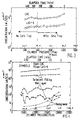
- the detected background particle concentration with an absolute filter in-line but by-passing the cold trap is given in Figure 1, which illustrates background particle levels, generated by condensation, as a function of cylinder (gas) pressure.
- Figure 1 illustrates that particle concentration increases with cylinder Pressure.
- the CNC counts are two orders of magnitude higher than the LAS-X counts.
- the detected background particle concentration with the cold trap is given in Table 4.
- the background level can be further reduced by employing a lower flow rate, a longer tube in the cold trap or a lower reservoir temperature.
- Figure 3 shows that the use of a cold trap does not cause extra particle loss.
- Figure 3 provides particle concentration data for a turbulently filled cylinder. The concentration of the particles remains the same with and without the cold trap at pressures less than 41,4x10⁵ Pa (600 psi), where no condensation occurs.
- Figure 4 shows examples of measuring true particle concentration in turbulent-filled and aged cylinders by employing the present method.
- Figure 4 provides particle concentrations for high pressure gases in cylinders with different histories.
- the concentration of particles can be different by two orders of magnitude depending on the history of the high pressure gas in the cylinder.
- concentration of particles is relatively low.
Landscapes
- Chemical & Material Sciences (AREA)
- Chemical Kinetics & Catalysis (AREA)
- Engineering & Computer Science (AREA)
- Analytical Chemistry (AREA)
- General Chemical & Material Sciences (AREA)
- Oil, Petroleum & Natural Gas (AREA)
- Sampling And Sample Adjustment (AREA)
- Vaporization, Distillation, Condensation, Sublimation, And Cold Traps (AREA)
- Drying Of Gases (AREA)
- Gas Separation By Absorption (AREA)
- Separation Of Gases By Adsorption (AREA)
Claims (5)
- Verfahren zum Entfernen kondensierbarer Dämpfe aus einem komprimierten Gas, das kondensierbare Dämpfe und Partikel enthält, ohne die Spektren oder die Konzentration dieser Partikel in dem komprimierten Gas zu beeinträchtigen, wobei das Verfahren umfaßt:(i) Leiten eines kondensierbare Dämpfe und Partikel enthaltenden komprimierten Startgases durch eine Durchlaufvorrichtung ohne scharfe Windungen und/oder Toträume, in denen sich Partikel absetzen, bevorzugt ein elektropoliertes rundes Rohr, ein ringförmiges Rohr oder einen rechteckigen Schlitz, wobei die Durchlaufvorrichtung polierte saubere Oberflächen umfaßt;(ii) Auswählen (iia) eines Durchflusses des komprimierten Gases durch die Durchlaufvorrichtung und (iib) einer Länge und Geometrie der Durchlaufvorrichtung derart, daß Partikel mit einem Durchmesser größer als 0,01µm einen Kollisionswirkungsgrad von weniger als 5% mit den Oberflächen der Durchlaufvorrichtung und kondensierte Dampfmoleküle einen Kollisionswirkungsgrad von mindestens 98% mit den Oberflächen der Durchlaufvorrichtung haben;(iii) Steuern der Temperatur von zumindest einem Bereich der Oberflächen der Durchlaufvorrichtung zum Zurückhalten kollidierter Dampfmoleküle auf diesem Bereich der Oberflächen; und(iv) Gewinnen eines komprimierten Produktgases, das frei von kondensierten Dämpfen ist und die Spektren und die Konzentration der Teilchen des komprimierten Startgases hat.
- Verfahren nach Anspruch 1, wobei die kondensierbaren Dämpfe Kohlenwasserstoff oder fluorierten Kohlenwasserstoff umfassen.
- Verfahren nach Anspruch 1 oder 2, umfassend das Befüllen eines Zylinders mit dem komprimierten Produktgas.
- Verfahren zum Identifizieren der Art kondensierbarer Dampfverunreinigungen in einem komprimierten Gas, umfassend:(i) Leiten eines kondensierbare Dämpfe enthaltenden komprimierten Startgases durch eine Durchlaufvorrichtung mit einer Länge und Geometrie derart, daß Partikel mit einem größeren Durchmesser als 0,01 µm einen Kollisionswirkungsgrad von weniger als 5 % mit den Oberflächen der Durchlaufvorrichtung und kondensierbare Dampfmoleküle einen Kollisionswirkungsgrad von zumindest 98% mit den Oberflächen der Durchlaufvorrichtung haben, wobei die Durchlaufvorrichtung eine einfache Geometrie ohne scharfe Windungen und/oder Toträume, bevorzugt einem elektropolierten runden Rohr, einem ringförmigen Rohr oder einem rechteckigen Schlitz hat und polierte, saubere Oberflächen umfaßt;(ii) Auswählen (iia) eines Durchflusses des komprimierten Gases durch die Durchlaufvorrichtung und (iib) einer Länge und Geometrie der Durchlaufvorrichtung derart, daß Partikel mit einem Durchmesser größer als 0,01µm in diesem Gas einen Kollisionswirkungsgrad von weniger als 5% mit den Oberflächen der Durchlaufvorrichtung und kondensierte Dampfmoleküle einen Kollisionswirkungsgrad von mindestens 98% mit den Oberflächen der Durchlaufvorrichtung haben;(iii) Steuern der Temperatur von zumindest einem Bereich der Oberflächen der Durchlaufvorrichtung zum Zurückhalten kollidierter Dampfmoleküle auf diesem Bereich der Oberflächen;(iv) Ersetzen des die Durchlaufvorrichtung durchsetzenden komprimierten Startgases durch ein sauberes Gas und Desorbieren der zurückgehaltenen Dampfmoleküle;(v) Identifizieren der Dampfmoleküle.
- Verfahren zur Analyse von in einem komprimierten Gas vorhandenen Partikeln, umfassend:(i) Leiten eines kondensierbare Dämpfe und Partikel enthaltenden komprimierten Startgases durch eine Durchlaufvorrichtung mit einer Länge und Geometrie derart, daß Partikel mit einem größeren Durchmesser als 0,01 µm einen Kollisionswirkungsgrad von weniger als 5 % mit den Oberflächen der Durchlaufvorrichtung und kondensierbare Dampfmoleküle einen Kollisionswirkungsgrad von zumindest 98% mit den Oberflächen der Durchlaufvorrichtung haben, wobei die Durchlaufvorrichtung eine einfache Geometrie ohne scharfe Windungen und/oder Toträume, bevorzugt einem elektropolierten runden Rohr, einem ringförmigen Rohr oder einem rechteckigen Schlitz hat und polierte, saubere Oberflächen umfaßt;(ii) Auswählen (iia) eines Durchflusses des komprimierten Gases durch die Durchlaufvorrichtung und (iib) einer Länge und Geometrie der Durchlaufvorrichtung derart, daß Partikel mit einem Durchmesser größer als 0,01µm einen Kollisionswirkungsgrad von weniger als 5% mit den Oberflächen der Durchlaufvorrichtung und kondensierte Dampfmoleküle einen Kollisionswirkungsgrad von mindestens 98% mit den Oberflächen der Durchlaufvorrichtung haben;(iii) Steuern der Temperatur von zumindest einem Bereich der Oberflächen der Durchlaufvorrichtung zum Festhalten kollidierter Dampfmoleküle auf diesem Bereich der Oberflächen;(iv) Gewinnen eines komprimierten Produktgases, das frei von kondensierten Dämpfen ist und die Spektren und die Konzentration der Teilchen des komprimierten Startgases hat;(v) Analysieren der im komprimierten Produktgas vorhandenen Partikel.
Applications Claiming Priority (2)
| Application Number | Priority Date | Filing Date | Title |
|---|---|---|---|
| US318828 | 1981-11-06 | ||
| US07/318,828 US4964278A (en) | 1989-03-06 | 1989-03-06 | Method of separating condensible vapors from particles in highly compressed gases |
Publications (3)
| Publication Number | Publication Date |
|---|---|
| EP0388252A2 EP0388252A2 (de) | 1990-09-19 |
| EP0388252A3 EP0388252A3 (de) | 1991-01-16 |
| EP0388252B1 true EP0388252B1 (de) | 1994-12-14 |
Family
ID=23239740
Family Applications (1)
| Application Number | Title | Priority Date | Filing Date |
|---|---|---|---|
| EP90400595A Expired - Lifetime EP0388252B1 (de) | 1989-03-06 | 1990-03-05 | Verfahren zur Abtrennung kondensierbarer Dämpfe von Feststoffteilchen in hochkomprimierten Gasen |
Country Status (7)
| Country | Link |
|---|---|
| US (1) | US4964278A (de) |
| EP (1) | EP0388252B1 (de) |
| JP (1) | JP3056501B2 (de) |
| KR (1) | KR900014022A (de) |
| AT (1) | ATE115429T1 (de) |
| CA (1) | CA2011474A1 (de) |
| DE (1) | DE69014946T2 (de) |
Families Citing this family (14)
| Publication number | Priority date | Publication date | Assignee | Title |
|---|---|---|---|---|
| US5205987A (en) * | 1991-02-28 | 1993-04-27 | Suprex Corporation | Off-line supercritical fluid extraction collection system |
| US5209102A (en) * | 1992-01-31 | 1993-05-11 | American Air Liquide | Method of introducing and controlling compressed gases for impurity analysis |
| US5349833A (en) * | 1993-02-22 | 1994-09-27 | Xontech, Inc. | Cryotrap for air pollution analyzer |
| US5426944A (en) * | 1993-08-31 | 1995-06-27 | American Air Liquide, Inc. | Chemical purification for semiconductor processing by partial condensation |
| US5665902A (en) * | 1994-05-10 | 1997-09-09 | American Air Liquide, Inc. | Method to analyze particle contaminants in compressed gases |
| US5814741A (en) * | 1996-03-01 | 1998-09-29 | American Air Liquide Inc. | Metal sampling method and system for non-hydrolyzable gases |
| US5941081A (en) * | 1997-10-27 | 1999-08-24 | Air Liquide America Corp. | Solid phase latent heat vapor extraction and recovery system for liquified gases |
| EP1688731A1 (de) * | 2005-02-03 | 2006-08-09 | Air Products and Chemicals, Inc. | Vorrichtung und Verfahren zur Messung und/oder Analyse von Teilchen in einem Gasstrom |
| EP1830173A1 (de) * | 2005-02-03 | 2007-09-05 | Air Products and Chemicals, Inc. | System und Verfahren mit diesem zur Messung und/oder Analyse von Partikeln in einem Gasstrom |
| US7867779B2 (en) * | 2005-02-03 | 2011-01-11 | Air Products And Chemicals, Inc. | System and method comprising same for measurement and/or analysis of particles in gas stream |
| US7592178B2 (en) * | 2005-02-23 | 2009-09-22 | Hunter Menufacturing Co. | Filter integrity tester |
| US7851750B2 (en) * | 2008-04-09 | 2010-12-14 | The United States Of America As Represented By The United States Department Of Energy | Mass independent kinetic energy reducing inlet system for vacuum environment |
| FI128773B (fi) * | 2014-12-30 | 2020-11-30 | Sisaeilmatutkimuspalvelut Elisa Aattela | Menetelmä sisäilman tutkimiseksi ja näytteenottojärjestely |
| CN110095575A (zh) * | 2019-05-08 | 2019-08-06 | 中国科学技术大学 | 混合气体中单一气体的富集纯化设备 |
Family Cites Families (9)
| Publication number | Priority date | Publication date | Assignee | Title |
|---|---|---|---|---|
| FR1203026A (fr) * | 1958-05-09 | 1960-01-14 | Air Liquide | Perfectionnements aux procédés pour l'analyse de mélanges gazeux |
| US3338034A (en) * | 1963-11-12 | 1967-08-29 | Union Carbide Corp | Adsorbent-coated thermal panels |
| FR1389059A (fr) * | 1964-01-29 | 1965-02-12 | Hochvakuum Dresden Veb | Procédé et dispositif pour l'analyse de très petites quantités de gaz à des pressions très basses |
| US4023398A (en) * | 1975-03-03 | 1977-05-17 | John Barry French | Apparatus for analyzing trace components |
| US4506513A (en) * | 1983-06-17 | 1985-03-26 | Max John K | Cold trap |
| US4530250A (en) * | 1984-04-12 | 1985-07-23 | The United States Of America As Represented By The United States Department Of Energy | Method for sampling sub-micron particles |
| DE3422417A1 (de) * | 1984-06-16 | 1985-12-19 | Kernforschungsanlage Jülich GmbH, 5170 Jülich | Verfahren und vorrichtung zur abtrennung einer gaskomponente aus einem gasgemisch durch ausfrieren |
| DE3729374C1 (de) * | 1987-09-03 | 1988-12-01 | Kernforschungsanlage Juelich | Vorrichtung zur kryogenen Anreicherung von in Gasen enthaltenen Spurenstoffen und Verwendung der Vorrichtung in einer Einrichtung |
| US5027642A (en) * | 1987-10-13 | 1991-07-02 | American Air Liquide | Method of detecting and or removing trace amounts of condensible vapors from compressed gas |
-
1989
- 1989-03-06 US US07/318,828 patent/US4964278A/en not_active Expired - Fee Related
-
1990
- 1990-03-05 CA CA002011474A patent/CA2011474A1/en not_active Abandoned
- 1990-03-05 EP EP90400595A patent/EP0388252B1/de not_active Expired - Lifetime
- 1990-03-05 JP JP2053479A patent/JP3056501B2/ja not_active Expired - Lifetime
- 1990-03-05 DE DE69014946T patent/DE69014946T2/de not_active Expired - Fee Related
- 1990-03-05 AT AT90400595T patent/ATE115429T1/de not_active IP Right Cessation
- 1990-03-06 KR KR1019900002910A patent/KR900014022A/ko not_active Ceased
Also Published As
| Publication number | Publication date |
|---|---|
| EP0388252A3 (de) | 1991-01-16 |
| KR900014022A (ko) | 1990-10-22 |
| JP3056501B2 (ja) | 2000-06-26 |
| DE69014946T2 (de) | 1995-05-04 |
| US4964278A (en) | 1990-10-23 |
| EP0388252A2 (de) | 1990-09-19 |
| ATE115429T1 (de) | 1994-12-15 |
| DE69014946D1 (de) | 1995-01-26 |
| JPH02298302A (ja) | 1990-12-10 |
| CA2011474A1 (en) | 1990-09-06 |
Similar Documents
| Publication | Publication Date | Title |
|---|---|---|
| US4964278A (en) | Method of separating condensible vapors from particles in highly compressed gases | |
| EP0312457B1 (de) | Verfahren zur Bestimmung von Spuren von kondensierbaren Verunreinigungen in einem komprimierten Gas | |
| Bloom et al. | Determination of volatile mercury species at the picogram level by low-temperature gas chromatography with cold-vapour atomic fluorescence detection | |
| EP0203340B1 (de) | Verfahren zur Entfernung leichter flüchtiger Verunreinigungen aus Gasen | |
| Thiemens et al. | Oxygen isotope fractionation in stratospheric CO2 | |
| US7867779B2 (en) | System and method comprising same for measurement and/or analysis of particles in gas stream | |
| US4961966A (en) | Fluorocarbon coating method | |
| KR920007160B1 (ko) | 응축핵 계수에 의한 입자의 사이징 방법 | |
| EP1688731A1 (de) | Vorrichtung und Verfahren zur Messung und/oder Analyse von Teilchen in einem Gasstrom | |
| Subramanyam et al. | Gas-to-particle partitioning of polycyclic aromatic hydrocarbons in an urban atmosphere | |
| Hoering et al. | The isotopic composition of the nitrogen in natural gases and associated crude oils | |
| CN1094163A (zh) | 脉石中的重烃的鉴定方法及其装置 | |
| Krieger et al. | Measurement of polychlorinated biphenyls and polycyclic aromatic hydrocarbons in air with a diffusion denuder | |
| CN101839878A (zh) | 高纯气(或电子气)中痕量气态杂质分析方法和装置 | |
| D'Ottavio et al. | Perfluorocarbon measurement using an automated dual-trap analyzer | |
| US5814741A (en) | Metal sampling method and system for non-hydrolyzable gases | |
| Golovoy et al. | Adsorption of automotive paint solvents on activated carbon: I. Equilibrium adsorption of single vapors | |
| US20070261559A1 (en) | Analysis of a reactive gas such as silane for particle generating impurities | |
| Clemons et al. | Concentration and ultrasensitive chromatographic determination of sulfur hexafluoride for application to meteorological tracing | |
| JP7625082B2 (ja) | 微量及び超微量含油量の測定方法及び装置 | |
| JPH023799A (ja) | 高圧圧縮ガス減圧方法 | |
| Hanrahan et al. | Adsorption-desorption gas chromatographic-infrared determination of trace disulfur decafluoride in sulfur hexafluoride | |
| EP1830173A1 (de) | System und Verfahren mit diesem zur Messung und/oder Analyse von Partikeln in einem Gasstrom | |
| Stehr et al. | Collection and analysis of atmospheric ozone samples | |
| US3724169A (en) | Delta t bar spectrometer |
Legal Events
| Date | Code | Title | Description |
|---|---|---|---|
| PUAI | Public reference made under article 153(3) epc to a published international application that has entered the european phase |
Free format text: ORIGINAL CODE: 0009012 |
|
| 17P | Request for examination filed |
Effective date: 19900309 |
|
| AK | Designated contracting states |
Kind code of ref document: A2 Designated state(s): AT BE CH DE DK ES FR GB IT LI LU NL SE |
|
| PUAL | Search report despatched |
Free format text: ORIGINAL CODE: 0009013 |
|
| AK | Designated contracting states |
Kind code of ref document: A3 Designated state(s): AT BE CH DE DK ES FR GB IT LI LU NL SE |
|
| 17Q | First examination report despatched |
Effective date: 19930212 |
|
| GRAA | (expected) grant |
Free format text: ORIGINAL CODE: 0009210 |
|
| AK | Designated contracting states |
Kind code of ref document: B1 Designated state(s): AT BE CH DE DK ES FR GB IT LI LU NL SE |
|
| PG25 | Lapsed in a contracting state [announced via postgrant information from national office to epo] |
Ref country code: CH Effective date: 19941214 Ref country code: ES Free format text: THE PATENT HAS BEEN ANNULLED BY A DECISION OF A NATIONAL AUTHORITY Effective date: 19941214 Ref country code: BE Effective date: 19941214 Ref country code: DK Effective date: 19941214 Ref country code: AT Effective date: 19941214 Ref country code: LI Effective date: 19941214 Ref country code: NL Effective date: 19941214 Ref country code: IT Free format text: LAPSE BECAUSE OF FAILURE TO SUBMIT A TRANSLATION OF THE DESCRIPTION OR TO PAY THE FEE WITHIN THE PRE;WARNING: LAPSES OF ITALIAN PATENTS WITH EFFECTIVE DATE BEFORE 2007 MAY HAVE OCCURRED AT ANY TIME BEFORE 2007. THE CORRECT EFFECTIVE DATE MAY BE DIFFERENT FROM THE ONE RECORDED.SCRIBED TIME-LIMIT Effective date: 19941214 |
|
| REF | Corresponds to: |
Ref document number: 115429 Country of ref document: AT Date of ref document: 19941215 Kind code of ref document: T |
|
| REF | Corresponds to: |
Ref document number: 69014946 Country of ref document: DE Date of ref document: 19950126 |
|
| ET | Fr: translation filed | ||
| PG25 | Lapsed in a contracting state [announced via postgrant information from national office to epo] |
Ref country code: SE Effective date: 19950314 |
|
| PG25 | Lapsed in a contracting state [announced via postgrant information from national office to epo] |
Ref country code: LU Free format text: LAPSE BECAUSE OF NON-PAYMENT OF DUE FEES Effective date: 19950331 |
|
| REG | Reference to a national code |
Ref country code: CH Ref legal event code: PL |
|
| NLV1 | Nl: lapsed or annulled due to failure to fulfill the requirements of art. 29p and 29m of the patents act | ||
| PLBE | No opposition filed within time limit |
Free format text: ORIGINAL CODE: 0009261 |
|
| STAA | Information on the status of an ep patent application or granted ep patent |
Free format text: STATUS: NO OPPOSITION FILED WITHIN TIME LIMIT |
|
| 26N | No opposition filed | ||
| PGFP | Annual fee paid to national office [announced via postgrant information from national office to epo] |
Ref country code: FR Payment date: 19970210 Year of fee payment: 8 |
|
| PGFP | Annual fee paid to national office [announced via postgrant information from national office to epo] |
Ref country code: GB Payment date: 19970220 Year of fee payment: 8 |
|
| PGFP | Annual fee paid to national office [announced via postgrant information from national office to epo] |
Ref country code: DE Payment date: 19970224 Year of fee payment: 8 |
|
| PG25 | Lapsed in a contracting state [announced via postgrant information from national office to epo] |
Ref country code: GB Free format text: LAPSE BECAUSE OF NON-PAYMENT OF DUE FEES Effective date: 19980305 |
|
| PG25 | Lapsed in a contracting state [announced via postgrant information from national office to epo] |
Ref country code: FR Free format text: THE PATENT HAS BEEN ANNULLED BY A DECISION OF A NATIONAL AUTHORITY Effective date: 19980331 |
|
| GBPC | Gb: european patent ceased through non-payment of renewal fee |
Effective date: 19980305 |
|
| PG25 | Lapsed in a contracting state [announced via postgrant information from national office to epo] |
Ref country code: DE Free format text: LAPSE BECAUSE OF NON-PAYMENT OF DUE FEES Effective date: 19981201 |
|
| REG | Reference to a national code |
Ref country code: FR Ref legal event code: ST |