EP0388127B1 - Fluid motor rotor assembly - Google Patents
Fluid motor rotor assembly Download PDFInfo
- Publication number
- EP0388127B1 EP0388127B1 EP90302617A EP90302617A EP0388127B1 EP 0388127 B1 EP0388127 B1 EP 0388127B1 EP 90302617 A EP90302617 A EP 90302617A EP 90302617 A EP90302617 A EP 90302617A EP 0388127 B1 EP0388127 B1 EP 0388127B1
- Authority
- EP
- European Patent Office
- Prior art keywords
- rotor
- rotor body
- end plate
- slots
- face
- Prior art date
- Legal status (The legal status is an assumption and is not a legal conclusion. Google has not performed a legal analysis and makes no representation as to the accuracy of the status listed.)
- Expired - Lifetime
Links
- 239000012530 fluid Substances 0.000 title claims description 7
- 125000006850 spacer group Chemical group 0.000 claims description 20
- 230000000712 assembly Effects 0.000 description 2
- 238000000429 assembly Methods 0.000 description 2
- 238000010276 construction Methods 0.000 description 2
- 230000004323 axial length Effects 0.000 description 1
- 230000000694 effects Effects 0.000 description 1
- 238000012423 maintenance Methods 0.000 description 1
- 238000004519 manufacturing process Methods 0.000 description 1
- 230000000717 retained effect Effects 0.000 description 1
- 238000003466 welding Methods 0.000 description 1
Images

Classifications
-
- F—MECHANICAL ENGINEERING; LIGHTING; HEATING; WEAPONS; BLASTING
- F01—MACHINES OR ENGINES IN GENERAL; ENGINE PLANTS IN GENERAL; STEAM ENGINES
- F01C—ROTARY-PISTON OR OSCILLATING-PISTON MACHINES OR ENGINES
- F01C21/00—Component parts, details or accessories not provided for in groups F01C1/00 - F01C20/00
- F01C21/08—Rotary pistons
Definitions
- a front end plate 38 has a larger dimensioned annular shape such that the inner diameter of the front end plate will slide over the outer diameter of the front spacer member 36 so as to allow relative rotation of the spacer member 36, rotor member 16, and the end plate 38.
- the front end plate 38 radially circumscribes the front spacer member 36 and abuts the front face 18 of the rotor 16 so as to close the slots 28 at the front face.
Landscapes
- Engineering & Computer Science (AREA)
- Mechanical Engineering (AREA)
- General Engineering & Computer Science (AREA)
- Rotary Pumps (AREA)
- Hydraulic Motors (AREA)
Description
- The present invention relates to a rotor assembly for a fluid vane motor.
- Vane motors are well known and typically include a tubular housing within which a rotor, having radially slidable vanes, is arranged.for rotation about an axis offset from the axis of the tubular housing. Openings through the circumferential sides of the tubular housing or the end plates of the housing define inlet and outlet ports for the fluid motor. Positioning of the ports determines the direction of rotation of the rotor.
- The ends of the motor cylinder are closed by end plates typically clamped against the end of the cylinder. The end plates also typically support the bearing assemblies for the rotor. The bearings are conventionally located in cavities on the outside of the end plates. Manufacture, assembly, disassembly, and repair of conventional rotor assemblies is difficult because of the complex construction. The end plates and housing members must be disassembled to gain access to the individual components.
- US-A-4,397,620 describes a vane motor in a rotary compressor which has a cylindrical rotor body defining front and rear faces and vanes supported in the slots. A bolt-on rotor plate is bolted on to each end face of the rotor, these bolt-on plates being necessitated by the provision of diametrically paired vanes and the necessity to attach rotor shafts. The bolt-on plates are not radially coextensive with the rotor body and, after some in-service wear, could be expected to lose power quickly due to the split rotor and/or the multiple diameters of the rotor body and the rotor plates.
- According to the present invention, there is provided a rotor assembly for a vane motor having a cylindrical rotor body having front and rear faces and front and rear shaft portions extending axially from the respective faces and radial slots extending axially along the rotor body; a front spacer member positioned on the front shaft portion so as to abut the front face of the rotor body; and a front end plate radially circumscribing the front spacer member so as to close the slots at the front face while allowing relative rotation between the spacer and the front end plate, and a rear end plate fixed at the rear face of said rotor body on said rear shaft characterised in that said rear end plate is radially co-extensive with said rotor body so as to close the slots at the rear face.
- For a better understanding of the invention, and to show how the same may be carried into effect, reference will now be made, by way of example, to the accompanying drawings, in which:-
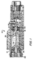
- Figure 1 is a cross-sectional side view schematically illustrating an embodiment of a vane motor rotor assembly; and
- Figure 2 is an exploded perspective view of the vane motor rotor assembly.
- In Figures 1 and 2, a fluid vane motor includes a
hollow cylinder 12 within which a rotor assembly, shown generally by 14, is disposed. The rotor assembly includes acylindrical rotor body 16 havingfront 18 and rear 20 faces. Afront shaft portion 22 and arear shaft portion 24 extend axially from the respective front and rear faces. A plurality ofradial vane slots 28 extend axially along the outer circumferential surface of the rotor body. The slots are evenly spaced around the circumference.Radial vanes 30 are slidably disposed in each radial slot such that the length of each vane is approximately equal to the length of the rotor body. The length of therotor body 16 is approximately equal to the axial length of thehollow cylinder 12. - The
rotor assembly 14 is mounted for rotation within the hollow cylinder about an axis parallel to and offset from the axis of the hollow cylinder. In other words, the rotor assembly rotates in a circular chamber eccentrically offset from the center axis of the hollow cylinder member, as is conventional for vane fluid motors. - A
rear end plate 34 having an annular shape is fixed to therear face 20 of therotor body 16 so as to close the vane slots at the rear face. In the preferred embodiment, for example, the inner diameter of the annularrear end plate 34 may be such that the rear end plate is press fit onto therear shaft 24. Alternatively, the rear end plate may be fixedly attached in a manner such as welding or may be machined as an integral part of therotor body 16. - A
front spacer member 38 has an annular shape. The inner diameter is such that the spacer member can be slid on thefront shaft 22 so as to abut thefront face 18 of therotor body 16. Since thespacer 36 rotates with therotor body 16, it could alternatively be manufactured as a stepped shoulder on thefront shaft 22. - A
front end plate 38 has a larger dimensioned annular shape such that the inner diameter of the front end plate will slide over the outer diameter of thefront spacer member 36 so as to allow relative rotation of thespacer member 36,rotor member 16, and theend plate 38. Thefront end plate 38 radially circumscribes thefront spacer member 36 and abuts thefront face 18 of therotor 16 so as to close theslots 28 at the front face. - A rear bearing 40, such as an antifriction roller bearing, is positioned on the
rear shaft 24 and is retained by means such as a press fit and aretaining ring 42. A front bearing 44 is pressed onto thefront shaft 22. The front bearing is axially positioned by thefront spacer member 36. - The
slidable vanes 30 are installed in thevane slots 28 and the completedrotor assembly 14 can now be positioned in a rotor chamber. A forward biasing means such as awave spring 46 is placed behind the rear bearing 40 to provide bias for axially locating the rotor assembly. Aclamp nut 48 is then tightened against the outer race of the front bearing to axially secure the motor parts. - The serviceable parts of the rotor of the present invention are easily accessible for maintenance by simply unscrewing
clamp nut 48 and removing therotor assembly 14. The part count compared to a typical conventional vane motor construction is less. Additionally, since the rotor assembly has an integralrear plate 34, the vanes will not slide axially when therotor assembly 14 is inserted or removed from the rotor chamber. - The
rear end plate 34 is fixed to therotor body 16 and rotates with the rotor body. Thus the rotor body is not confined on the rear end by a stationary end plate and can therefore take up axial movement or axial tolerances. - Typical steps in assembling a rotor assembly according to the present invention would be as follows: a
rear end plate 34 is pressed onto therear shaft 24 of therotor body 16. The outer diameter of the completed rotor is then ground to tolerance, therear end plate 34 being radially coextensive with therotor body 16. Therear bearing 40 is pressed onto the rear shaft and aretaining ring 42 is positioned to further retain the bearing. Thefront spacer member 36 is slid on thefront shaft 22. Thefront end plate 38 is slid over the outer diameter of thefront spacer 36 so as to circumscribe the front spacer member. The front bearing 44 is pressed onto thefront shaft 22. The inner face of the front bearing is ground flush to fit against the face of thespacer member 36 so as to provide the proper clearance between the rotating rotor and thestationary end plate 38. Vanes are disposed in each slot. - The
rotor assembly 14 is then positioned in the eccentric cylinder chamber to abut against aspring washer 46 which provides bias for forward axial bias of the rotor. Theclamp nut 48 is then tightened against the outer race of the front bearing 44 to axially secure the motor parts. Thespacer member 36 is clamped tightly between the bearing inner race and thefront face 18 of the rotor body. The inner race, spacer member and rotor body thus all rotate as a unit. A power takeoff spindle is located on thefront shaft 22 to to provide power takeoff for the rotational force developed by the motor when energized.
Claims (5)
- A rotor assembly (14) for a vane motor having
a cylindrical rotor body (16) having front (18) and rear faces (20) and front (22) and rear (24) shaft portions extending axially from the respective faces and radial slots (28) extending axially along the rotor body (16);
a front spacer member (36) positioned on the front shaft portion (22) so as to abut the front face (18) of the rotor body 16; and
a front end plate (38) radially circumscribing the front spacer member (36) so as to close the slots (28) at the front face (18) while allowing relative rotation between the spacer (36) and the front end plate (38), and a rear end plate (34) fixed at the rear face (20) of said rotor body (16) on said rear shaft (24), characterised in that said rear end plate (34) is radially co-extensive with said rotor body so as to close the slots (28) at the rear face (20). - An assembly according to claim 1, wherein said front spacer (36) is integrally formed with said front shaft portion (22).
- An assembly according to claim 1 or 2, comprising a front bearing (44) and a rear bearing (40) for rotatably supporting each respective shaft portion (22, 24).
- An assembly according to claim 1, 2 or 3, comprising radially sliding vanes (30) supported in the slots (28).
- An assembly according to any one of the preceding claims mounted in a fluid vane motor including a hollow cylinder (12) having fluid inlet and outlet ports, and the rotor assembly (14) being mounted for rotation within said cylinder (12) about an axis parallel to the axis of said cylinder.
Applications Claiming Priority (2)
| Application Number | Priority Date | Filing Date | Title |
|---|---|---|---|
| US07/325,568 US4960373A (en) | 1989-03-17 | 1989-03-17 | Fluid motor rotor assembly |
| US325568 | 1989-03-17 |
Publications (2)
| Publication Number | Publication Date |
|---|---|
| EP0388127A1 EP0388127A1 (en) | 1990-09-19 |
| EP0388127B1 true EP0388127B1 (en) | 1993-06-09 |
Family
ID=23268426
Family Applications (1)
| Application Number | Title | Priority Date | Filing Date |
|---|---|---|---|
| EP90302617A Expired - Lifetime EP0388127B1 (en) | 1989-03-17 | 1990-03-12 | Fluid motor rotor assembly |
Country Status (5)
| Country | Link |
|---|---|
| US (1) | US4960373A (en) |
| EP (1) | EP0388127B1 (en) |
| JP (1) | JP2979046B2 (en) |
| CA (1) | CA2011966C (en) |
| DE (1) | DE69001842T2 (en) |
Families Citing this family (3)
| Publication number | Priority date | Publication date | Assignee | Title |
|---|---|---|---|---|
| US5449051A (en) * | 1993-12-16 | 1995-09-12 | Liao; Pen-Huai | Pneumatic oil lubricator |
| US20090084259A1 (en) * | 2007-09-27 | 2009-04-02 | Li-Chen Chen | Pneumatic Tool |
| US11883942B2 (en) | 2020-06-24 | 2024-01-30 | Snap-On Incorporated | Flow path diverter for pneumatic tool |
Family Cites Families (9)
| Publication number | Priority date | Publication date | Assignee | Title |
|---|---|---|---|---|
| US3193190A (en) * | 1965-07-06 | Lindberg vacuum pump | ||
| US3552895A (en) * | 1969-05-14 | 1971-01-05 | Lear Siegler Inc | Dry rotary vane pump |
| US3885355A (en) * | 1972-02-19 | 1975-05-27 | Ushio Kk | Pneumatically driven grinder |
| US3826597A (en) * | 1972-10-19 | 1974-07-30 | Drum Eng Co Ltd | Compressor with cartridge assembly |
| SE418101B (en) * | 1977-01-17 | 1981-05-04 | Atlas Copco Ab | PRESSURE-DRIVE LAMEL ENGINE |
| SE7805546L (en) * | 1978-05-16 | 1979-11-17 | Atlas Copco Ab | HANDHALLET MACHINE TOOLS |
| JPS5656979A (en) * | 1979-10-17 | 1981-05-19 | Ushio Kogyo Kk | Vane type fluid motor |
| US4397620A (en) * | 1981-04-21 | 1983-08-09 | Nippon Soken, Inc. | Rotary bladed compressor with sealing gaps at the rotary ends |
| JPS59229083A (en) * | 1983-06-08 | 1984-12-22 | Nippon Denso Co Ltd | Sliding vane compressor |
-
1989
- 1989-03-17 US US07/325,568 patent/US4960373A/en not_active Expired - Lifetime
-
1990
- 1990-03-12 DE DE90302617T patent/DE69001842T2/en not_active Expired - Fee Related
- 1990-03-12 EP EP90302617A patent/EP0388127B1/en not_active Expired - Lifetime
- 1990-03-12 CA CA002011966A patent/CA2011966C/en not_active Expired - Lifetime
- 1990-03-16 JP JP2064516A patent/JP2979046B2/en not_active Expired - Fee Related
Also Published As
| Publication number | Publication date |
|---|---|
| DE69001842T2 (en) | 1993-10-21 |
| CA2011966A1 (en) | 1990-09-17 |
| DE69001842D1 (en) | 1993-07-15 |
| CA2011966C (en) | 1998-12-01 |
| EP0388127A1 (en) | 1990-09-19 |
| JPH02283868A (en) | 1990-11-21 |
| JP2979046B2 (en) | 1999-11-15 |
| US4960373A (en) | 1990-10-02 |
Similar Documents
| Publication | Publication Date | Title |
|---|---|---|
| EP0560466A3 (en) | Centrifugal blood pump and motor drive | |
| CA3061478C (en) | Magnetically engaged pump | |
| CA1059931A (en) | Apparatus and system for stabilizing the disc elements of a rotary concentrator for solids-containing fluids | |
| US5385454A (en) | Bearing device for use in a canned motor | |
| GB2082681A (en) | Drive arrangement for a rotary compressor | |
| EP0388127B1 (en) | Fluid motor rotor assembly | |
| US4898524A (en) | Fluid driven rotary motor | |
| CA2371763A1 (en) | Concentricity ring | |
| US5683185A (en) | Journal bearing retainer system with eccentric lock | |
| EP0376644B1 (en) | Radial flow fluid pressure module | |
| US5385445A (en) | Centrifugal pump | |
| US3932055A (en) | Vacuum turbine for a drill | |
| DK2994645T3 (en) | MAGNET PUMP ARRANGEMENT | |
| EP1386060B1 (en) | Turbine or compressor device and method for assembling the device | |
| US5876194A (en) | Fixed-displacement vane-type hydraulic machine | |
| GB1573881A (en) | Pneumatic sliding-vane rotary motor | |
| JPH0239638B2 (en) | ||
| US4875826A (en) | Pitot pump assembly for a rotating fluid management device | |
| US20240186854A1 (en) | Threaded rotor pressure plate | |
| JPH03249391A (en) | Turning rotor device | |
| SU984125A1 (en) | Disintegrator | |
| JPH05133347A (en) | Gear pump | |
| CA2014078A1 (en) | Centrifugal blood pump and motor drive | |
| GB1591592A (en) | Rotary pump and electric motor unit | |
| RU2002100213A (en) | GAS TURBINE ENGINE, KIT FOR ITS MOUNTING, CENTER RING AND METHOD FOR MOUNTING A GAS TURBINE ENGINE |
Legal Events
| Date | Code | Title | Description |
|---|---|---|---|
| PUAI | Public reference made under article 153(3) epc to a published international application that has entered the european phase |
Free format text: ORIGINAL CODE: 0009012 |
|
| AK | Designated contracting states |
Kind code of ref document: A1 Designated state(s): DE FR GB IT SE |
|
| 17P | Request for examination filed |
Effective date: 19901206 |
|
| 17Q | First examination report despatched |
Effective date: 19911119 |
|
| GRAA | (expected) grant |
Free format text: ORIGINAL CODE: 0009210 |
|
| AK | Designated contracting states |
Kind code of ref document: B1 Designated state(s): DE FR GB IT SE |
|
| REF | Corresponds to: |
Ref document number: 69001842 Country of ref document: DE Date of ref document: 19930715 |
|
| ITF | It: translation for a ep patent filed | ||
| ET | Fr: translation filed | ||
| PLBE | No opposition filed within time limit |
Free format text: ORIGINAL CODE: 0009261 |
|
| STAA | Information on the status of an ep patent application or granted ep patent |
Free format text: STATUS: NO OPPOSITION FILED WITHIN TIME LIMIT |
|
| 26N | No opposition filed | ||
| EAL | Se: european patent in force in sweden |
Ref document number: 90302617.7 |
|
| REG | Reference to a national code |
Ref country code: GB Ref legal event code: IF02 |
|
| PGFP | Annual fee paid to national office [announced via postgrant information from national office to epo] |
Ref country code: DE Payment date: 20080430 Year of fee payment: 19 Ref country code: FR Payment date: 20080317 Year of fee payment: 19 |
|
| PGFP | Annual fee paid to national office [announced via postgrant information from national office to epo] |
Ref country code: IT Payment date: 20080329 Year of fee payment: 19 |
|
| PGFP | Annual fee paid to national office [announced via postgrant information from national office to epo] |
Ref country code: SE Payment date: 20090327 Year of fee payment: 20 |
|
| PGFP | Annual fee paid to national office [announced via postgrant information from national office to epo] |
Ref country code: GB Payment date: 20090403 Year of fee payment: 20 |
|
| REG | Reference to a national code |
Ref country code: FR Ref legal event code: ST Effective date: 20091130 |
|
| PG25 | Lapsed in a contracting state [announced via postgrant information from national office to epo] |
Ref country code: DE Free format text: LAPSE BECAUSE OF NON-PAYMENT OF DUE FEES Effective date: 20091001 |
|
| REG | Reference to a national code |
Ref country code: GB Ref legal event code: PE20 Expiry date: 20100311 |
|
| PG25 | Lapsed in a contracting state [announced via postgrant information from national office to epo] |
Ref country code: FR Free format text: LAPSE BECAUSE OF NON-PAYMENT OF DUE FEES Effective date: 20091123 |
|
| EUG | Se: european patent has lapsed | ||
| PG25 | Lapsed in a contracting state [announced via postgrant information from national office to epo] |
Ref country code: GB Free format text: LAPSE BECAUSE OF EXPIRATION OF PROTECTION Effective date: 20100311 |
|
| PG25 | Lapsed in a contracting state [announced via postgrant information from national office to epo] |
Ref country code: IT Free format text: LAPSE BECAUSE OF NON-PAYMENT OF DUE FEES Effective date: 20090312 |