EP0388085A2 - Druckknopfschalter mit einer Verriegelungsvorrichtung - Google Patents
Druckknopfschalter mit einer Verriegelungsvorrichtung Download PDFInfo
- Publication number
- EP0388085A2 EP0388085A2 EP90302502A EP90302502A EP0388085A2 EP 0388085 A2 EP0388085 A2 EP 0388085A2 EP 90302502 A EP90302502 A EP 90302502A EP 90302502 A EP90302502 A EP 90302502A EP 0388085 A2 EP0388085 A2 EP 0388085A2
- Authority
- EP
- European Patent Office
- Prior art keywords
- push
- lever
- buttons
- button
- pin
- Prior art date
- Legal status (The legal status is an assumption and is not a legal conclusion. Google has not performed a legal analysis and makes no representation as to the accuracy of the status listed.)
- Granted
Links
Images

Classifications
-
- H—ELECTRICITY
- H01—ELECTRIC ELEMENTS
- H01H—ELECTRIC SWITCHES; RELAYS; SELECTORS; EMERGENCY PROTECTIVE DEVICES
- H01H13/00—Switches having rectilinearly-movable operating part or parts adapted for pushing or pulling in one direction only, e.g. push-button switch
- H01H13/70—Switches having rectilinearly-movable operating part or parts adapted for pushing or pulling in one direction only, e.g. push-button switch having a plurality of operating members associated with different sets of contacts, e.g. keyboard
- H01H13/72—Switches having rectilinearly-movable operating part or parts adapted for pushing or pulling in one direction only, e.g. push-button switch having a plurality of operating members associated with different sets of contacts, e.g. keyboard wherein the switch has means for limiting the number of operating members that can concurrently be in the actuated position
- H01H13/74—Switches having rectilinearly-movable operating part or parts adapted for pushing or pulling in one direction only, e.g. push-button switch having a plurality of operating members associated with different sets of contacts, e.g. keyboard wherein the switch has means for limiting the number of operating members that can concurrently be in the actuated position each contact set returning to its original state only upon actuation of another of the operating members
-
- Y—GENERAL TAGGING OF NEW TECHNOLOGICAL DEVELOPMENTS; GENERAL TAGGING OF CROSS-SECTIONAL TECHNOLOGIES SPANNING OVER SEVERAL SECTIONS OF THE IPC; TECHNICAL SUBJECTS COVERED BY FORMER USPC CROSS-REFERENCE ART COLLECTIONS [XRACs] AND DIGESTS
- Y10—TECHNICAL SUBJECTS COVERED BY FORMER USPC
- Y10T—TECHNICAL SUBJECTS COVERED BY FORMER US CLASSIFICATION
- Y10T74/00—Machine element or mechanism
- Y10T74/20—Control lever and linkage systems
- Y10T74/20207—Multiple controlling elements for single controlled element
- Y10T74/20238—Interlocked
- Y10T74/20244—Push button
Definitions
- This invention relates to a push-button switch having an interlocking device.
- an interlocking device which prevents two push-buttons from being pushed down simultaneously is required in order to avoid breaking of the switch caused by simultaneous operation of two push-buttons.
- This earlier interlocking system is complicated in construction, has many component parts and is troublesome to assemble, especially where springs and balls are employed in the switches.
- a push-button switch device comprising a switch body in which two push-buttons are mounted side by side for guided sliding movement parallel to each other, an interlocking lever extending between the push-buttons and having its opposite ends in engagement with the two push-buttons respectively whereby the ends of the lever move with the respective push-buttons and are capable of a degree of pivotal movement relative to the push-buttons, the lever having at its side further from the tops of the push-buttons and mid-way between it ends a projection which co-operates with a pin mounted in the body and extending transversely of the lever, the arrangement being such that when either of the push- buttons is depressed the lever is caused to swivel about its end engaged with the other push-button so that said projection moves round the side of the pin remote from the push-button being depressed the engagement between the pin and the lever preventing the other push-button from being depressed.
- two holes 1a in which push-buttons 2 are slidably mounted side by side are provided in the switch body 1.
- a vertical guide groove 1b for guiding a guide ball 3 for two-step operation is provided in the upper part of the wall of each hole 1a. The guide ball 3 is led into the hole 1a from the guide groove 1b.
- Each push-button 2 is of such shape as to be slidable vertically in the corresponding hole 1a in the switch body.
- Each guide ball 3 is disposed in a lateral hole 2a in the push-button and is urged outward against the surface of the guide groove 1b by the biasing force of a spring 4 disposed in the hole 2a and seated against the blanked-off bottom of the hole 2a.
- a central hole 2b extends upward from the bottom of the push-button 2 and a spring 5 is interposed between the upper end of the hole 2b and the bottom of the hole 1a in the switch body 1 so that the push-button 2 is urged resiliently upward by the spring 5.
- the push button 2 is restrained by movable contact pieces S1, S2 which extend through the push-button 2 laterally and move toward and away from fixed contact pieces T1, T2 fixed to the side of the switch body.
- a slot 10 is formed in the top surface of the switch body 1 in such a fashion that it interconnects the two parallel holes 1a, and journal grooves 11 in which a cylindrical pin 12 is rotatably mounted to extend transversely of the slot 10 are formed substantially centrally of opposite surfaces of the slot 10.
- a locking lever 13 is disposed in the groove 10.
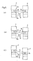
- the lever 13, as shown in Figures 1 and 5, has a projecting fulcrum 13a of triangular shape at the centre of its lower surface. This fulcrum 13a makes contact with the top of the periphery of the pin 12.
- Figure 5 (A) shows the OFF state where neither of both push-buttons 2 is depressed.
- the right-hand push-button 2 is pushed down a short distance (i.e. a first step) as shown in Figure 5 (B)
- the lever 13 tilts to the right about its fulcrum 13a.
- depression of the left-hand push-button is impossible because the fulcrum 13a is in abutment with the pin 12.
- the left-hand push-button 2 is in a locked state.
- the preferred embodiment is simple in construction and makes it possible to carry out interlocking of the push-buttons in each of two stages of operation.
Landscapes
- Push-Button Switches (AREA)
- Switch Cases, Indication, And Locking (AREA)
- Mechanisms For Operating Contacts (AREA)
Applications Claiming Priority (2)
| Application Number | Priority Date | Filing Date | Title |
|---|---|---|---|
| JP65169/89 | 1989-03-17 | ||
| JP1065169A JPH0734339B2 (ja) | 1989-03-17 | 1989-03-17 | 押釦スイッチのインターロック装置 |
Publications (3)
| Publication Number | Publication Date |
|---|---|
| EP0388085A2 true EP0388085A2 (de) | 1990-09-19 |
| EP0388085A3 EP0388085A3 (de) | 1991-10-02 |
| EP0388085B1 EP0388085B1 (de) | 1995-05-17 |
Family
ID=13279120
Family Applications (1)
| Application Number | Title | Priority Date | Filing Date |
|---|---|---|---|
| EP90302502A Expired - Lifetime EP0388085B1 (de) | 1989-03-17 | 1990-03-08 | Druckknopfschalter mit einer Verriegelungsvorrichtung |
Country Status (5)
| Country | Link |
|---|---|
| US (1) | US5045647A (de) |
| EP (1) | EP0388085B1 (de) |
| JP (1) | JPH0734339B2 (de) |
| CA (1) | CA2011960C (de) |
| DE (1) | DE69019405T2 (de) |
Cited By (1)
| Publication number | Priority date | Publication date | Assignee | Title |
|---|---|---|---|---|
| US5652324A (en) * | 1994-11-21 | 1997-07-29 | Bayer Aktiengesellschaft | Process for the production of thermoplastic polycarbonate |
Families Citing this family (15)
| Publication number | Priority date | Publication date | Assignee | Title |
|---|---|---|---|---|
| JPH0648611B2 (ja) * | 1990-11-22 | 1994-06-22 | 新晃電機株式会社 | 押釦スイッチのインターロック装置 |
| JP2589610Y2 (ja) * | 1991-01-17 | 1999-02-03 | 富士電機 株式会社 | 電磁接触器の相互鎖錠装置 |
| JP2923736B2 (ja) * | 1994-08-18 | 1999-07-26 | 春日電機株式会社 | 多段階操作インタ−ロック付押釦開閉器 |
| JP3210876B2 (ja) * | 1997-02-10 | 2001-09-25 | 新晃電機株式会社 | 押釦スイッチのインターロック装置 |
| JP2961098B2 (ja) * | 1997-04-14 | 1999-10-12 | 新晃電機株式会社 | 押釦スイッチのインターロック装置 |
| US6204992B1 (en) | 1998-06-11 | 2001-03-20 | Advanced Digital Information Corporation | Data cartridge loading and unloading apparatus and method of use |
| US6157026A (en) * | 1998-11-19 | 2000-12-05 | Maxtec International Corporation | Optical switch of the multiple push button type for producing a plurality of control signals |
| US6201905B1 (en) | 1999-02-05 | 2001-03-13 | Telemotive Industrial Controls | Optical switch with controlled voltage output |
| JP3866022B2 (ja) * | 2000-07-31 | 2007-01-10 | アルプス電気株式会社 | 操作装置 |
| KR20050066493A (ko) * | 2003-12-26 | 2005-06-30 | 엘지전자 주식회사 | 세탁기 조작 패널의 버튼 구조 |
| CN104916475A (zh) * | 2015-07-02 | 2015-09-16 | 常州市宇声电子有限公司 | 一种多方位新型墙壁开关 |
| CN104992864A (zh) * | 2015-07-02 | 2015-10-21 | 常州市宇声电子有限公司 | 一种新型墙壁开关 |
| TWI669046B (zh) * | 2015-08-14 | 2019-08-11 | 佳能企業股份有限公司 | 閉鎖結構及應用其之系統 |
| CN109192575B (zh) * | 2018-10-22 | 2019-10-11 | 安徽银点电子科技有限公司 | 一种按压式触点开关 |
| JP6932884B2 (ja) * | 2019-03-29 | 2021-09-08 | 新晃電機株式会社 | イネーブルスイッチ |
Citations (4)
| Publication number | Priority date | Publication date | Assignee | Title |
|---|---|---|---|---|
| US1351161A (en) * | 1919-02-07 | 1920-08-31 | Fagerlund Erik Artur | Switch |
| GB426094A (en) * | 1934-03-14 | 1935-03-27 | Vedder Gmbh Geb | Improvements in or relating to snap-action electric switches |
| GB1155059A (en) * | 1965-12-17 | 1969-06-18 | Square D Co | Interlock Dual Push Button Electric Switch Operator Assembly |
| DE7515843U (de) * | 1975-05-17 | 1975-09-04 | Trix Mangold Gmbh & Co | Schaltvorrichtung mit einer Schaltwippe |
Family Cites Families (5)
| Publication number | Priority date | Publication date | Assignee | Title |
|---|---|---|---|---|
| US2523786A (en) * | 1947-09-02 | 1950-09-26 | Soreng Mfg Corp | Electrical switch |
| US2713092A (en) * | 1951-03-23 | 1955-07-12 | Furnas Electric Co | Push button switch assemblage |
| US3674948A (en) * | 1971-02-02 | 1972-07-04 | Bell & Howell Co | Control mechanism having cycle switches selectively actuating a mode switch |
| DE7926469U1 (de) * | 1979-09-18 | 1979-12-13 | Siemens Ag, 1000 Berlin Und 8000 Muenchen | Verriegelungseinrichtung für Kontaktträger |
| JPH0732551A (ja) * | 1993-07-21 | 1995-02-03 | Dainippon Printing Co Ltd | 剥離シート |
-
1989
- 1989-03-17 JP JP1065169A patent/JPH0734339B2/ja not_active Expired - Lifetime
-
1990
- 1990-03-08 DE DE69019405T patent/DE69019405T2/de not_active Expired - Lifetime
- 1990-03-08 EP EP90302502A patent/EP0388085B1/de not_active Expired - Lifetime
- 1990-03-09 US US07/491,426 patent/US5045647A/en not_active Expired - Lifetime
- 1990-03-12 CA CA002011960A patent/CA2011960C/en not_active Expired - Lifetime
Patent Citations (4)
| Publication number | Priority date | Publication date | Assignee | Title |
|---|---|---|---|---|
| US1351161A (en) * | 1919-02-07 | 1920-08-31 | Fagerlund Erik Artur | Switch |
| GB426094A (en) * | 1934-03-14 | 1935-03-27 | Vedder Gmbh Geb | Improvements in or relating to snap-action electric switches |
| GB1155059A (en) * | 1965-12-17 | 1969-06-18 | Square D Co | Interlock Dual Push Button Electric Switch Operator Assembly |
| DE7515843U (de) * | 1975-05-17 | 1975-09-04 | Trix Mangold Gmbh & Co | Schaltvorrichtung mit einer Schaltwippe |
Cited By (1)
| Publication number | Priority date | Publication date | Assignee | Title |
|---|---|---|---|---|
| US5652324A (en) * | 1994-11-21 | 1997-07-29 | Bayer Aktiengesellschaft | Process for the production of thermoplastic polycarbonate |
Also Published As
| Publication number | Publication date |
|---|---|
| CA2011960C (en) | 1995-01-10 |
| DE69019405T2 (de) | 1996-02-29 |
| EP0388085A3 (de) | 1991-10-02 |
| JPH02244520A (ja) | 1990-09-28 |
| CA2011960A1 (en) | 1990-09-17 |
| DE69019405D1 (de) | 1995-06-22 |
| JPH0734339B2 (ja) | 1995-04-12 |
| EP0388085B1 (de) | 1995-05-17 |
| US5045647A (en) | 1991-09-03 |
Similar Documents
| Publication | Publication Date | Title |
|---|---|---|
| EP0388085A2 (de) | Druckknopfschalter mit einer Verriegelungsvorrichtung | |
| EP0663677B1 (de) | Schalteranordnung | |
| US4733882A (en) | Push rod for baby carriage | |
| US5920042A (en) | Seesaw sliding composite motion switch | |
| US4121065A (en) | Toggle switch lever lock | |
| US4733035A (en) | Switch with device for preventing erroneous operation | |
| EP0142593A1 (de) | Tastaturschalter mit drehbar gelagertem Betätigungshebel | |
| US4347415A (en) | Electric quick-break switch with forced opening of the contacts | |
| US6207915B1 (en) | Reset mechanism for canceling locked state in a push-button switch | |
| US4417115A (en) | Switch actuating assembly having improved cams and plural modes | |
| US4433222A (en) | Miniaturized push button switch | |
| JP4391436B2 (ja) | 3ポジションスイッチ | |
| US4371763A (en) | Inerita switch device | |
| CA1312896C (en) | Pushbutton switch, particularly key switch | |
| GB2185854A (en) | Push button multi-contact electric switches | |
| US5233140A (en) | Multiple switch assembly with interlock | |
| US4640998A (en) | Push button switch with compound contact lever action | |
| US4795860A (en) | Push switch | |
| US4385214A (en) | Interlock pushbutton assembly | |
| EP0348202A2 (de) | Elektrische Schalteinrichtungen | |
| CA1130354A (en) | Manually operable switch | |
| US3492882A (en) | Switch actuator | |
| US3280277A (en) | Quick acting switch | |
| JPH0527784Y2 (de) | ||
| JPH054670Y2 (de) |
Legal Events
| Date | Code | Title | Description |
|---|---|---|---|
| PUAI | Public reference made under article 153(3) epc to a published international application that has entered the european phase |
Free format text: ORIGINAL CODE: 0009012 |
|
| AK | Designated contracting states |
Kind code of ref document: A2 Designated state(s): DE FR GB |
|
| PUAL | Search report despatched |
Free format text: ORIGINAL CODE: 0009013 |
|
| AK | Designated contracting states |
Kind code of ref document: A3 Designated state(s): DE FR GB |
|
| 17P | Request for examination filed |
Effective date: 19911114 |
|
| 17Q | First examination report despatched |
Effective date: 19931027 |
|
| GRAA | (expected) grant |
Free format text: ORIGINAL CODE: 0009210 |
|
| AK | Designated contracting states |
Kind code of ref document: B1 Designated state(s): DE FR GB |
|
| ET | Fr: translation filed | ||
| REF | Corresponds to: |
Ref document number: 69019405 Country of ref document: DE Date of ref document: 19950622 |
|
| PLBE | No opposition filed within time limit |
Free format text: ORIGINAL CODE: 0009261 |
|
| STAA | Information on the status of an ep patent application or granted ep patent |
Free format text: STATUS: NO OPPOSITION FILED WITHIN TIME LIMIT |
|
| 26N | No opposition filed | ||
| REG | Reference to a national code |
Ref country code: GB Ref legal event code: IF02 |
|
| PGFP | Annual fee paid to national office [announced via postgrant information from national office to epo] |
Ref country code: GB Payment date: 20090318 Year of fee payment: 20 |
|
| PGFP | Annual fee paid to national office [announced via postgrant information from national office to epo] |
Ref country code: DE Payment date: 20090527 Year of fee payment: 20 |
|
| PGFP | Annual fee paid to national office [announced via postgrant information from national office to epo] |
Ref country code: FR Payment date: 20090313 Year of fee payment: 20 |
|
| REG | Reference to a national code |
Ref country code: GB Ref legal event code: PE20 Expiry date: 20100307 |
|
| PG25 | Lapsed in a contracting state [announced via postgrant information from national office to epo] |
Ref country code: GB Free format text: LAPSE BECAUSE OF EXPIRATION OF PROTECTION Effective date: 20100307 |
|
| PG25 | Lapsed in a contracting state [announced via postgrant information from national office to epo] |
Ref country code: DE Free format text: LAPSE BECAUSE OF EXPIRATION OF PROTECTION Effective date: 20100308 |