EP0387632A2 - Cutting and winding device for bands - Google Patents
Cutting and winding device for bands Download PDFInfo
- Publication number
- EP0387632A2 EP0387632A2 EP90104077A EP90104077A EP0387632A2 EP 0387632 A2 EP0387632 A2 EP 0387632A2 EP 90104077 A EP90104077 A EP 90104077A EP 90104077 A EP90104077 A EP 90104077A EP 0387632 A2 EP0387632 A2 EP 0387632A2
- Authority
- EP
- European Patent Office
- Prior art keywords
- winding
- film
- cutting
- strips
- web
- Prior art date
- Legal status (The legal status is an assumption and is not a legal conclusion. Google has not performed a legal analysis and makes no representation as to the accuracy of the status listed.)
- Granted
Links
Images
Classifications
-
- B—PERFORMING OPERATIONS; TRANSPORTING
- B65—CONVEYING; PACKING; STORING; HANDLING THIN OR FILAMENTARY MATERIAL
- B65H—HANDLING THIN OR FILAMENTARY MATERIAL, e.g. SHEETS, WEBS, CABLES
- B65H19/00—Changing the web roll
- B65H19/22—Changing the web roll in winding mechanisms or in connection with winding operations
-
- B—PERFORMING OPERATIONS; TRANSPORTING
- B65—CONVEYING; PACKING; STORING; HANDLING THIN OR FILAMENTARY MATERIAL
- B65H—HANDLING THIN OR FILAMENTARY MATERIAL, e.g. SHEETS, WEBS, CABLES
- B65H2301/00—Handling processes for sheets or webs
- B65H2301/50—Auxiliary process performed during handling process
- B65H2301/51—Modifying a characteristic of handled material
- B65H2301/513—Modifying electric properties
- B65H2301/5133—Removing electrostatic charge
Definitions
- the invention relates to a cutting and winding device for film strips, in which, following a slitting station for cutting film strips from a web, the film strips arranged essentially in a horizontal row are guided to a winding or winding unit. It also relates to a method for changing the spool or winding core when winding up the film strips.
- a continuous film web of constant width is cut into individual film strips. This is done with the help of a row of stationary separating knives arranged perpendicular to the web running direction, which are equally spaced from one another and protrude into the web with their cutting edges directed against the web movement.
- the finished film strips are then individually wound onto spools or flangeless winding cores on a winding unit.
- the individual winding units can be arranged in a row one behind the other or next to one another in the running direction of the film strips, or if there are a large number of film strips to be wound up, several rows of winding units can also be arranged one above the other in tiers.
- DE 34 14 636 describes a method for changing bobbins, in which the amount of waste which is to be reduced when winding up several rows of winding units which are arranged one behind the other.
- a cutting and winding device is known, in which the separate film strips are wound onto cores which are firmly connected to a winding shaft, and four winding shafts are present within a winding star, which are axially displaceable and one denaturing and one Assembly device can be supplied, which simultaneously takes care of the removal of one winding shaft from winding cores and the loading of another shaft with new winding cores.
- a reel cutting and winding machine for film strips is known, in which, following a longitudinal cutting station for cutting web strips from a web, a separation station is provided for separating adjacent web strips into separate winding axes, with alignment combs in the longitudinal grooves of each winding axis radial alignment edges are adjustably arranged, which position the winding tubes.
- a corresponding device is known in which, following a slitting station for cutting strips of film from a web, the films on individual Winding cores are guided and each winding core is assigned a drive roller resting on the circumference of the winding.
- winding devices for cut web strips are known, in which the strips are guided over a so-called spreading comb, which are pins which deflect the film strips in different directions and the strips are wound up with a device according to DE 23 65 606 mentioned above.
- this requires extensive effort when changing the bobbin as soon as the full winding circumference is reached.
- a 65 cm wide magnetic tape web is cut lengthways into 3.81 mm wide strips, which are wound on winding cores, around 170 tape windings have to be glued at the end and removed from the winding axis, after which these winding axes are newly fitted with cores, on which then the beginnings of the film strips must be attached.
- This can mean a considerable changeover time, which is about as long as the winding time.
- a further work step arises from the fact that the finished tape rolls may have to be provided with intermediate layers for transport and stacked on top of each other in larger containers.
- the device described above takes up a considerable amount of space. Therefore, the task was to find a winding device of the generic type mentioned above, which - is compact - Significantly reduced changeover times when changing the winding - already delivers ready-to-ship packages.
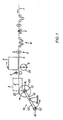
- Figure 1 shows schematically the side view of a preferred embodiment of the device according to the invention.
- the film web (1) coming from a casting or extrusion device (not shown) is fed in the direction of the arrow via a cross cutting device (2) to be described further below, and subsequently via a loop puller (8) to compensate for the web voltage fluctuations.
- the web is subsequently cut lengthwise into narrow strips (4) by means of a separating knife arrangement (9), the axis of which is arranged perpendicular to the direction of the film web, or a reel cutter.
- a separating knife arrangement 9
- Such arrangements are known from numerous publications, for example from DE 24 05 849 or DE 37 01 716 from the applicant, where in particular arrangements for cutting magnetic tape webs in film strips are described.
- the cut strips are passed between a pivotable pressure roller (6), the width of which is at least as large as the entire width of the film web, and a guide suction comb (3).
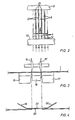
- the suction comb consists (FIG. 2) of a number of vertically arranged segments (5), the number and width of which corresponds to the number and width of the film strips and which can be subjected to negative pressure. The segments are spaced from each other. The suction comb is laterally pivotable in the film running direction.
- the winding of the film strips (4) is accomplished by a rotatable winding device (10) consisting of at least two arms (12, 12 '), at the free ends of which a drivable shaft (13, 13') is located as the winding axis.
- a rotatable winding device consisting of at least two arms (12, 12 '), at the free ends of which a drivable shaft (13, 13') is located as the winding axis.
- flange coils or flangeless winding cores 14, 14 '
- Flange-less winding cores and particularly preferably stackable winding cores according to DE 24 48 853 are preferred for winding according to the device according to the invention, which are stacked on top of one another so that they are tensioned on a winding shaft in such a way that the windings or the winding surfaces lie practically spaced apart.
- the cross-cutting device (2) already mentioned is used to produce a defined strip length, one strip length being provided with the following one with a specific adhesive point.
- this device consists in a preferred embodiment of a three-part cutting table. This has two fixed parallel support rails (16, 17) transverse to the film running direction and a narrow movable support rail (18) arranged between them. Between the two columns of the rails (16, 17) and the vertically displaceable rail (18), two cutting wheels (15, 15 ') or cutting knife blades for cross-cutting the web (1) can be immersed.
- adhesive tape (22) for connecting the two separate web pieces a tape provided with an adhesive surface is preferably used, the two lateral ends (19, 19 ') of which are turned away from the adhesive surface (20), are bent at an obtuse angle and are free of adhesive (FIG. 4).
- the cutting table can consist of only two support rails, with one there between the gap, a rail being horizontally displaced after the separation of the web by the width of the rail (18) and the adhesive connection subsequently being produced.
- the adhesive tape (22) can also have only one glue-free, bent end.
- the full tape windings (23) wound on the winding cores (14) are each with an adhesive tape (22) on the outer circumference of the tape winding.
- the roller (6) is then pivoted onto the suction comb (3), the segments (5) of which are subjected to negative pressure, so that they suck in the film strips (4).
- the rotatable roller (6) is wetted on its cylindrical surface (24) with a liquid, for example water, for moistening the underside of the film web strips.
- the cutting wheel (7) is lowered onto the film level and the film strips (4) are cut off transversely to the web direction. This leaves from the glue point (22) to the end of the film a film residue (4 ') of 5 to 20 cm, from the interface to the beginning of the suction comb (3) about 5 to 10 cm.
- the winding device (10) rotates through 180 °, so that now on the winding shaft (13 ') already unwound cores (14') are located adjacent to the suction comb.
- the roller (6) is pivoted away from the suction comb, whereupon the latter with the held strip ends (4) the winding shaft (13 ') with the cores (14') is pivoted to a small distance, so that it reaches the position shown in dashed lines in Figure 1.
- On the winding cores (14 ') now come the moistened undersides of the ends of the cut strips (4) to lie.
- the empty cores (14 ') may have been moistened beforehand by an appropriate device.
- the outer periphery of the intermediate layer foils (21) provided between the winding cores can dip into the open gaps (25) between the segments (5) of the guide suction comb (3). This can be facilitated by the winding shaft (13 ') starting up briefly, for example, and the intermediate layers being tightened as a result of centrifugal force.
- the winding shaft (13 ') is slowly driven then faster and the winding process begins, while at the same time the negative pressure is removed from the segments (5).
- the suction comb is either suddenly or gradually pivoted away with the winding diameter (23 ') of the newly emerging tape roll and returns to its original position ( Figure 1).
- the high speed up to about 1000 m / min. can take place, on the arm (12) of the device (10) all finished tape rolls (23) can be completely removed as a unit and packed ready for dispatch, for example in a packaging unit according to DE-PS 26 55 254 or DE-GM 87 16 579 and 87 16 580 or 88 03 062 from the applicant.
- the shaft (13) is then re-equipped with empty winding cores.
- a defined strip length of the film web is expediently formed by the cross cutting already described direction (2). This is done by cutting the foil web at certain intervals on this device with the cutting wheels (15, 15 ') while the web is stationary, then the support rail is moved downwards and the narrow piece of tape located on it is removed in some way. Then an adhesive tape (22) is applied and the two tape ends are connected to one another by the adhesive surface (20). There is a short distance between the tape ends, which can be a few millimeters to a few centimeters. If this glue point reaches the tape roll on the winding shaft (13 or 13 '), the tape end sticks and the winding process is ended. It can then be continued in a new cycle as described above.
- the processor can then, for example for the purpose of loading or winding magnetic tape and cassettes, easily open the gluing points for each magnetic tape roll, the so-called pancake at the protruding end of the gluing point, remove the short film residues (4 ') and then according to the magnetic tape strips in loader or winder introduce the known prior art.
Abstract
Beschrieben ist eine Vorrichtung zum schnellen Spulenwechsel beim Aufwickeln von durch Führung einer fortlaufenden Folienbahn durch eine Trennvorrichtung erzeugten Folienstreifen, wobei die Streifen von einem mit Segmenten (5) versehenen Saugkamm (3) angesaugt werden, gegen den eine anschwenkbare Walze (6) gedrückt wird und welcher die Folienstreifen ansaugt, worauf der Saugkamm auf eine mit Wickelkernen (14) bestückte Wickelwelle (13) angeschwenkt wird, welche die Enden der abgeschnittenen Folienstreifen aufnehmen, worauf der volle Bandwickel (23) hergestellt wird. Darauf wird die Aufwickelvorrichtung (10) um 180° geschwenkt und eine bereits fertig bestückte neue Wickelwelle (13') wird zum Neubewickeln vorbereitet.The invention relates to a device for quickly changing bobbins when winding up film strips produced by guiding a continuous film web through a separating device, the strips being sucked in by a suction comb (3) provided with segments (5), against which a pivotable roller (6) is pressed and which sucks the film strips, whereupon the suction comb is pivoted onto a winding shaft (13) equipped with winding cores (14), which receive the ends of the cut film strips, whereupon the full tape winding (23) is produced. The winding device (10) is then pivoted through 180 ° and a new winding shaft (13 ') which has already been fitted is prepared for new winding.
Description
Die Erfindung betrifft eine Schneide- und Wickelvorrichtung für Folienstreifen, bei der im Anschluß an eine Längsschneide-Station zum Schneiden von Folienstreifen aus einer Bahn die im wesentlichen in einer horizontalen Reihe angeordneten Folienstreifen zu einer Aufspul- beziehungsweise Wickeleinheit geführt werden. Sie betrifft ferner ein Verfahren zum Spulen- beziehungsweise Wickelkernwechsel beim Aufwickeln der Folienstreifen.The invention relates to a cutting and winding device for film strips, in which, following a slitting station for cutting film strips from a web, the film strips arranged essentially in a horizontal row are guided to a winding or winding unit. It also relates to a method for changing the spool or winding core when winding up the film strips.
Bei den bekannten Anlagen zur Herstellung von Folienstreifen wird eine fortlaufende Folienbahn von gleichbleibender Breite zu einzelnen Folienstreifen zerschnitten. Dies geschieht mit Hilfe einer senkrecht zur Bahnlaufrichtung angeordneten Reihe ortsfester Trennmesser, die zueinander gleichen Abstand haben und mit ihren gegen die Bahnbewegung gerichteten Schneiden in die Bahn hineinragen. Die fertigen Folienstreifen werden dann einzeln auf einer Aufspuleinheit auf Spulen oder flanschlose Wickelkerne aufgewickelt. Dabei können die einzelnen Aufspuleinheiten in Laufrichtung der Folienstreifen in einer Reihe hintereinander oder nebeneinander angeordnet oder bei einer größeren Zahl aufzuwickelnder Folienstreifen können auch mehrere Reihen von Aufspuleinheiten in Etagen übereinander angeordnet sein.In the known systems for the production of film strips, a continuous film web of constant width is cut into individual film strips. This is done with the help of a row of stationary separating knives arranged perpendicular to the web running direction, which are equally spaced from one another and protrude into the web with their cutting edges directed against the web movement. The finished film strips are then individually wound onto spools or flangeless winding cores on a winding unit. The individual winding units can be arranged in a row one behind the other or next to one another in the running direction of the film strips, or if there are a large number of film strips to be wound up, several rows of winding units can also be arranged one above the other in tiers.
Wenn die Spulen beziehungsweise Bandwickel ihren vorgesehenen Durchmesser erreicht haben, wird ein Spulenwechsel erforderlich. Hierzu werden die einzelnen Folienstreifen von ihren jeweiligen Spulen abgetrennt. Dann wird die volle Spule abgenommen und ein Leerkern aufgesteckt, worauf der jeweilige Folienstreifen zum weiteren Aufwickeln wieder angelegt wird. Wesentliche Nachteile dieser Art des Spulenwechselvorganges ist die dabei entstehende Abfallmenge sowie die erhebliche Umrüst- und Wechselzeit.When the spools or tape windings have reached their intended diameter, a spool change is required. For this, the individual film strips separated from their respective coils. Then the full bobbin is removed and an empty core is plugged on, whereupon the respective film strip is put on again for further winding. The main disadvantages of this type of bobbin changing process are the amount of waste generated and the considerable changeover and changing time.
Aus zahlreichen Veröffentlichungen sind Verfahren beziehungsweise Vorrichtungen bekannt, die diese Nachteile beseitigen sollen. So wird in der DE 34 14 636 ein Verfahren zum Spulenwechsel beschrieben, bei dem die Abfallmenge, welche beim Aufspulen mehrerer Reihen von Aufspuleinheiten, welche hintereinander angeordnet sind reduziert werden soll. Aus der DE 34 18 741 ist eine Schneid- und Wickelvorrichtung bekannt, bei der jeweils die getrennten Folienstreifen auf fest mit einer Wickelwelle verbundene Kerne aufgewickelt werden und wobei jeweils vier Wickelwellen innerhalb eines Wickelsterns vorhanden sind, welche axial verschiebbar sind und einer Entstückungs- sowie einer Bestückungseinrichtung zugeführt werden können, welche gleichzeitig die Entstückung einer Wickelwelle von Wickelkernen und die Bestückung einer anderen Welle mit neuen Wickelkernen besorgt. Aus der DE 23 46 330 ist eine Rollenschneid- und Wickelmaschine für Folienstreifen bekannt, bei der im Anschluß an eine Längsschneidestation zum Schneiden von Bahnstreifen aus einer Bahn eine Trennstation zum Auseinanderführen jeweils benachbarter Bahnstreifen zu gesonderten Wickelachsen vorgesehen ist, wobei in Längsnuten jeder Wickelachse Ausrichtkämme mit radialen Ausrichtkanten verstellbar angeordnet sind, welche die Wickelhülsen positionieren. Aus der DE 23 65 606 ist eine entsprechende Vorrichtung bekannt, bei der im Anschluß an eine Längsschneidestation zum Schneiden von Folienstreifen aus einer Bahn die Folien auf einzelne Wickelkerne geführt werden und wobei jedem Wickelkern eine auf dem Umfang des Wickels aufliegende Antriebsrolle zugeordnet ist.Methods and devices are known from numerous publications which are intended to eliminate these disadvantages. DE 34 14 636 describes a method for changing bobbins, in which the amount of waste which is to be reduced when winding up several rows of winding units which are arranged one behind the other. From DE 34 18 741 a cutting and winding device is known, in which the separate film strips are wound onto cores which are firmly connected to a winding shaft, and four winding shafts are present within a winding star, which are axially displaceable and one denaturing and one Assembly device can be supplied, which simultaneously takes care of the removal of one winding shaft from winding cores and the loading of another shaft with new winding cores. From DE 23 46 330 a reel cutting and winding machine for film strips is known, in which, following a longitudinal cutting station for cutting web strips from a web, a separation station is provided for separating adjacent web strips into separate winding axes, with alignment combs in the longitudinal grooves of each winding axis radial alignment edges are adjustably arranged, which position the winding tubes. From DE 23 65 606 a corresponding device is known in which, following a slitting station for cutting strips of film from a web, the films on individual Winding cores are guided and each winding core is assigned a drive roller resting on the circumference of the winding.
Ferner sind Wickelvorrichtungen für geschnittene Bahnstreifen bekannt, bei denen die Streifen über einen sogenannten Spreizkamm geführt werden, das sind Stifte, die die Folienstreifen in verschiedene Richtungen ablenken und wobei die Streifen mit einer Vorrichtung gemäß der oben genannten DE 23 65 606 aufgewickelt werden. Dies bedingt, wie schon oben ausgeführt, einen umfangreichen Aufwand beim Spulenwechsel, sobald der volle Wickelumfang erreicht ist. Wird beispielsweise eine 65 cm breite Magnetbandbahn in 3,81 mm breite Streifen längs geschnitten, welche auf Wickelkerne aufgewickelt werden, so müssen cirka 170 Bandwickel am Ende festgeklebt und von der Wickelachse abgenommen werden, wonach diese Wickelachsen neu mit Kernen bestückt werden, auf denen dann die Anfänge der Folienstreifen befestigt werden müssen. Dies kann eine erhebliche Umrüstzeit bedeuten, die etwa so lang ist wie die Aufwickelzeit. Ein weiterer Arbeitsgang entsteht dadurch, daß die fertigen Bandwickel zum Transport gegebenenfalls mit Zwischenlagefolien versehen und aufeinander gestapelt in größeren Gebinden verschickt werden müssen.Furthermore, winding devices for cut web strips are known, in which the strips are guided over a so-called spreading comb, which are pins which deflect the film strips in different directions and the strips are wound up with a device according to
Außerdem beansprucht die oben beschriebene Vorrichtung einen erheblichen räumlichen Umfang. Daher bestand die Aufgabe, eine Wickelvorrichtung der oben genannten gattungsmäßigen Art zu finden, welche
- kompakt aufgebaut ist
- erheblich reduzierte Umrüstzeiten beim Wickelwechsel mit sich bringt
- bereits weitgehend versandfertige Wickelpakete liefert.In addition, the device described above takes up a considerable amount of space. Therefore, the task was to find a winding device of the generic type mentioned above, which
- is compact
- Significantly reduced changeover times when changing the winding
- already delivers ready-to-ship packages.
Erfindungsgemäß wurde die Aufgabe gelöst mit einer Vorrichtung mit den im kennzeichnenden Teil des Anspruchs 1 genannten Merkmalen sowie mit einem Verfahren zum Spulenwechsel mit Hilfe der erfindungsgemäßen Vorrichtung. Weitere Einzelheiten der Erfindung gehen aus den Unteransprüchen, der Beschreibung und den Zeichnungen hervor. Anschließend wird die Erfindung anhand der Figuren näher beschrieben und zwar zeigt
- Figur 1 eine schematische Seitenansicht einer erfindungsgemäßen Ausführungsart
- Figur 2 einen Querschnitt durch einen erfindungsgemäßen Führungs-Saugkamm
Figur 3 einen Längsschnitt eines Schneidtisches zum Querschneiden der Folienbahn- Figur 4 einen Längsschnitt durch eine Klebestelle, der mit der Vorrichtung gemäß
Figur 3 geschnittenen Bahn
- Figure 1 is a schematic side view of an embodiment of the invention
- Figure 2 shows a cross section through a guide suction comb according to the invention
- Figure 3 shows a longitudinal section of a cutting table for cross cutting the film web
- 4 shows a longitudinal section through an adhesive point, the web cut with the device according to FIG
Figur 1 zeigt schematisch die Seitenansicht einer bevorzugten Ausführungsform der erfindungsgemäßen Vorrichtung. Die von einer (nicht gezeichneten) Gieß- oder Extrusionseinrichtung kommende Folienbahn (1) wird in Pfeilrichtung über eine weiter unten noch zu beschreibenden Querschneideeinrichtung (2) sowie nachfolgend über einen Schleifenzieher (8) zum Ausgleich von Bahn spannungsschwankungen geführt. Nachfolgend wird die Bahn mittels einer Trennmesseranordnung (9), deren Achse senkrecht zur Folienbahnrichtung angeordnet ist oder eines Rollenschneiders in schmale Streifen (4) längs geschnitten. Derartige Anordnungen sind aus zahlreichen Veröffentlichungen bekannt, beispielsweise aus der DE 24 05 849 oder der DE 37 01 716 der Anmelderin, wo insbesondere Anordnungen zum Schneiden von Magnetbandbahnen in Folienstreifen beschrieben sind.Figure 1 shows schematically the side view of a preferred embodiment of the device according to the invention. The film web (1) coming from a casting or extrusion device (not shown) is fed in the direction of the arrow via a cross cutting device (2) to be described further below, and subsequently via a loop puller (8) to compensate for the web voltage fluctuations. The web is subsequently cut lengthwise into narrow strips (4) by means of a separating knife arrangement (9), the axis of which is arranged perpendicular to the direction of the film web, or a reel cutter. Such arrangements are known from numerous publications, for example from
Die geschnittenen Streifen werden zwischen einer anschwenkbaren Andruckwalze (6), deren Breite mindestens so groß ist wie die gesamte Folienbahnbreite sowie einem Führungs-Saugkamm (3) hindurchgeführt. Der Saugkamm besteht (Figur 2) aus einer Anzahl senkrecht angeordneter Segmente (5), deren Zahl und Breite der Anzahl und Breite der Folienstreifen entspricht und die mit Unterdruck beaufschlagbar sind. Die Segmente sind jeweils voneinander im Abstand angeordnet. Der Saugkamm ist lateral in Folienlaufrichtung verschiebbeziehungsweise schwenkbar.The cut strips are passed between a pivotable pressure roller (6), the width of which is at least as large as the entire width of the film web, and a guide suction comb (3). The suction comb consists (FIG. 2) of a number of vertically arranged segments (5), the number and width of which corresponds to the number and width of the film strips and which can be subjected to negative pressure. The segments are spaced from each other. The suction comb is laterally pivotable in the film running direction.
Benachbart dem Saugkamm (3) befindet sich in Laufrichtung der Streifen ein vertikal zur Folienebene sowie quer zur Laufrichtung verschiebbares Schneidrad (7) oder ein querbewegtes Schneidmesser.Adjacent to the suction comb (3) there is a cutting wheel (7) which can be moved vertically to the film plane and transversely to the running direction or a transversely moving cutting knife in the running direction of the strips.
Die Aufwicklung der Folienstreifen (4) wird durch eine drehbare Aufwickelvorrichtung (10) bewerkstelligt, bestehend aus mindestens zwei Armen (12, 12′) , an deren freien Enden sich jeweils als Wickelachse eine antreibbare Welle (13, 13′) befindet. Auf die Wickel wellen sind beispielsweise Flanschspulen oder flanschlose Wickelkerne (14, 14′) aufspannbar. Bevorzugt zur Bewicklung gemäß der erfindungsgemäßen Vorrichtung sind flanschlose Wickelkerne und besonders bevorzugt stapelbare Wickelkerne gemäß DE 24 48 853, welche so aufeinander gestapelt auf eine Wickelwelle gespannt werden, daß die Wickel beziehungsweise die Wickelflächen praktisch abstandslos aneinander liegen. Zwischen den Wickelkernen können sich als Zwischenlagen dünne kreisförmige Folien (21), bestehend aus Kunststoff, Pappe oder Papier befinden, deren Durchmesser gleich oder vorzugsweise größer ist als der maximale Durchmesser der Bandwickel.The winding of the film strips (4) is accomplished by a rotatable winding device (10) consisting of at least two arms (12, 12 '), at the free ends of which a drivable shaft (13, 13') is located as the winding axis. On the wraps Waves, for example, flange coils or flangeless winding cores (14, 14 ') can be clamped. Flange-less winding cores and particularly preferably stackable winding cores according to
Die bereits genannte Querschneideeinrichtung (2) dient zur Herstellung einer definierten Bandlänge, wobei eine Bandlänge mit der nachfolgenden mit einer bestimmten Klebestelle versehen wird. Gemäß Figur 3 besteht diese Einrichtung in einer bevorzugten Ausführung aus einem dreiteiligen Schneidtisch. Dieser besitzt zwei feste parallel angeordnete Auflageschienen (16, 17) quer zur Folienlaufrichtung sowie eine dazwischen angeordnete vertikal verschiebbare schmale Auflageschiene (18). Zwischen den beiden Spalten der Schienen (16, 17) und der vertikal verschiebbaren Schiene (18) können zwei Schneidrädchen (15, 15′) oder Schneidmesserklingen zum Querschneiden der Bahn (1) eintauchen. Als Klebeband (22) zum Verbinden der beiden getrennten Bahnstücke wird vorzugsweise ein mit einer Klebefläche versehenes Band verwendet, dessen beide seitliche Enden (19, 19′) von der Klebefläche (20) abgewandt unter stumpfem Winkel abgeknickt und klebstoffrei sind (Figur 4).The cross-cutting device (2) already mentioned is used to produce a defined strip length, one strip length being provided with the following one with a specific adhesive point. According to Figure 3, this device consists in a preferred embodiment of a three-part cutting table. This has two fixed parallel support rails (16, 17) transverse to the film running direction and a narrow movable support rail (18) arranged between them. Between the two columns of the rails (16, 17) and the vertically displaceable rail (18), two cutting wheels (15, 15 ') or cutting knife blades for cross-cutting the web (1) can be immersed. As adhesive tape (22) for connecting the two separate web pieces, a tape provided with an adhesive surface is preferably used, the two lateral ends (19, 19 ') of which are turned away from the adhesive surface (20), are bent at an obtuse angle and are free of adhesive (FIG. 4).
In einer anderen Ausführung kann der Schneidetisch aus lediglich zwei Auflageschienen bestehen, mit einem da zwischen befindlichen Spalt, wobei eine Schiene nach dem Trennen der Bahn horizontel um die Breite der Schiene (18) verschoben wird und wobei nachfolgend die Klebeverbindung hergestellt wird.In another embodiment, the cutting table can consist of only two support rails, with one there between the gap, a rail being horizontally displaced after the separation of the web by the width of the rail (18) and the adhesive connection subsequently being produced.
Ebenso kann das Klebeband (22) auch nur ein klebstofffreies abgeknicktes Ende besitzen.Likewise, the adhesive tape (22) can also have only one glue-free, bent end.
Auf der gerade zum Stillstand gekommenen Wickelwelle (13) befinden sich die auf den Wickelkernen (14) aufgewickelten vollen Bandwickel (23) mit je einem Klebeband (22) auf dem äußeren Umfang des Bandwickels. Daraufhin wird die Walze (6) an den Saugkamm (3) angeschwenkt, dessen Segmente (5) mit Unterdruck beaufschlagt werden, so daß sie die Folienstreifen (4) ansaugen. Die drehbare Walze (6) ist auf ihrer zylindrischen Fläche (24) mit einer Flüssigkeit benetzt beispielsweise Wasser zum Anfeuchten der Unterseite der Folienbahnstreifen. Nun wird das Schneidrad (7) auf die Folienebene abgesenkt und quer zur Bahnrichtung werden die Folienstreifen (4) abgetrennt. Dabei bleibt von der Klebestelle (22) bis zum Folienende ein Folienrest (4′) von 5 bis 20 cm übrig, von der Schnittstelle bis zum Beginn des Saugkamms (3) etwa 5 bis 10 cm.On the winding shaft (13), which has just come to a standstill, the full tape windings (23) wound on the winding cores (14) are each with an adhesive tape (22) on the outer circumference of the tape winding. The roller (6) is then pivoted onto the suction comb (3), the segments (5) of which are subjected to negative pressure, so that they suck in the film strips (4). The rotatable roller (6) is wetted on its cylindrical surface (24) with a liquid, for example water, for moistening the underside of the film web strips. Now the cutting wheel (7) is lowered onto the film level and the film strips (4) are cut off transversely to the web direction. This leaves from the glue point (22) to the end of the film a film residue (4 ') of 5 to 20 cm, from the interface to the beginning of the suction comb (3) about 5 to 10 cm.
Sind die Folienstreifen abgetrennt, so dreht sich die Wickelvorrichtung (10) um 180°, so daß sich jetzt die auf der Wickelwelle (13′) bereits aufgesteckten unbewickelten Kerne (14′) benachbart zum Saugkamm befinden. Die Walze (6) wird vom Saugkamm weggeschwenkt, worauf dieser mit den festgehaltenen Streifenenden (4) an die Wickelwelle (13′) mit den Kernen (14′) bis auf einen geringen Abstand angeschwenkt wird, so daß er in die in Figur 1 gestrichelt gezeichnete Stellung gelangt. Auf den Wickelkernen (14′) kommen jetzt die angefeuchteten Unterseiten der Enden der geschnittenen Streifen (4) zu liegen. Ebenso können auch die Leerkerne (14′) vorher durch eine entsprechende Einrichtung befeuchtet worden sein. Zur Erleichterung des eben beschriebenen Einfädelns kann die äußere Peripherie der zwischen den Wickelkernen vorgesehenen Zwischenlagefolien (21) in die offenen Spalten (25) zwischen den Segmenten (5) des Führungs-Saugkamms (3) eintauchen. Dies kann erleichtert werden, indem die Wickelwelle (13′) zum Beispiel kurz anläuft und damit die Zwischenlagen infolge Zentrifugalkraft gestrafft werden.Are the film strips separated, the winding device (10) rotates through 180 °, so that now on the winding shaft (13 ') already unwound cores (14') are located adjacent to the suction comb. The roller (6) is pivoted away from the suction comb, whereupon the latter with the held strip ends (4) the winding shaft (13 ') with the cores (14') is pivoted to a small distance, so that it reaches the position shown in dashed lines in Figure 1. On the winding cores (14 ') now come the moistened undersides of the ends of the cut strips (4) to lie. Likewise, the empty cores (14 ') may have been moistened beforehand by an appropriate device. To facilitate the threading just described, the outer periphery of the intermediate layer foils (21) provided between the winding cores can dip into the open gaps (25) between the segments (5) of the guide suction comb (3). This can be facilitated by the winding shaft (13 ') starting up briefly, for example, and the intermediate layers being tightened as a result of centrifugal force.
Jetzt wird die Wickelwelle (13′) erst langsam dann schneller angetrieben und der Wickelvorgang beginnt, während gleichzeitig der Unterdruck von den Segmenten (5) weggenommen wird. Der Saugkamm wird entweder plötzlich oder allmählich zunehmend mit dem Wickeldurchmesser (23′) des neu entstehenden Bandwickels weggeschwenkt und gelangt wieder an seine ursprüngliche Position (Figur 1). Während dieses Wickelvorgangs, der mit hoher Geschwindigkeit, etwa bis 1000 m/min. erfolgen kann, können auf dem Arm (12) der Vorrichtung (10) alle fertigen Bandwickel (23) komplett als Einheit abgenommen und versandfertig verpackt werden, beispielsweise in einer Verpackungseinheit gemäß der DE-PS 26 55 254 oder gemäß den DE-GM 87 16 579 und 87 16 580 oder 88 03 062 der Anmelderin. Daraufhin wird die Welle (13) mit leeren Wickelkernen neu bestückt.Now the winding shaft (13 ') is slowly driven then faster and the winding process begins, while at the same time the negative pressure is removed from the segments (5). The suction comb is either suddenly or gradually pivoted away with the winding diameter (23 ') of the newly emerging tape roll and returns to its original position (Figure 1). During this winding process, the high speed, up to about 1000 m / min. can take place, on the arm (12) of the device (10) all finished tape rolls (23) can be completely removed as a unit and packed ready for dispatch, for example in a packaging unit according to DE-PS 26 55 254 or DE-GM 87 16 579 and 87 16 580 or 88 03 062 from the applicant. The shaft (13) is then re-equipped with empty winding cores.
Zweckmäßigerweise wird eine definierte Bandlänge der Folienbahn durch die bereits beschriebene Querschneideein richtung (2) hergestellt. Dies geschieht, indem in bestimmten Abständen die Folienbahn auf dieser Einrichtung mit den Schneidrädchen (15, 15′) bei stillstehender Bahn quergeschnitten wird, anschließend wird die Auflageschiene nach unten verschoben und das auf ihr befindliche schmale Bandstück auf irgend eine Weise entfernt. Dann wird ein Klebeband (22) aufgelegt und die beiden Bandenden werden durch die Klebefläche (20) miteinander verbunden. Zwischen den Bandenden befindet sich ein kurzer Abstand, der einige Millimeter bis einige Zentimeter betragen kann. Erreicht diese Klebestelle den Bandwickel auf der Wickelwelle (13 oder 13′), haftet das Bandende und der Wickelvorgang wird beendet. Er kann dann wie oben beschrieben in einem neuen Zyklus fortgesetzt werden.A defined strip length of the film web is expediently formed by the cross cutting already described direction (2). This is done by cutting the foil web at certain intervals on this device with the cutting wheels (15, 15 ') while the web is stationary, then the support rail is moved downwards and the narrow piece of tape located on it is removed in some way. Then an adhesive tape (22) is applied and the two tape ends are connected to one another by the adhesive surface (20). There is a short distance between the tape ends, which can be a few millimeters to a few centimeters. If this glue point reaches the tape roll on the winding shaft (13 or 13 '), the tape end sticks and the winding process is ended. It can then be continued in a new cycle as described above.
Aus dem vorstehend Beschriebenen ist zu ersehen, daß mit der erfindungsgemäßen Vorrichtung die Umrüstzeiten beim Wickelwechsel wesentlich verkürzt werden und daß gleichzeitig jeweils ein komplettes versandfertiges Gebinde abgenommen werden kann. Auf diese Weise ist es möglich, beispielsweise bei der Herstellung von magnetischen Aufzeichnungsträgern durch Beguß einer magnetischen Dispersion auf einen unmagnetischen Schichtträger, online nach dem Trocknen und Kalandrieren der begossenen Folienbahn diese in Längsstreifen zu trennen und aufzuwickeln, zumal der kompakte Aufbau der erfindungsgemäßen Vorrichtung diesem Arbeitsgang entgegenkommt.From what has been described above it can be seen that the changeover times for changing the wrap are substantially shortened with the device according to the invention and that a complete package ready for dispatch can be removed at the same time. In this way it is possible, for example in the production of magnetic recording media by pouring a magnetic dispersion onto a non-magnetic layer support, online after drying and calendering the cast film web into longitudinal strips and winding it up, especially since the compact construction of the device according to the invention involves this operation accommodates.
Der Weiterverarbeiter kann dann beispielsweise zum Zweck des Loadens oder Windens von Magnetband und Cassetten leicht die Klebestellen bei jedem Magnetbandwickel, dem sogenannten Pancake an dem abstehenden Ende der Klebestelle öffnen, die kurzen Folienreste (4′) entfernen und dann die Magnetbandstreifen in Loader oder Winder gemäß dem bekannten Stand der Technik einführen.The processor can then, for example for the purpose of loading or winding magnetic tape and cassettes, easily open the gluing points for each magnetic tape roll, the so-called pancake at the protruding end of the gluing point, remove the short film residues (4 ') and then according to the magnetic tape strips in loader or winder introduce the known prior art.
Claims (7)
- einen über den Folienstreifen (4), angeordneten in Folienlaufrichtung verschiebbaren Saugkamm (3), bestehend aus mehreren voneinander beabstandeten mit Unterdruck beaufschlagbaren senkrechten Segmenten (5) zum Ansaugen der Folienstreifen (4) wobei die Breite der Segmente (5) ungefähr gleich der Streifenbreite ist und die Anzahl der Segmente gleich der Anzahl der Folienstreifen ist
- eine von der Unterseite der Folienstreifen (4) her anschwenkbare zylindrische Walze (6) deren Zylinderfläche (24) anfeuchtbar ist
- ein in Folienlaufrichtung benachbart dem Saugkamm (3) angeordnetes vertikal zur Bahnebene sowie quer zur Folienlaufrichtung verschiebbares Schneidrad (7) zum Querschneiden der Folienstreifen (4)
- eine mindestens 2armige drehbare Aufwickelvorrichtung (10), deren Arme (12, 12′) an deren Enden je eine angetriebene Achse (13, 13′) enthalten, auf die Spulen oder Wickelkerne (14, 14′) aufgespannt werden, zwischen denen sich kreisförmige Folien oder Flansche (21) befinden können, zum Aufnehmen der durch das Schneidrad (7) abgeschnittenen Enden der Folienstreifen (4) durch Anschwenken des Saugkamms (3) an die Aufwickelvorrichtung und nachfolgendes Aufwickeln der Streifen (4) auf die Wickelkerne (14, 14′).1. Cutting and winding device for film strips, in which a winding device (10) equipped with winding cores (10) is provided following a longitudinal cutting station (9) for cutting film strips (4) from a film web (1), characterized by
- One over the film strip (4), arranged in the film running direction movable suction comb (3), consisting of several spaced apart vertical segments (5) for suction of the film strips (4), the width of the segments (5) being approximately equal to the strip width and the number of segments is equal to the number of film strips
- A from the underside of the film strip (4) pivotable cylindrical roller (6) whose cylindrical surface (24) can be moistened
- A cutting wheel (7) arranged vertically to the web plane and transversely to the film running direction and adjacent to the suction comb (3) for transverse cutting of the film strips (4)
- An at least two-armed rotatable winding device (10), the arms (12, 12 ') at the ends of which each contain a driven axle (13, 13'), on the coils or winding cores (14, 14 '), between which there are circular foils or flanges (21) can be used to receive the ends of the foil strips cut off by the cutting wheel (7) (4) by swiveling the suction comb (3) to the winding device and subsequent winding of the strips (4) on the winding cores (14, 14 ').
Applications Claiming Priority (2)
| Application Number | Priority Date | Filing Date | Title |
|---|---|---|---|
| DE3908451A DE3908451A1 (en) | 1989-03-15 | 1989-03-15 | CUTTING AND WRAPPING DEVICE FOR FILM STRIPS |
| DE3908451 | 1989-03-15 |
Publications (3)
| Publication Number | Publication Date |
|---|---|
| EP0387632A2 true EP0387632A2 (en) | 1990-09-19 |
| EP0387632A3 EP0387632A3 (en) | 1991-04-10 |
| EP0387632B1 EP0387632B1 (en) | 1994-06-01 |
Family
ID=6376409
Family Applications (1)
| Application Number | Title | Priority Date | Filing Date |
|---|---|---|---|
| EP90104077A Expired - Lifetime EP0387632B1 (en) | 1989-03-15 | 1990-03-02 | Cutting and winding device for bands |
Country Status (4)
| Country | Link |
|---|---|
| US (1) | US5040737A (en) |
| EP (1) | EP0387632B1 (en) |
| JP (1) | JPH02276747A (en) |
| DE (2) | DE3908451A1 (en) |
Cited By (4)
| Publication number | Priority date | Publication date | Assignee | Title |
|---|---|---|---|---|
| EP0585092A1 (en) * | 1992-08-26 | 1994-03-02 | Ykk Corporation | Automatic winding machine for tape-like articles |
| WO2012112999A1 (en) * | 2011-02-21 | 2012-08-30 | Inova Lisec Technologiezentrum Gmbh | Method and apparatus for handling sheet blanks |
| CN105129486A (en) * | 2015-08-10 | 2015-12-09 | 桂林威迈壁纸有限公司 | Wallpaper collecting device |
| CN107364751A (en) * | 2016-05-11 | 2017-11-21 | A.塞利无纺股份公司 | The machine and method of winding band with transverse cuts and anchor |
Families Citing this family (10)
| Publication number | Priority date | Publication date | Assignee | Title |
|---|---|---|---|---|
| EP0554782B1 (en) * | 1992-02-06 | 1998-10-07 | EMTEC Magnetics GmbH | Winding apparatus for magnetic tapes |
| ATE141891T1 (en) * | 1992-03-04 | 1996-09-15 | Ciba Geigy Ag | METHOD AND DEVICE FOR WINDING WINDABLE SUBSTRATES |
| DE9302492U1 (en) * | 1993-02-20 | 1993-04-15 | Basf Magnetics Gmbh, 6800 Mannheim, De | |
| FR2722127B1 (en) * | 1994-07-06 | 1996-08-14 | Kodak Pathe | METHOD AND DEVICE FOR CUTTING PHOTOGRAPHIC PRODUCTS INTO BANDS |
| DE4447032C2 (en) * | 1994-12-28 | 1998-03-26 | Emtec Magnetics Gmbh | Winding device for tape-shaped recording media |
| DE4447031C2 (en) * | 1994-12-28 | 1998-04-16 | Emtec Magnetics Gmbh | Winding device for tape-shaped recording media |
| SE522269C2 (en) * | 2000-04-27 | 2004-01-27 | Doktor Ruben Innovation Ab | Feeder device with movable retaining means and method of moving the same |
| DE102004016217A1 (en) * | 2004-04-01 | 2005-10-20 | Brueckner Maschbau | Method and device for processing a film web |
| ES2346621B1 (en) * | 2008-12-23 | 2011-08-03 | Airbus Operations, S.L. | PROCEDURE AND DEVICE FOR OBTAINING LONGITUDINAL PARTS. |
| CN110921384B (en) * | 2019-12-19 | 2020-12-25 | 常州市新创智能科技有限公司 | Grabbing method and system of multilayer fiber fabric and rolling method of multilayer fiber fabric |
Citations (2)
| Publication number | Priority date | Publication date | Assignee | Title |
|---|---|---|---|---|
| EP0031298A2 (en) * | 1979-12-19 | 1981-07-01 | Ciba-Geigy Ag | Process and apparatus for manufacturing web rolls |
| EP0033006A2 (en) * | 1980-01-29 | 1981-08-05 | Sundwiger Eisenhütte Maschinenfabrik Grah & Co | Means for grasping the ribbons of a longitudinally divided web |
Family Cites Families (13)
| Publication number | Priority date | Publication date | Assignee | Title |
|---|---|---|---|---|
| US2365213A (en) * | 1943-09-25 | 1944-12-19 | Bernard M Packtor | Stripping machine |
| US2698359A (en) * | 1947-04-03 | 1954-12-28 | Int Electronics Co | Method and apparatus for making magnetic tape records |
| US2664139A (en) * | 1950-12-21 | 1953-12-29 | Audio Devices Inc | Production of magnetic sound tape |
| ES400106A1 (en) * | 1971-02-27 | 1975-06-16 | Alberto | Automatic machine for forming rolls of piece-fabrics having a pre-established length and discarding of defective fabric |
| DE2405849C2 (en) * | 1974-02-07 | 1984-10-31 | Agfa-Gevaert Ag, 5090 Leverkusen | Cutting device for longitudinal cutting of film webs |
| DE2448853C3 (en) * | 1974-10-14 | 1985-12-05 | Agfa-Gevaert Ag, 5090 Leverkusen | Flangeless, stackable winding core for a magnetic tape |
| US4026491A (en) * | 1975-12-31 | 1977-05-31 | Theodore Bostroem | Winder drums for strip slitting lines |
| US4116398A (en) * | 1977-04-07 | 1978-09-26 | Central States Tooling Service, Inc. | Automatic ribbon winding machine |
| GB2123801B (en) * | 1982-07-17 | 1986-06-25 | Hurley Moate Eng | Improvments in or relating to splicing webs |
| DE3414636A1 (en) * | 1983-05-04 | 1984-11-22 | Barmag Barmer Maschinenfabrik Ag, 5630 Remscheid | Bobbin change during the winding of film strips produced by cutting a film web |
| DE3418741C2 (en) * | 1984-05-19 | 1986-06-19 | Erwin Kampf Gmbh & Co Maschinenfabrik, 5276 Wiehl | Cutting and winding machine |
| DE3701716C3 (en) * | 1987-01-22 | 1996-06-20 | Basf Magnetics Gmbh | Process for cutting magnetic tapes |
| US4883178A (en) * | 1987-12-16 | 1989-11-28 | Agfa-Gevaert Aktiengessellschaft | Multiple packing for magnetic tapes wound on cores |
-
1989
- 1989-03-15 DE DE3908451A patent/DE3908451A1/en not_active Withdrawn
-
1990
- 1990-02-27 US US07/486,003 patent/US5040737A/en not_active Expired - Fee Related
- 1990-03-02 DE DE59005859T patent/DE59005859D1/en not_active Expired - Fee Related
- 1990-03-02 EP EP90104077A patent/EP0387632B1/en not_active Expired - Lifetime
- 1990-03-15 JP JP2062829A patent/JPH02276747A/en active Pending
Patent Citations (2)
| Publication number | Priority date | Publication date | Assignee | Title |
|---|---|---|---|---|
| EP0031298A2 (en) * | 1979-12-19 | 1981-07-01 | Ciba-Geigy Ag | Process and apparatus for manufacturing web rolls |
| EP0033006A2 (en) * | 1980-01-29 | 1981-08-05 | Sundwiger Eisenhütte Maschinenfabrik Grah & Co | Means for grasping the ribbons of a longitudinally divided web |
Cited By (8)
| Publication number | Priority date | Publication date | Assignee | Title |
|---|---|---|---|---|
| EP0585092A1 (en) * | 1992-08-26 | 1994-03-02 | Ykk Corporation | Automatic winding machine for tape-like articles |
| US5419511A (en) * | 1992-08-26 | 1995-05-30 | Yoshida Kogyo K.K. | Automatic winding machine for tape-like articles |
| WO2012112999A1 (en) * | 2011-02-21 | 2012-08-30 | Inova Lisec Technologiezentrum Gmbh | Method and apparatus for handling sheet blanks |
| EA021572B1 (en) * | 2011-02-21 | 2015-07-30 | Лисец Аустриа Гмбх | Method and apparatus for handling sheet blanks |
| US9242828B2 (en) | 2011-02-21 | 2016-01-26 | Lisec Austria Gmbh | Method and apparatus for handling sheet blanks |
| CN105129486A (en) * | 2015-08-10 | 2015-12-09 | 桂林威迈壁纸有限公司 | Wallpaper collecting device |
| CN107364751A (en) * | 2016-05-11 | 2017-11-21 | A.塞利无纺股份公司 | The machine and method of winding band with transverse cuts and anchor |
| CN107364751B (en) * | 2016-05-11 | 2021-11-05 | A.塞利无纺股份公司 | Machine and method for winding strips with transverse cutting and anchoring means |
Also Published As
| Publication number | Publication date |
|---|---|
| US5040737A (en) | 1991-08-20 |
| JPH02276747A (en) | 1990-11-13 |
| EP0387632B1 (en) | 1994-06-01 |
| DE3908451A1 (en) | 1990-09-20 |
| DE59005859D1 (en) | 1994-07-07 |
| EP0387632A3 (en) | 1991-04-10 |
Similar Documents
| Publication | Publication Date | Title |
|---|---|---|
| EP0387632B1 (en) | Cutting and winding device for bands | |
| DE3811159C2 (en) | Contact roller winding machine for material webs | |
| EP0754640A2 (en) | Winder for winding webs | |
| DE3811138A1 (en) | METHOD AND DEVICE FOR TREATING THE FINAL SECTION OF ROLLED PAPER | |
| DE2326854A1 (en) | METHOD AND DEVICE FOR SEPARATING A WEB | |
| CH643409A5 (en) | DEVICE FOR WINDING COILS FOR STATORS OF ELECTRICAL MACHINES. | |
| WO1980001794A1 (en) | Device for roller change | |
| EP0236561B1 (en) | Method for storing printed products arriving in a shingled formation | |
| EP0427126B1 (en) | Device for changing a band | |
| WO2000056645A1 (en) | Device for connecting material webs | |
| EP0031298A2 (en) | Process and apparatus for manufacturing web rolls | |
| EP2803609B1 (en) | Machine for winding sheet-like materials | |
| DE2900319A1 (en) | DOUBLE SIDED ADHESIVE TAPE AND METHOD OF ITS MANUFACTURING | |
| EP0352564B1 (en) | Method and apparatus for handling and subsequent treatment of a honeycomb web | |
| DE3440107C2 (en) | ||
| EP0781096A1 (en) | Apparatus for producing rolls of dough sheets with separator sheets | |
| DE4222880C2 (en) | Splicevorrichtung | |
| DE3904598A1 (en) | SUPPORT ROLLER REWINDING MACHINE FOR REWINDING MATERIALS | |
| EP1657194B1 (en) | Reel winding device and method for winding reels | |
| DE19753870B4 (en) | Method and device for connecting the end of a first material web to the beginning of a second material web | |
| DE19857205A1 (en) | Winding of continuously supplied sheet, e.g. plastic film, on core rods comprises automatic handling of core rods from magazine to winder | |
| EP1179630A1 (en) | Method and device for making paper rolls | |
| DE102017007597A1 (en) | Device for producing an adhesive tape splice | |
| EP1038814B1 (en) | Winding system for webs of duroplastic compound | |
| DE19609802A1 (en) | Device for the continuous reeling of slit paper webs with automatic reel change at machine speed |
Legal Events
| Date | Code | Title | Description |
|---|---|---|---|
| PUAI | Public reference made under article 153(3) epc to a published international application that has entered the european phase |
Free format text: ORIGINAL CODE: 0009012 |
|
| 17P | Request for examination filed |
Effective date: 19900307 |
|
| AK | Designated contracting states |
Kind code of ref document: A2 Designated state(s): DE FR GB IT NL |
|
| PUAL | Search report despatched |
Free format text: ORIGINAL CODE: 0009013 |
|
| AK | Designated contracting states |
Kind code of ref document: A3 Designated state(s): DE FR GB IT NL |
|
| RAP1 | Party data changed (applicant data changed or rights of an application transferred) |
Owner name: BASF MAGNETICS GMBH |
|
| 17Q | First examination report despatched |
Effective date: 19921203 |
|
| GRAA | (expected) grant |
Free format text: ORIGINAL CODE: 0009210 |
|
| AK | Designated contracting states |
Kind code of ref document: B1 Designated state(s): DE FR GB IT NL |
|
| PG25 | Lapsed in a contracting state [announced via postgrant information from national office to epo] |
Ref country code: NL Effective date: 19940601 Ref country code: FR Free format text: THE PATENT HAS BEEN ANNULLED BY A DECISION OF A NATIONAL AUTHORITY Effective date: 19940601 |
|
| REF | Corresponds to: |
Ref document number: 59005859 Country of ref document: DE Date of ref document: 19940707 |
|
| ITF | It: translation for a ep patent filed |
Owner name: ING. C. GREGORJ S.P.A. |
|
| GBT | Gb: translation of ep patent filed (gb section 77(6)(a)/1977) |
Effective date: 19940630 |
|
| ET | Fr: translation filed | ||
| NLV1 | Nl: lapsed or annulled due to failure to fulfill the requirements of art. 29p and 29m of the patents act | ||
| PG25 | Lapsed in a contracting state [announced via postgrant information from national office to epo] |
Ref country code: GB Effective date: 19950302 |
|
| PLBE | No opposition filed within time limit |
Free format text: ORIGINAL CODE: 0009261 |
|
| STAA | Information on the status of an ep patent application or granted ep patent |
Free format text: STATUS: NO OPPOSITION FILED WITHIN TIME LIMIT |
|
| 26N | No opposition filed | ||
| GBPC | Gb: european patent ceased through non-payment of renewal fee |
Effective date: 19950302 |
|
| PG25 | Lapsed in a contracting state [announced via postgrant information from national office to epo] |
Ref country code: DE Effective date: 19951201 |
|
| REG | Reference to a national code |
Ref country code: FR Ref legal event code: ST |
|
| PG25 | Lapsed in a contracting state [announced via postgrant information from national office to epo] |
Ref country code: IT Free format text: LAPSE BECAUSE OF NON-PAYMENT OF DUE FEES;WARNING: LAPSES OF ITALIAN PATENTS WITH EFFECTIVE DATE BEFORE 2007 MAY HAVE OCCURRED AT ANY TIME BEFORE 2007. THE CORRECT EFFECTIVE DATE MAY BE DIFFERENT FROM THE ONE RECORDED. Effective date: 20050302 |