EP0387053B2 - Differential device for a four-wheel drive vehicle - Google Patents
Differential device for a four-wheel drive vehicle Download PDFInfo
- Publication number
- EP0387053B2 EP0387053B2 EP90302470A EP90302470A EP0387053B2 EP 0387053 B2 EP0387053 B2 EP 0387053B2 EP 90302470 A EP90302470 A EP 90302470A EP 90302470 A EP90302470 A EP 90302470A EP 0387053 B2 EP0387053 B2 EP 0387053B2
- Authority
- EP
- European Patent Office
- Prior art keywords
- differential
- central
- shaft
- gear
- pinion
- Prior art date
- Legal status (The legal status is an assumption and is not a legal conclusion. Google has not performed a legal analysis and makes no representation as to the accuracy of the status listed.)
- Expired - Lifetime
Links
- 230000005540 biological transmission Effects 0.000 claims description 23
- 230000008878 coupling Effects 0.000 claims description 5
- 238000010168 coupling process Methods 0.000 claims description 5
- 238000005859 coupling reaction Methods 0.000 claims description 5
- 230000009699 differential effect Effects 0.000 claims 1
- 230000002093 peripheral effect Effects 0.000 claims 1
- 238000005299 abrasion Methods 0.000 description 2
- 239000003921 oil Substances 0.000 description 2
- 238000010276 construction Methods 0.000 description 1
- 230000001419 dependent effect Effects 0.000 description 1
- 238000010586 diagram Methods 0.000 description 1
- 239000012530 fluid Substances 0.000 description 1
- 239000010687 lubricating oil Substances 0.000 description 1
- 238000004519 manufacturing process Methods 0.000 description 1
- 239000000463 material Substances 0.000 description 1
- 239000002245 particle Substances 0.000 description 1
- 238000000926 separation method Methods 0.000 description 1
Images


Classifications
-
- B—PERFORMING OPERATIONS; TRANSPORTING
- B60—VEHICLES IN GENERAL
- B60K—ARRANGEMENT OR MOUNTING OF PROPULSION UNITS OR OF TRANSMISSIONS IN VEHICLES; ARRANGEMENT OR MOUNTING OF PLURAL DIVERSE PRIME-MOVERS IN VEHICLES; AUXILIARY DRIVES FOR VEHICLES; INSTRUMENTATION OR DASHBOARDS FOR VEHICLES; ARRANGEMENTS IN CONNECTION WITH COOLING, AIR INTAKE, GAS EXHAUST OR FUEL SUPPLY OF PROPULSION UNITS IN VEHICLES
- B60K17/00—Arrangement or mounting of transmissions in vehicles
- B60K17/34—Arrangement or mounting of transmissions in vehicles for driving both front and rear wheels, e.g. four wheel drive vehicles
- B60K17/344—Arrangement or mounting of transmissions in vehicles for driving both front and rear wheels, e.g. four wheel drive vehicles having a transfer gear
- B60K17/346—Arrangement or mounting of transmissions in vehicles for driving both front and rear wheels, e.g. four wheel drive vehicles having a transfer gear the transfer gear being a differential gear
- B60K17/3462—Arrangement or mounting of transmissions in vehicles for driving both front and rear wheels, e.g. four wheel drive vehicles having a transfer gear the transfer gear being a differential gear with means for changing distribution of torque between front and rear wheels
Definitions
- the present invention relates to a differential device for a four-wheel drive motor vehicle, and more particularly to an arrangement and a structure of a differential device comprising a differential provided between axles and a central differential.
- a central differential is disposed in a transmission case and a differential for one of front and rear wheel drive systems is disposed adjacent the central differential.
- the power transmission system is made more compact as the central differential is completely housed in a transmission case.
- the construction of the transaxle completely differs from that of a two-wheel drive vehicle. Consequently, the transaxle of the two-wheel drive vehicle cannot be used for the four-wheel drive vehicle without considerably altering the structure around the final gear devices.
- a four-wheel drive power transmission system in which the central differential is disposed outside the transmission case of the two-wheel drive vehicle. Therefore, the transaxle of the two-wheel drive vehicle becomes compatible with the four-wheel drive vehicle, thereby enabling extensive use of the same parts, and resulting in a reduction of manufacturing cost.
- USP 4,693,334 discloses a differential device for the four-wheel drive vehicle having an engine laterally mounted thereon.
- the central differential is provided in the transfer case and the front differential is disposed between a transmission case and the transfer case.
- this differential arrangement has a drawback as described hereinafter.
- the lock-up clutch is disposed beside the ring gear of the central differential, the lubricating oil must be the same as the clutch oil, so that separation of the oil is very difficult.
- the ring gear becomes large because pinion gears must be inside the ring gear.
- the shafts of the pinions are supported by a carrier, so that each pinion is mounted in a hole formed in the differential case and supported in a cantilevered fashion so that large stresses are concentrated in the carrier.
- the central differential operates to transmit the output torque of the transmission to the side gears through the differential case, pinion shafts and the pinions. Accordingly, the torque acts to laterally push the pinion shafts, so that the shafts may deflect and sway in accordance with the variation of the torque dependent on the conditions of road surface and engine load. Consequently, the surfaces of the holes in the differential case and the pinion shaft are abraded by excessive surface pressure applied thereto. Particles of the material caused by the abrasion flow into the inner side of the pinions, causing the seizure of the pinion, and hence reduction of durability and reliability of the system. Moreover, the holes in the differential case are enlarged so that the pinion shafts oscillate, which causes noise.
- the present invention seeks to provide a differential device for a four-wheel drive vehicle in which the central differential is arranged so as to decrease the abrasion and vibration of the elements.
- a differential device for a four-wheel drive motor vehicle as defined in claim 1.
- the first side gear is connected to the differential case of the front differential by a second drive shaft rotatably mounted on the same axle as the first drive member.
- Figs. 1 and 2 show a power transmission system for a four-wheel drive motor vehicle to which the present invention is applied.
- An engine 1 is laterally mounted on the motor vehicle at a front portion thereof.
- the power transmission system comprises a clutch 2 housed in a clutch housing 6, a transmission 3, a front differential 4, the latter two housed in a transmission case 7 and a transfer device 5 housed in an extension case 8.
- the transmission 3 has an input shaft 10, an output shaft 11 parallel with the input shaft 10, five pairs of change-speed gears 12 to 16 corresponding to first to fifth (overdrive) speed gears, and synchronizers 17 to 19.
- the synchronizers 17 to 19 are disposed between the gears 12 and 13 and between 14 and 15 and adjacent the gears 16, respectively.
- a reverse drive gear 20 mounted on the input shaft 10 meshes with a gear 21 formed on one side of a sleeve of the synchronizer 17 through an idler gear (not shown) for reverse drive.
- a drive gear 22 fixedly mounted on the output shaft 11 meshes with a final gear 23 which is fixed to flanges of hub members 24 and 25 by bolts 26 (Fig. 2) at the inner periphery of the gear 23.
- the hub members 24 and 25 are rotatably supported in the clutch housing 6 and the transmission case 7 through bearings 27a and 27b.
- the front differential 4 is disposed inside the hub members 24 and 25.
- the front or secondary differential 4 comprises a differential case 30 secured to the hub members 24 and 25, a pinion shaft 31 secured to the differential case 30, two differential pinions 32 rotatably mounted on the pinion shaft 31 and two bevel side gears 33, 34 meshed with the pinions 32.
- the side gears 33 and 34 are connected to left and right front axles 35 and 36 so as to respectively transmit the output power of the transmission to the left and right front wheels in the same manner as the two-wheel drive vehicle.
- a central differential 9 is provided coaxially with the front differential 4 and the axle 36.
- the central differential comprises a differential case 40, a pair of pinions 42, a pair of pinion shafts 41 rotatably supporting the pinions 42, and a pair of side gears 43 and 44 meshed with both pinions 42.
- the pinion shafts 41 are integrally formed on a ring 41a which is secured to a tubular first drive shaft 45. Namely the pinion shafts 41 are integral with the drive shaft 45.
- the first drive shaft 45 is rotatably mounted on a second drive shaft 46 and connected to the hub member 25.
- Each of the pinions 42 has a spherical end face 42a (Fig. 3) and slidably supported in an annular and spherical groove 40a formed on the inner wall of the differential case 40 so as to revolve in the groove 40a about the second drive shaft 46 with the rotation about the shafts 41.
- the side gear 43 is integral with a side gear shaft 47 rotatably mounted on the first drive shaft 45 and connected to the differential case 40.
- the other side gear 44 is securely mounted on the second drive shaft 46 which is connected to the differential case 30 of the front differential 4.
- the differential case 40 is rotatably mounted in a transfer case 8a through a bearing 48a and connected to a transfer drive gear 50 which is securely mounted on the side gear shaft 47 and rotatably mounted in the extension case 8 through bearings 48b.
- the transfer drive gear 50 engages with a driven gear 52 securely mounted on a transfer shaft 51 of the transfer device 5 which is disposed behind the axle 36 in parallel therewith.
- the transfer shaft 51 is connected to a rear drive shaft 55 perpendicular to the transfer shaft 51 through a pair of bevel gears 53, 54, thereby transmitting the power to rear axles 65 by way of a rear drive shaft 55, a propeller shaft 66 and a rear differential 67.
- the system of the present invention is further provided with a viscous coupling 60 in a space on the left side of the front differential 4.
- the viscous coupling 60 comprises a hollow hub 62 secured to the differential case 30 as one of the output members of the central differential 9 and a cylindrical housing 61 secured to the hub member 24 as an output member of the central differential and rotatably supported in the transmission case 7 through the bearing 27b.
- the hub 62 has a plurality of inner discs 62a and the housing 61 has a plurality of outer discs 61a which are alternately arranged in the axial direction of the viscous coupling 60.
- High viscosity fluid is contained in the housing 61.
- the power of the engine 1 is transmitted to the transmission 3 through the clutch 2 and the input shaft 10.
- the power of the engine is transmitted to the final drive gear 23 through the transmission 3.
- the transmitted power is further transmitted to the pinions 42 of the central differential 9 through the hub member 25, the first drive shaft 45 and the pinion shafts 41.
- the pinions 42 revolve about the drive shaft 46, the side gears 43, 44 meshed with the pinions 42 are rotated at the torque distribution ratio of 50:50.
- the torque is transmitted from the side gear 44 to the differential case 30 of the front differential 4 through the second drive shaft 46.
- the torque is further transmitted to the left and right wheels through the pinion shaft 31, the pinions 32 and the side gears 33 and 34, and the left and right axes 35 and 36, respectively.
- the torque is transmitted from the side gears 43 to the rear drive wheels through the side gear shaft 47, transfer drive gear 50, driven gear 52, transfer shaft 51, bevel gears 53, 54 and the rear drive shaft 55, thereby establishing a full time four-wheel drive.
- the present invention may be adapted to a rear drive vehicle with a rear engine and also to a vehicle provided with an automatic transmission or a continuously varible transmission.
- the present invention provides a central differential for a four-wheel drive vehicle where adhesion or vibration of pinions are prevented by the pinion shafts integral with the drive shaft, so that the durability and reliability of the differential are improved. Since the differential between axes is disposed at the same position as the two-wheel drive vehicle, the four-wheel drive vehicle can be easily manufactured by using common parts to the two-wheel drive system.
Landscapes
- Engineering & Computer Science (AREA)
- Chemical & Material Sciences (AREA)
- Combustion & Propulsion (AREA)
- Transportation (AREA)
- Mechanical Engineering (AREA)
- Arrangement And Driving Of Transmission Devices (AREA)
- Retarders (AREA)
Description
- The present invention relates to a differential device for a four-wheel drive motor vehicle, and more particularly to an arrangement and a structure of a differential device comprising a differential provided between axles and a central differential.
- In a four-wheel drive motor vehicle having an engine with a transaxle laterally mounted therein, a central differential is disposed in a transmission case and a differential for one of front and rear wheel drive systems is disposed adjacent the central differential. The power transmission system is made more compact as the central differential is completely housed in a transmission case. However, the construction of the transaxle completely differs from that of a two-wheel drive vehicle. Consequently, the transaxle of the two-wheel drive vehicle cannot be used for the four-wheel drive vehicle without considerably altering the structure around the final gear devices. To resolve the problem, there has been proposed a four-wheel drive power transmission system in which the central differential is disposed outside the transmission case of the two-wheel drive vehicle. Therefore, the transaxle of the two-wheel drive vehicle becomes compatible with the four-wheel drive vehicle, thereby enabling extensive use of the same parts, and resulting in a reduction of manufacturing cost.
- USP 4,693,334 discloses a differential device for the four-wheel drive vehicle having an engine laterally mounted thereon. In this system, the central differential is provided in the transfer case and the front differential is disposed between a transmission case and the transfer case. However, this differential arrangement has a drawback as described hereinafter. In the differential device, as the lock-up clutch is disposed beside the ring gear of the central differential, the lubricating oil must be the same as the clutch oil, so that separation of the oil is very difficult. Further, the ring gear becomes large because pinion gears must be inside the ring gear. Also the shafts of the pinions are supported by a carrier, so that each pinion is mounted in a hole formed in the differential case and supported in a cantilevered fashion so that large stresses are concentrated in the carrier.
- The central differential operates to transmit the output torque of the transmission to the side gears through the differential case, pinion shafts and the pinions. Accordingly, the torque acts to laterally push the pinion shafts, so that the shafts may deflect and sway in accordance with the variation of the torque dependent on the conditions of road surface and engine load. Consequently, the surfaces of the holes in the differential case and the pinion shaft are abraded by excessive surface pressure applied thereto. Particles of the material caused by the abrasion flow into the inner side of the pinions, causing the seizure of the pinion, and hence reduction of durability and reliability of the system. Moreover, the holes in the differential case are enlarged so that the pinion shafts oscillate, which causes noise.
- The present invention seeks to provide a differential device for a four-wheel drive vehicle in which the central differential is arranged so as to decrease the abrasion and vibration of the elements.
- According to the present invention, there is provided a differential device for a four-wheel drive motor vehicle as defined in
claim 1. - In a preferred form of the invention, the first side gear is connected to the differential case of the front differential by a second drive shaft rotatably mounted on the same axle as the first drive member.
- The invention will now be described by way of example with reference to the accompanying drawings, in which:
- Figure 1 is a schematic diagram of a four-wheel drive power transmission system of the present invention;
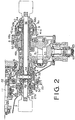
- Figure 2 is a sectional view of a main part of the power transmission system;
- Figure 3 is an exploded perspective view of a part of a central differential.
- Figs. 1 and 2 show a power transmission system for a four-wheel drive motor vehicle to which the present invention is applied. An
engine 1 is laterally mounted on the motor vehicle at a front portion thereof. The power transmission system comprises aclutch 2 housed in aclutch housing 6, atransmission 3, afront differential 4, the latter two housed in atransmission case 7 and a transfer device 5 housed in anextension case 8. Thetransmission 3 has aninput shaft 10, an output shaft 11 parallel with theinput shaft 10, five pairs of change-speed gears 12 to 16 corresponding to first to fifth (overdrive) speed gears, andsynchronizers 17 to 19. Thesynchronizers 17 to 19 are disposed between thegears gears 16, respectively. Areverse drive gear 20 mounted on theinput shaft 10 meshes with agear 21 formed on one side of a sleeve of thesynchronizer 17 through an idler gear (not shown) for reverse drive. - A
drive gear 22 fixedly mounted on the output shaft 11 meshes with afinal gear 23 which is fixed to flanges ofhub members gear 23. Thehub members clutch housing 6 and thetransmission case 7 throughbearings 27a and 27b. Thefront differential 4 is disposed inside thehub members - The front or
secondary differential 4 comprises adifferential case 30 secured to thehub members differential case 30, twodifferential pinions 32 rotatably mounted on the pinion shaft 31 and twobevel side gears pinions 32. Theside gears front axles - In the
extension case 8, acentral differential 9 is provided coaxially with thefront differential 4 and theaxle 36. The central differential comprises adifferential case 40, a pair ofpinions 42, a pair ofpinion shafts 41 rotatably supporting thepinions 42, and a pair ofside gears pinions 42. As shown in Fig. 3, thepinion shafts 41 are integrally formed on a ring 41a which is secured to a tubularfirst drive shaft 45. Namely thepinion shafts 41 are integral with thedrive shaft 45. Thefirst drive shaft 45 is rotatably mounted on asecond drive shaft 46 and connected to thehub member 25. Each of thepinions 42 has a spherical end face 42a (Fig. 3) and slidably supported in an annular and spherical groove 40a formed on the inner wall of thedifferential case 40 so as to revolve in the groove 40a about thesecond drive shaft 46 with the rotation about theshafts 41. - The
side gear 43 is integral with aside gear shaft 47 rotatably mounted on thefirst drive shaft 45 and connected to thedifferential case 40. Theother side gear 44 is securely mounted on thesecond drive shaft 46 which is connected to thedifferential case 30 of thefront differential 4. Thedifferential case 40 is rotatably mounted in atransfer case 8a through abearing 48a and connected to atransfer drive gear 50 which is securely mounted on theside gear shaft 47 and rotatably mounted in theextension case 8 throughbearings 48b. - The
transfer drive gear 50 engages with a drivengear 52 securely mounted on atransfer shaft 51 of the transfer device 5 which is disposed behind theaxle 36 in parallel therewith. Thetransfer shaft 51 is connected to arear drive shaft 55 perpendicular to thetransfer shaft 51 through a pair ofbevel gears rear axles 65 by way of arear drive shaft 55, apropeller shaft 66 and arear differential 67. - In order to restrict the differential operation of the
central differential 9, the system of the present invention is further provided with aviscous coupling 60 in a space on the left side of thefront differential 4. Theviscous coupling 60 comprises ahollow hub 62 secured to thedifferential case 30 as one of the output members of thecentral differential 9 and a cylindrical housing 61 secured to thehub member 24 as an output member of the central differential and rotatably supported in thetransmission case 7 through thebearing 27b. Thehub 62 has a plurality ofinner discs 62a and the housing 61 has a plurality of outer discs 61a which are alternately arranged in the axial direction of theviscous coupling 60. High viscosity fluid is contained in the housing 61. - Describing the operation, the power of the
engine 1 is transmitted to thetransmission 3 through theclutch 2 and theinput shaft 10. By operating thesynchronizers final drive gear 23 through thetransmission 3. The transmitted power is further transmitted to thepinions 42 of thecentral differential 9 through thehub member 25, thefirst drive shaft 45 and thepinion shafts 41. When thepinions 42 revolve about thedrive shaft 46, theside gears pinions 42 are rotated at the torque distribution ratio of 50:50. The torque is transmitted from theside gear 44 to thedifferential case 30 of thefront differential 4 through thesecond drive shaft 46. The torque is further transmitted to the left and right wheels through the pinion shaft 31, thepinions 32 and theside gears right axes side gears 43 to the rear drive wheels through theside gear shaft 47,transfer drive gear 50, drivengear 52,transfer shaft 51,bevel gears rear drive shaft 55, thereby establishing a full time four-wheel drive. - When the vehicle turns around a corner, the difference between speeds of the front and rear wheels is absorbed by the operation of the
central differential 9. Thus the vehicle can smoothly turn the corner. - When one of the front and rear wheels slip and a large speed difference between the
hub 62 and the housing 61 occurs, theviscous coupling 60 engages to restrict the differential operation of thecentral differential 9. Thus, the vehicle can easily get out of the stuck state. - The present invention may be adapted to a rear drive vehicle with a rear engine and also to a vehicle provided with an automatic transmission or a continuously varible transmission.
- From the foregoing, it will be understood that the present invention provides a central differential for a four-wheel drive vehicle where adhesion or vibration of pinions are prevented by the pinion shafts integral with the drive shaft, so that the durability and reliability of the differential are improved. Since the differential between axes is disposed at the same position as the two-wheel drive vehicle, the four-wheel drive vehicle can be easily manufactured by using common parts to the two-wheel drive system.
Claims (3)
- A differential device for a four-wheel drive motor vehicle having an engine transversely mounted on the vehicle, a transversely mounted transmission for transmitting engine power to a first pair of axles (35, 36) adjacent the engine, a front differential (4) for the said first axles, and a final drive gear (22) operatively connected to an output shaft of the transmission, the device comprising a central differential (9) arranged coaxially with one of the first axles (36), and a power transmitting system for transmitting the output of the central differential to a second axle (65) of the vehicle,a respective differential casing (30, 40) for each of the front and central differentials;the central differential comprising a pair of pinion shafts (41) operatively connected to the final drive gear (22); a pinion (42) rotatably mounted on each pinion shaft, and first and second side gears (44, 43) engaged with the pinions;the casing (30) of the front differential being enclosed in a hub member (24, 25) which is operatively connected to the final drive gear (22) and the casing also being operatively connected to the first side gear (44) of the central differential;and the front differential comprising a pair of pinions (32) and a pair of side gears (33, 34) engaged with the pinion (32) and secured to the first axles (35, 36) respectively; andthe pinion shafts (41) being secured to an outer peripheral surface of a first drive member (45) so as to project radially outwardly therefrom, the first drive member (45) being rotatably supported on the first axle (36) and operatively connected to the hub member (24, 25);a transfer drive gear (50) being secured to a side gear shaft (47) of the second side gear (43);a transfer shaft (51) being arranged parallel with the side gear shaft (47) for transmitting the rotation of the transfer drive gear to the second axles (65); and a viscous coupling (60) mounted adjacent to said front differential and having a housing (61) connected to said hub member (24) and a hub (62) connected to said casing (30) so as to limit the differential action of said central differential.
- A differential device according to claim 1, further comprising:a second drive member (46) rotatably mounted on the same axle as the first drive member for connecting the first side gear (44) of the central differential with the casing (30) of the front differential.
- A differential device according to any preceding claim, further characterised by:
an annular groove of spherical cross-section provided on the inner surface of the differential case of the central differential, the wall of the groove being so formed in the case as to slidably guide the pinions.
Applications Claiming Priority (2)
| Application Number | Priority Date | Filing Date | Title |
|---|---|---|---|
| JP59195/89 | 1989-03-10 | ||
| JP1059195A JPH02237822A (en) | 1989-03-10 | 1989-03-10 | Full time four-wheel drive car |
Publications (4)
| Publication Number | Publication Date |
|---|---|
| EP0387053A2 EP0387053A2 (en) | 1990-09-12 |
| EP0387053A3 EP0387053A3 (en) | 1991-02-06 |
| EP0387053B1 EP0387053B1 (en) | 1994-07-13 |
| EP0387053B2 true EP0387053B2 (en) | 1997-05-21 |
Family
ID=13106398
Family Applications (1)
| Application Number | Title | Priority Date | Filing Date |
|---|---|---|---|
| EP90302470A Expired - Lifetime EP0387053B2 (en) | 1989-03-10 | 1990-03-08 | Differential device for a four-wheel drive vehicle |
Country Status (4)
| Country | Link |
|---|---|
| US (1) | US5041068A (en) |
| EP (1) | EP0387053B2 (en) |
| JP (1) | JPH02237822A (en) |
| DE (1) | DE69010528T3 (en) |
Families Citing this family (21)
| Publication number | Priority date | Publication date | Assignee | Title |
|---|---|---|---|---|
| DE59000581D1 (en) * | 1989-07-29 | 1993-01-21 | Volkswagen Ag | TRANSMISSION UNIT FOR A TWO DRIVE AXLE MOTOR VEHICLE. |
| JP2766327B2 (en) * | 1989-07-31 | 1998-06-18 | 栃木富士産業株式会社 | Power transmission device |
| JPH0419233A (en) * | 1990-05-10 | 1992-01-23 | Nissan Motor Co Ltd | Lubricating structure for vehicular power transmission device |
| DE4416678A1 (en) * | 1994-05-11 | 1995-11-16 | Steyr Daimler Puch Ag | Drive unit for motor vehicles with add-on transfer case and central differential |
| SE507150C2 (en) * | 1996-08-28 | 1998-04-06 | Volvo Ab | Transmission for a four-wheel drive vehicle with transverse motor |
| JP4108777B2 (en) * | 1996-12-04 | 2008-06-25 | Gkn ドライブライン トルクテクノロジー株式会社 | Power transmission device |
| US6001043A (en) * | 1997-12-29 | 1999-12-14 | Hyundai Motor Company | Drive mechanism for four wheel drive automobiles |
| CN1064607C (en) * | 1998-03-12 | 2001-04-18 | 周殿玺 | Composite high-passage differential transmission mechanism |
| DE19854379A1 (en) * | 1998-11-25 | 2000-05-31 | Bayerische Motoren Werke Ag | Connection of gearbox output shaft to differential gear of motor vehicle has spur gear or chain drive between output shaft and differential gear, and output shaft is connected to bevel wheel meshing with differential ring gear |
| US6422967B1 (en) * | 1999-11-09 | 2002-07-23 | Dana Corporation | All-wheel-drive motor vehicle transfer case with bevel gear differential |
| EP1136301A3 (en) * | 2000-03-24 | 2005-04-06 | Fuji Jukogyo Kabushiki Kaisha | "Power transmitting system for four-wheel drive vehicle" |
| JP2002144904A (en) * | 2000-11-07 | 2002-05-22 | Fuji Heavy Ind Ltd | Power transmission device for four-wheel drive vehicle |
| JP2002347455A (en) * | 2001-05-23 | 2002-12-04 | Fuji Heavy Ind Ltd | Automatic transmission |
| CN1225374C (en) * | 2001-07-13 | 2005-11-02 | 周殿玺 | Frequently interlocked universal differential driver |
| DE10350870A1 (en) * | 2003-10-31 | 2005-07-21 | Zf Friedrichshafen Ag | Differential gear for a vehicle |
| US6854359B1 (en) * | 2003-11-12 | 2005-02-15 | Xinjiang Shengsheng Co. Ltd. | Transmission mechanism for driving four wheels |
| US8544588B2 (en) * | 2007-11-09 | 2013-10-01 | Ford Global Technologies, Llc | Power takeoff for all-wheel-drive systems |
| EP2271862B1 (en) * | 2008-03-27 | 2015-05-06 | Maxon Motor AG | Dual differential semi-active actuator fit for interaction tasks and fast motion |
| CN102345719B (en) * | 2011-10-24 | 2014-06-11 | 黄炜 | Full-gear mechanical differential lock |
| CN104121349B (en) * | 2014-07-24 | 2016-09-28 | 朱恒 | four-wheel drive transfer case with parking function |
| US10913350B2 (en) * | 2018-09-04 | 2021-02-09 | Ford Global Technologies, Llc | Ranged power take-off unit for transaxle |
Family Cites Families (22)
| Publication number | Priority date | Publication date | Assignee | Title |
|---|---|---|---|---|
| GB2021213A (en) * | 1978-04-28 | 1979-11-28 | Gkn Axles | Differential Gearing, Especially for Vehicles |
| JPS56154328A (en) * | 1980-04-25 | 1981-11-28 | Nissan Motor Co Ltd | Four-wheel-drive vehicle |
| JPS57182527A (en) * | 1981-04-30 | 1982-11-10 | Nissan Motor Co Ltd | 4-wheel-drive vehicle |
| SE440134B (en) * | 1983-01-11 | 1985-07-15 | Volvo Ab | DIFFERENTIALVEXEL |
| JPS59190028A (en) * | 1983-04-13 | 1984-10-27 | Tochigi Fuji Ind Co Ltd | Power transmission device |
| JPS6018656A (en) * | 1983-07-11 | 1985-01-30 | Toyota Motor Corp | Power transmission device for 4-wheel drive car |
| JPS6078832A (en) * | 1983-10-05 | 1985-05-04 | Honda Motor Co Ltd | Driving equipment of all-wheel-drive vehicle |
| FR2561180A1 (en) * | 1984-03-16 | 1985-09-20 | Dangel Automobiles | TRANSMISSION DEVICE FOR A FOUR-WHEELED VEHICLE |
| JPS61122033A (en) * | 1984-11-20 | 1986-06-10 | Daihatsu Motor Co Ltd | Power distributor in four-wheel drive car |
| JPH0343054Y2 (en) * | 1985-02-26 | 1991-09-10 | ||
| JPS61232925A (en) * | 1985-04-09 | 1986-10-17 | Nissan Motor Co Ltd | Four-wheel driving device |
| DE3614847C2 (en) * | 1985-05-15 | 1995-03-09 | Volkswagen Ag | Drive unit for an all-wheel drive motor vehicle |
| US4582160A (en) * | 1985-05-20 | 1986-04-15 | Chrysler Corporation | Constant four wheel drive vehicle transaxle |
| US4601359A (en) * | 1985-06-10 | 1986-07-22 | Chrysler Corporation | Part time on-demand four-wheel drive vehicle transaxle with viscous clutch |
| JPH0647344B2 (en) * | 1985-09-30 | 1994-06-22 | アイシン・エィ・ダブリュ株式会社 | Automatic transmission for four-wheel drive vehicles |
| JPS62143726A (en) * | 1985-12-19 | 1987-06-27 | Fuji Heavy Ind Ltd | 4-wheel drive device |
| DE3600875C1 (en) * | 1986-01-15 | 1987-04-02 | Daimler Benz Ag | Planetary gear transfer case for driving two vehicle axles of a motor vehicle |
| US4779699A (en) * | 1986-04-30 | 1988-10-25 | Mazda Motor Corporation | Four wheel drive vehicle with inter-axle differential having dual planetary gear sets |
| US4817753A (en) * | 1986-09-02 | 1989-04-04 | Mazda Motor Corporation | Interaxle differential restriction device for vehicle four wheel drive systems |
| JPS6397433A (en) * | 1986-10-13 | 1988-04-28 | Mazda Motor Corp | Torque distributing device for four-wheel drive vehicle |
| US4805713A (en) * | 1986-12-12 | 1989-02-21 | Fuji Jukogyo Kabushiki Kaisha | Power transmitting system for a four-wheel drive vehicle |
| JPH01314626A (en) * | 1988-06-13 | 1989-12-19 | Mazda Motor Corp | Four wheel drive car |
-
1989
- 1989-03-10 JP JP1059195A patent/JPH02237822A/en active Pending
-
1990
- 1990-03-02 US US07/488,355 patent/US5041068A/en not_active Expired - Fee Related
- 1990-03-08 EP EP90302470A patent/EP0387053B2/en not_active Expired - Lifetime
- 1990-03-08 DE DE69010528T patent/DE69010528T3/en not_active Expired - Fee Related
Also Published As
| Publication number | Publication date |
|---|---|
| EP0387053A3 (en) | 1991-02-06 |
| EP0387053B1 (en) | 1994-07-13 |
| DE69010528T3 (en) | 1997-09-25 |
| US5041068A (en) | 1991-08-20 |
| DE69010528T2 (en) | 1994-11-10 |
| EP0387053A2 (en) | 1990-09-12 |
| DE69010528D1 (en) | 1994-08-18 |
| JPH02237822A (en) | 1990-09-20 |
Similar Documents
| Publication | Publication Date | Title |
|---|---|---|
| EP0387053B1 (en) | Differential device for a four-wheel drive vehicle | |
| EP0413436B1 (en) | Torque distribution control system for a four-wheel drive motor vehicle | |
| US4441575A (en) | Four-wheel vehicle drive system | |
| USRE32565E (en) | Four-wheel vehicle drive system | |
| US4431079A (en) | Four-wheel vehicle drive system | |
| US5472385A (en) | Differential | |
| US3848691A (en) | Full time four wheel drive | |
| EP0030120A2 (en) | Transmission apparatus for four-wheel drive motor vehicle | |
| US4645029A (en) | Four-wheel vehicle drive system | |
| JPH05306739A (en) | Differential gear | |
| US5484348A (en) | Differential unit | |
| US4671135A (en) | Transmission system for a four-wheel drive vehicle | |
| CN112901752A (en) | Transmission integrated power take-off for commercial vehicle transmission | |
| GB2212232A (en) | Central differential for four wheel drive vehicle | |
| US4967861A (en) | Central differential for a four-wheel drive motor vehicle | |
| EP0411812B1 (en) | Central differential for a four-wheel drive motor vehicle | |
| EP0393285B1 (en) | Coupling device for power transfer | |
| JP3844532B2 (en) | Differential device | |
| JP3641519B2 (en) | Differential device | |
| SE507150C2 (en) | Transmission for a four-wheel drive vehicle with transverse motor | |
| US4907472A (en) | Power transmitting system for a four-wheel drive vehicle | |
| US4915191A (en) | Transfer device for a four-wheel drive vehicle | |
| US4745819A (en) | Compact power transmission device for a four-wheel drive vehicle | |
| US4977796A (en) | Drive system for railroad track vehicle | |
| GB2182735A (en) | Differential gear |
Legal Events
| Date | Code | Title | Description |
|---|---|---|---|
| PUAI | Public reference made under article 153(3) epc to a published international application that has entered the european phase |
Free format text: ORIGINAL CODE: 0009012 |
|
| 17P | Request for examination filed |
Effective date: 19900316 |
|
| AK | Designated contracting states |
Kind code of ref document: A2 Designated state(s): CH DE GB IT LI SE |
|
| PUAL | Search report despatched |
Free format text: ORIGINAL CODE: 0009013 |
|
| AK | Designated contracting states |
Kind code of ref document: A3 Designated state(s): CH DE GB IT LI SE |
|
| 17Q | First examination report despatched |
Effective date: 19920515 |
|
| GRAA | (expected) grant |
Free format text: ORIGINAL CODE: 0009210 |
|
| AK | Designated contracting states |
Kind code of ref document: B1 Designated state(s): CH DE GB IT LI SE |
|
| PG25 | Lapsed in a contracting state [announced via postgrant information from national office to epo] |
Ref country code: IT Free format text: LAPSE BECAUSE OF FAILURE TO SUBMIT A TRANSLATION OF THE DESCRIPTION OR TO PAY THE FEE WITHIN THE PRE;WARNING: LAPSES OF ITALIAN PATENTS WITH EFFECTIVE DATE BEFORE 2007 MAY HAVE OCCURRED AT ANY TIME BEFORE 2007. THE CORRECT EFFECTIVE DATE MAY BE DIFFERENT FROM THE ONE RECORDED.SCRIBED TIME-LIMIT Effective date: 19940713 Ref country code: LI Effective date: 19940713 Ref country code: CH Effective date: 19940713 |
|
| REF | Corresponds to: |
Ref document number: 69010528 Country of ref document: DE Date of ref document: 19940818 |
|
| PG25 | Lapsed in a contracting state [announced via postgrant information from national office to epo] |
Ref country code: SE Effective date: 19941013 |
|
| REG | Reference to a national code |
Ref country code: CH Ref legal event code: PL |
|
| PLBI | Opposition filed |
Free format text: ORIGINAL CODE: 0009260 |
|
| 26 | Opposition filed |
Opponent name: STEYR- DAIMLER- PUCH AKTIENGESELLSCHAFT Effective date: 19950408 |
|
| PLAW | Interlocutory decision in opposition |
Free format text: ORIGINAL CODE: EPIDOS IDOP |
|
| PLAW | Interlocutory decision in opposition |
Free format text: ORIGINAL CODE: EPIDOS IDOP |
|
| PUAH | Patent maintained in amended form |
Free format text: ORIGINAL CODE: 0009272 |
|
| STAA | Information on the status of an ep patent application or granted ep patent |
Free format text: STATUS: PATENT MAINTAINED AS AMENDED |
|
| 27A | Patent maintained in amended form |
Effective date: 19970521 |
|
| AK | Designated contracting states |
Kind code of ref document: B2 Designated state(s): CH DE GB IT LI SE |
|
| REG | Reference to a national code |
Ref country code: CH Ref legal event code: AEN Free format text: AUFRECHTERHALTUNG DES PATENTES IN GEAENDERTER FORM |
|
| REG | Reference to a national code |
Ref country code: GB Ref legal event code: 746 Effective date: 19990121 |
|
| REG | Reference to a national code |
Ref country code: GB Ref legal event code: IF02 |
|
| PGFP | Annual fee paid to national office [announced via postgrant information from national office to epo] |
Ref country code: GB Payment date: 20050302 Year of fee payment: 16 |
|
| PGFP | Annual fee paid to national office [announced via postgrant information from national office to epo] |
Ref country code: DE Payment date: 20050304 Year of fee payment: 16 |
|
| PG25 | Lapsed in a contracting state [announced via postgrant information from national office to epo] |
Ref country code: GB Free format text: LAPSE BECAUSE OF NON-PAYMENT OF DUE FEES Effective date: 20060308 |
|
| PG25 | Lapsed in a contracting state [announced via postgrant information from national office to epo] |
Ref country code: DE Free format text: LAPSE BECAUSE OF NON-PAYMENT OF DUE FEES Effective date: 20061003 |
|
| GBPC | Gb: european patent ceased through non-payment of renewal fee |
Effective date: 20060308 |